
Introduction
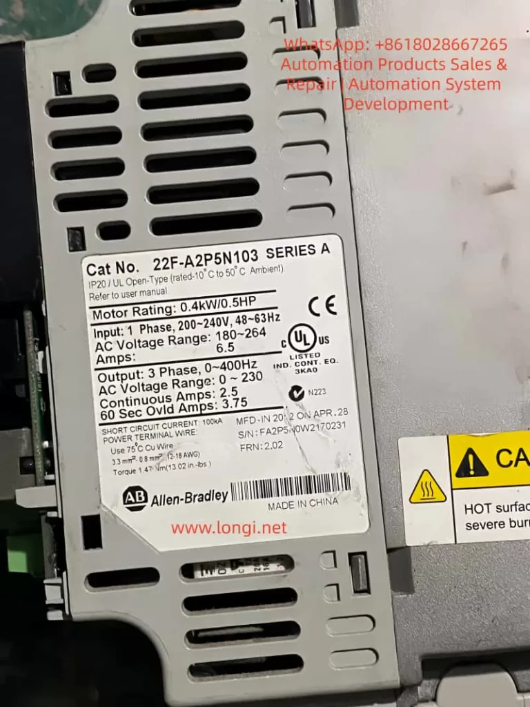
The Allen-Bradley PowerFlex 525 series of inverters are compact AC drives widely used in industrial automation, suitable for motor control ranging from 0.4 kW to 22 kW. This series integrates EtherNet/IP communication, Safe Torque Off (STO) functionality, and a modular design, supporting various control modes such as V/Hz, SVC, and permanent magnet motor control. In practical applications, fault codes are key indicators for diagnosing system issues.
This article focuses on common fault codes F059 (Safety Open) and F063 (Software Overcurrent), providing detailed failure analysis, diagnostic methods, and solutions based on Rockwell Automation official manuals and industry practices. Through systematic troubleshooting, these faults can be effectively resolved to avoid equipment downtime and improve production efficiency.
The PowerFlex 525 fault system is divided into Type 1 (Auto-Reset) and Type 2 (Manual Reset). F059 is Type 1, and F063 is also Type 1. The occurrence of these codes is often related to safety circuits, load conditions, or parameter settings. They are analyzed below.
PowerFlex 525 Inverter Overview
The PowerFlex 525 inverter adopts a modular structure, including a control module, power module, and optional communication adapters. Core specifications include:
- Input Voltage: 200-240V / 380-480V / 525-600V
- Output Frequency: 0-500 Hz
- Overload Capacity: 150% for 60 seconds or 200% for 3 seconds
Built-in safety functions comply with EN 61800-5-2 standards, supporting SIL 2/PL d levels, and reaching SIL 3/PL e when using an external power supply.
The safety input terminals S1, S2, and S+ are the entry points for the STO function, shorted by factory jumpers by default to disable safety mode. Parameter groups include:
- Basic Parameters (P Group)
- Terminal Parameters (t Group)
- Advanced Parameters (A Group)
These are used to configure motor data, current limits, and fault responses. Fault history is recorded in parameters b007-b009 and F604-F610, viewable via Connected Components Workbench (CCW) software or the drive keypad.
Understanding these basics aids in fault diagnosis. F059 and F063 faults often occur during startup, operation, or safety triggers, affecting motor torque output and system stability.

Fault Code F059: Safety Open Failure Analysis
Fault Description
F059 indicates that safety input terminals S1 and S2 are not both enabled, meaning the safety circuit is in an open state. This causes the drive to enter Safe Torque Off mode, where the motor cannot produce torque. The display shows “F059” and the FAULT light illuminates. The fault type is Type 1 and can be configured for automatic reset.
According to the Rockwell manual, the trigger condition is that S1 and S2 inputs do not receive a +24V DC signal, or the signals are inconsistent (discrepancy time exceeds 1 second, firmware version FRN 5.xxx or higher). If the STO function is not used, missing or loose default jumpers will also trigger this fault.
Common Causes
- Safety Circuit Issues: External safety relays, emergency stop buttons, or door switches fail, causing S1/S2 to disconnect. The circuit may have open circuits, short circuits, or interference.
- Jumper Configuration Error: When STO is not used, terminals S1, S2, and S+ must be shorted by factory jumpers. If the jumpers are removed, loose, or damaged, the fault occurs.
- Power Supply Abnormality: +24V DC power supply is unstable, poorly grounded, or the external power supply does not share a common ground with the drive. Current consumption is 6 mA per input; if the power supply is overloaded, signal loss occurs.
- Improper Parameter Settings: Parameter t105 [Safety Open En] defaults to 0 (fault enabled). If not adjusted to 1 (fault disabled), F059 is reported when safety opens.
- Hardware Failure: Safety input monitoring circuit is damaged, or firmware version is incompatible (discrepancy time is 10 ms for early FRN 4.xxx).
- External Interference: Electromagnetic noise, improper cable shielding, or insufficient distance (<0.3 m) between control and power lines cause signal fluctuations.
Diagnostic Steps
- Preliminary Check: View the drive display to confirm code F059. Record fault history (b007 is the most recent fault).
- Voltage Measurement: Use a multimeter to check voltage at S1, S2, and S+ terminals; it should be +24V DC (referenced to digital common terminal 04). Measure continuity and current (>6 mA).
- Jumper Verification: If STO is not used, ensure the yellow jumper firmly connects S1, S2, and S+. Remove the jumper to test STO functionality.
- External Circuit Inspection: Disconnect external safety devices and test relay contacts and E-stops one by one. Use an oscilloscope to observe signal waveforms and check discrepancy time.
- Parameter Reading: View t105, t106 [SafetyFlt RstCfg], and A574 [RdyBit Mode Cfg] via keypad or CCW. Confirm if t105 is set to 1 to disable fault reporting.
- Safety Certification Test: Perform a functional proof test every 24 months, including manually disconnecting one channel to observe F059/F111 (Safety Hardware Fault) response.
- Log Analysis: Check d382 [Torque Current] and b003 [Output Current] to rule out load-related triggers.
Recommended Diagnostic Tools: Fluke 87V Multimeter, Rockwell CCW Software, and Safety Relay Tester.
Fault Code F063: Software Overcurrent Failure Analysis
Fault Description
F063 indicates that the software current limit has been exceeded, meaning the output current exceeds the threshold set by parameters A486/A488 [Shear Pin x Level] and persists longer than A487/A489 [Shear Pin x Time]. The fault type is Type 1 and can auto-reset. The display shows “F063“, indicating that software-level protection is activated to prevent mechanical damage.
This fault differs from hardware overcurrent (F012); it is a parameter-based “Shear Pin” protection that simulates a mechanical shear pin breaking to protect the load.
Common Causes
- Load Abnormality: Sudden increase in motor load, such as mechanical jamming, bearing wear, or conveyor blockage, causing current surge.
- Improper Parameter Configuration: A486/A488 set too low, or A487/A489 time too short. Defaults are 150% of motor rated current but may not match actual load.
- Motor Issues: Motor winding short circuit, insulation degradation, or phase imbalance. Motor data (e.g., P033 [Motor OL Current], P034 [Motor NP FLA]) entered incorrectly.
- Acceleration/Deceleration Settings: Acceleration time P041 is too short, causing starting current peaks to exceed limits. Or regenerative energy is not handled during deceleration.
- Cables and Connections: Motor cable too long (>50 m without shielding), ground fault, or loose terminals causing current instability.
- Environmental Factors: High temperature (>50°C) causes drive thermal protection to indirectly trigger overcurrent, or dust accumulation affects heat dissipation.
- Related Fault Linkage: Unresolved faults like F007 (Motor Overload) or F064 (Drive Overload) can chain-trigger F063.
Diagnostic Steps
- Code Confirmation: Check the display and fault queue (F604-F610 record the last 7 faults).
- Current Monitoring: View real-time b003 [Output Current] and d382 [Torque Current]. Compare with A486/A488 threshold.
- Load Inspection: Disconnect the motor and manually rotate the load to check for jamming. Use a torque wrench to measure mechanical resistance.
- Parameter Verification: Check A484/A485 [Current Limit x] hardware limits (default 200%). Run P040 [Autotune] to auto-tune motor parameters.
- Cable Inspection: Use a megohmmeter to test motor insulation (>1 MΩ) and grounding. Ensure cable shielding coverage >75% and grounding is good.
- Acceleration Test: Gradually extend acceleration time P041 and observe the current curve. Use an oscilloscope to capture peaks.
- Thermal Imaging: Use an infrared thermal imager to check motor and drive temperature to rule out overheating triggers.
- Simulation Test: Run under no load, then gradually add load to simulate actual operating conditions.
Safety Note: Wait 5 minutes after power-off for discharge.
Solutions and Repairs
F059 Fault Solutions
- Circuit Repair: Replace damaged E-stops or relays. Ensure the external +24V power supply shares a common ground with the drive to avoid ground loops.
- Jumper Installation: If STO is not required, reinstall and tighten the jumpers. Reset the fault after testing (press Stop or power cycle).
- Parameter Adjustment: Set t105=1 to disable fault reporting while retaining STO functionality. t106=0 requires power reset.
- Firmware Upgrade: If there is a discrepancy time issue, upgrade to FRN 5.xxx or higher.
- Shielding Optimization: Use Belden 8770 shielded cable and separate control lines from power lines.
- Output Monitoring: Set t069 [Opto Out Sel]=29 “Safe-Off” to indicate STO status externally.
Post-Repair: Run a proof test: manually disconnect S1/S2 to ensure the motor stops torque output immediately.
F063 Fault Solutions
- Load Optimization: Clear mechanical jams, replace worn bearings. Adjust load to below 80% of motor rating.
- Parameter Optimization: Increase A486/A488 to 150-200% of motor FLA, extend A487/A489 to 1-5 seconds. Set A492 [Stall Fault Time] to anti-jam.
- Motor Maintenance: Replace shorted motors, perform insulation tests. Match P031-P036 motor nameplate data.
- Acceleration Adjustment: Extend P041 acceleration time to 10-30 seconds, enable A530 [Boost Select] for low-speed boost.
- Current Limiting: Enable A484/A485, set upper limit to 200%. Add external braking resistors to handle regeneration.
- Environment Improvement: Install fans or air conditioning to ensure ambient temperature <40°C. Clean drive filters.
Post-Repair: Restart the drive and monitor b003 for 1 hour to ensure no recurrence.
Preventive Measures
- Regular Maintenance: Inspect safety circuits, jumpers, and cables quarterly. Perform STO proof tests and motor insulation tests annually.
- Parameter Backup: Use CCW software to back up parameters and compare them regularly to prevent accidental modification.
- Monitoring System: Integrate EtherNet/IP for remote fault logging and current trend analysis. Set alarm thresholds.
- Training & Documentation: Train operators on fault code meanings, provide manuals and flowcharts. Record historical faults to identify patterns.
- Hardware Upgrades: Use shielded cables, external safety relays (e.g., GuardMaster). Avoid long cables (>50 m) without reactors.
- Software Tools: Utilize Studio 5000 Logix Designer for integrated diagnostics and auto-reset Type 1 faults (A541>0).
- Environmental Control: Install in IP20 enclosures, away from vibration and corrosion sources. Monitor input voltage balance (<3%).
These measures can reduce fault incidence by over 50%.
Case Studies
Case 1: F059 in a Packaging Line
A PowerFlex 525 driving a conveyor in a food packaging plant suddenly tripped F059. Diagnosis found oxidized contacts on the E-stop button causing S1 to disconnect.
- Solution: Replaced the button, set t105=1.
- Prevention: Added redundancy to buttons, monthly cleaning.
- Result: Downtime reduced from 4 hours to 30 minutes.
Case 2: F063 in a Pump System
A pump motor in a water treatment plant tripped F063 during operation. Cause: Impeller blockage causing current to exceed A486 150%.
- Diagnosis: Cleaned impeller, adjusted A487 to 3 seconds.
- Prevention: Installed torque sensor linked alarms.
- Result: System ran stably with no recurrence.
Case 3: Mixed Fault Scenario
In an automotive assembly line, multiple 525 drives chained F059/F063. F059 was due to poor grounding of external power supply; F063 was due to short acceleration time.
- Comprehensive Repair: Common grounding for power supply, extended acceleration.
- Prevention: Network monitoring of all drive parameters.
- Result: Efficiency improved by 15%.
These cases are based on industry forums (e.g., PLCtalk) and Rockwell support records, highlighting the importance of diagnosis.
Conclusion
While F059 and F063 faults on PowerFlex 525 inverters are common, they can be resolved quickly through systematic diagnosis and parameter optimization. F059 emphasizes safety circuit integrity, while F063 highlights load-to-current matching. Implementing preventive measures ensures reliable system operation. In the context of Industry 4.0, integrating diagnostic tools like CCW and EtherNet/IP will further improve fault response speed.