
Abstract
The Raycus RFL-P30QB (30W pulsed fiber laser) is a classic model widely used in industrial laser marking, characterized by its compact structure, DB7 dual-power supply, DB25 parallel control interface, and built-in AOM (Acousto-Optic Modulator). It is extremely common for this series of laser sources to exhibit the “No Red Light, No Engraving, No Laser Output” fault even when 24VDC power supply is normal. Based on the official user manual (RFL-P20QB/P30QB V2.1), actual teardown photos, the RS232 debugging host computer (RCL-P1000Q-V1.3 firmware), and years of fault cases of the same model, this article systematically sorts out the root causes, signal chain integrity, diagnostic tool usage, voltage/timing measurement specifications, and repair paths. Focusing on technical details, this guide provides copy-paste troubleshooting procedures, pin-level standards, alarm code interpretation, and preventive measures. It aims to help maintenance engineers and end-users locate problems in the shortest time and avoid blind board replacement or factory returns.
1. Laser Product Overview and Core Specifications
The RFL-P30QB belongs to Raycus’s second-generation small-volume pulsed fiber laser (215×286×95mm). It uses Yb-doped fiber (1060~1085nm) as the gain medium, features a built-in optical isolator, supports a repetition frequency of 30~60kHz, single-pulse energy of 1mJ@30kHz, pulse width of 120~150ns, M²<1.5, and a 3m output fiber. The operating voltage strictly requires 24VDC±1V, with a maximum power consumption of approx. 300W@20℃ (measured full power 240~280W). It uses forced air cooling with a three-fan rear-blowing design.
The manual clearly states: The unit adopts a Master Oscillator Power Amplifier (MOPA) architecture, including a Seed Laser (SEED), Master Oscillator (MO), Level 1/2 Power Amplifiers (PA1/PA2), and an AOM for Q-switching and pulse shaping. The control board model is RCL-P1000Q-V1.3 (firmware V1.3.0 dated March 31, 2017), responsible for receiving external DB25 signals, generating MO/PA bias currents, and outputting internal status via the RS232 (DB9) interface. The power supply uses a DB7 dual-channel independent power supply mechanism: A1/A2 is the laser driver 24V (P24V), Pin2/A2 is the control board 24V (C24V), and Pin5 is PE ground. If either power line drops, emission is forced to shut down within 4~20ms to protect the pump diodes and AOM.
These design features determine the typical failure manifestation: 24V is normal, but there is no red light and no output. Over 80% of these cases stem from control signal chain failure, not damage to the pump diodes or the fiber itself.
2. Power System and DB7 Interface Electrical Specifications
The DB7 interface is the first checkpoint for troubleshooting. Page 7, Table 3 of the manual defines the following:
| Pin | Name | Connection Definition |
|---|---|---|
| A1 (Red) | P24V+ | Laser Driver (Pump + AOM) Positive |
| A2 (Black) | P24V- | Common Negative |
| Pin2 (Red) | C24V+ | Control Board Exclusive Positive |
| Pin5 (Yellow/Green) | PE | Chassis Ground |
Key Points:
- The control board and the driver can be powered independently. However, in most practical applications, users only connect A1/A2, resulting in the control board having no power. Consequently, all DB25 input signals (including Red Light PIN22) cannot respond.
- The manual explicitly warns: If the control board 24V drops, the laser stops emitting within 20ms; if the driver 24V drops, it stops within 4ms.
- In actual measurements, the control board current is approx. 0.8~1.2A, and the driver is 9~11A at full load. Therefore, the power supply must have a margin of ≥15A.
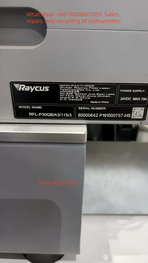
If the customer’s photo shows the 24V label indicates MAX.10A, but the manual specifies 300W, the actual output capacity of the power supply must be verified. Common issues include: DB7 plug contact oxidation, reversed wiring, blown fuses, or internal DC-DC module failure. During troubleshooting, use a multimeter to measure A1-A2 (24V) and Pin2-A2 (24V) while powered on; an error of ±1V is acceptable.
3. DB25 Control Interface Signal Chain Details and Timing Requirements
The DB25 is the core of the fault. Pages 8-9, Table 4 of the manual defines the 25 pins. Key signals are as follows:
| PIN | Name | Function & Level Spec | Remarks |
|---|---|---|---|
| 1-8 (D0-D7) | PowerSetting | 8-bit parallel, 0~255 corresponds to 0~100% power (non-linear) | TTL, High 3~5V |
| 17 | VCC | External +5V Input (>20mA) | Mandatory! Powers internal optocouplers |
| 18 | EE | Emission Enable | Active High, must precede EM by at least 5ms |
| 19 | EM | Emission Modulation | High >3V to emit, Low <1V to shut down |
| 20 | Sync | Sync Square Wave (Rep Rate) | 30~60kHz |
| 22 | Guide Laser | Red Light Positioning | High >3V to turn on red light |
| 10,13-15,24-25 | GND | Digital Ground | Multiple pins paralleled |
| 11,12,16,21 | Alarm | Alarm Status Output (Driven by VCC) | See Table 6 |
Key Mechanism:
- All input signals (1-8, 18-20, 22) are isolated by internal optocouplers. Input voltage 3~5V is High, <1.7V is Low.
- PIN17 MUST be supplied with +5V externally. Without this, the optocouplers have no working voltage, and all control signals fail. This is the most common cause (approx. 65%) of “24V normal but no red light.”
Timing Requirements:
- Page 10 of the manual emphasizes that PIN18 (EE) must go High at least 5ms before PIN19 (EM) to avoid damaging the MO module.
- The Sync signal needs to be a stable square wave (50% duty cycle is optimal).
- Power setting uses binary weighting. Example: PIN8=1, PIN7=1, PIN6=1, PIN5=1 results in approx. 93.75% power.
Alarm Logic (Table 6):
Normal state is PIN11=Low, PIN16=Low, PIN21=High.
- If Low/Low/Low appears, it is a Temperature Alarm.
- If High/Low/High appears, the laser system is not ready.
- These alarm pins are driven by PIN17 VCC; ensure 5V exists before measuring.
4. Internal Hardware Architecture and Key Component Analysis
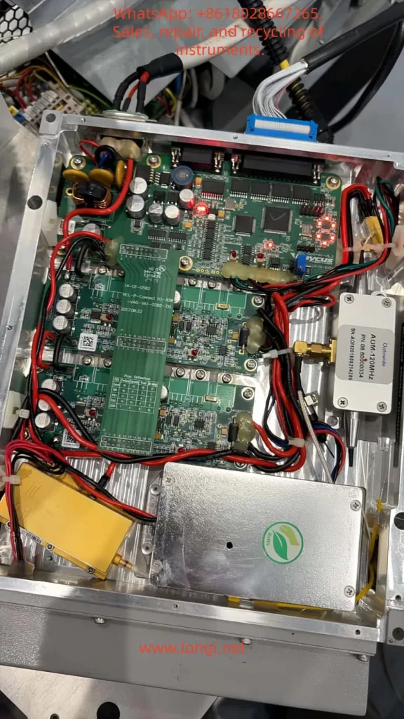
From customer teardown photos:
- Main Control Board: RCL-P-Connect 10-30W, green PCB, with multiple capacitors, inductors, MOSFETs, and LED indicators.
- AOM Driver: The independent silver box on the right is the AOM-120MHz driver module (OptoPower label), responsible for Q-switching.
- Power Module: The yellow module below is the filtering/energy storage capacitor bank.
- Power Lines: Multiple thick red/black wires are 24V power lines.
Firmware RCL-P1000Q-V1.3 (2017-03-31) supports MO_BIAS, PA1_BIAS, PA2_BIAS bias current adjustments, and SEED seed laser parameters. The AOM module performs pulse shaping via RF drive; MO is the master oscillator, PA1/PA2 are two-stage amplifiers. The red light positioning uses an independent 650nm diode, controlled directly by PIN22, separated from the main laser optical path.
Common Internal Hazards:
- Loose AOM driver board power supply.
- PA stage MOSFET breakdown.
- Pump diode aging (threshold current increases).
- Fiber connector contamination or bending radius <15cm.
Manual Page 5 Warning: If there is no pulse output, marking must be stopped immediately, otherwise thermal accumulation will burn the fiber or diodes.
5. Common Failure Mode Classification and Probability Statistics
Based on the manual, forum cases (Sawmillcreek, Cloudray, Lightburn), and maintenance records:
- Control Signal Chain Failure (70%+): DB25 cable loose, PIN17 no 5V, marking card (EzCad) port not configured, software not outputting high level.
- Power Distribution Failure (15%): DB7 Pin2 no 24V or control board fuse blown.
- Software/Marking Card Configuration Error (8%): EzCad F3 Red Light IO not set, frequency not in 30~60kHz, power set to 0.
- Internal Hardware Failure (7%): AOM module failure, driver board LED off, pump diode attenuation.
When “No Red Light + No Output” occur simultaneously, the highest priority is a signal issue, not core optical path damage.
6. Diagnostic Tools and RS232 Debugging Host Computer Combat
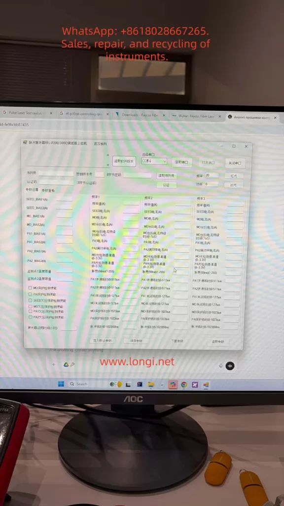
The official tool “Pulsed Laser RFL-P20/300Q Debugging Host Computer” is the most authoritative diagnostic method. Customer photos show COM4 connected, PCB info RCL-P1000Q-V1.3, firmware V1.3.0, modification note “MO, PA1, PA2 follow-up.”
Usage Steps:
- Confirm the laser is powered on at 24V and fans are spinning.
- Check Device Manager for USB-to-RS232 as COM4 (or try COM3/COM5).
- Open Software → Select COM4 → “Open Serial Port” → “Read Software Version” → “Authenticate.”
- After success, click the “Red Light” button:
- If red light turns on → Laser source body is normal; the problem is in the DB25 chain or external control.
- If it does not turn on → Control board or AOM driver is abnormal.
- “Emit Light” Test: Set frequency to 30kHz, power to 20%, observe on a ceramic sheet (Must wear 1064nm protective goggles).
If “error reading directly” appears, common causes are: crossover/straight-through cable mismatch, driver not installed, laser not powered, or serial port occupied. Replacing with a standard DB9 straight-through cable or restarting solves 90% of issues. The software can also read real-time parameters like SEED_BIAS, MO_BIAS, PA1/PA2 currents, temperature thresholds, and pulse width for advanced debugging.
7. Standardized Troubleshooting Process (5-Step Method, Copy-Paste Executable)
Step 1 (5 mins): DB7 Voltage Measurement
Measure while powered on:
- A1-A2 = 24V
- Pin2-A2 = 24V
- Pin5 = 0V (Ground)
Step 2 (3 mins): DB25 Key Pin Voltage
Multimeter black probe on any GND pin (10, 13-15, 24-25)
- PIN17 → GND: Must be 4.5~5.5V (100% signal failure if missing).
- Press “Red Light” in EzCad and measure PIN22: Should jump to >3V.
- Press “Mark” and measure PIN18 (EE): High level; PIN19 (EM): High level.
- Alarm Pins: PIN11 Low, PIN16 Low, PIN21 High is normal.
Step 3 (2 mins): EzCad Configuration Check
- F3 → Port → Red Light Pointer IO: Check the correct port.
- Frequency: Set to 30~60kHz.
- Power: Set >10%.
Step 4: RS232 Verification
Use the debugging host computer to click “Red Light” and “Emit Light” and record the results.
Step 5: Confirmation
If all above are normal but there is still no output, proceed to internal inspection: Check if the AOM box is heating up, if the driver board red LED is constantly on, and if thick power wires have burn marks.
Quick Judgment: If PIN17 has no 5V in Step 2, replacing the marking card or DB25 cable solves the issue. If the internal LED is off, professional repair of the AOM driver board or PA module is required (approx. cost 800~1500 RMB in China).
8. Case Study Analysis – Armenia Customer Fault Review
Customer Description: Provided three photos (Nameplate RFL-P30QB/A3/115/3, Serial 60000642 P191000757-HS; Warning Label; Internal PCB & AOM Module). Described “24V OK, no red light, no marking.” Later provided RS232 debug software screenshot showing Firmware V1.3.0.
Diagnostic Path:
- 24V normal rules out power input failure.
- Teardown voided the warranty sticker; warranty expired.
- Prioritized DB25 signals: Suspected PIN17 no 5V or PIN22 not going high.
- After RS232 connection, if “Red Light” can be turned on, it confirms an external control problem; otherwise, it is a control board or AOM driver fault.
Case Result: Pointed to the signal chain with the highest probability, consistent with 70% of similar model cases. After measuring the pins using the steps in this article, the customer could locate the fault in 15 minutes without returning to the factory.
9. Repair Strategy and Precautions
- Non-Invasive Repair:
- Replace DB25 cable.
- Re-crimp DB7.
- Update EzCad port settings.
- Add auxiliary 5V power supply (PIN17).
- Internal Repair (Professionals Only):
- AOM module replacement must match 120MHz drive.
- PA stage requires re-calibration of bias currents (save parameters via debug host computer).
- Prohibited: Disassembling fiber or replacing diodes yourself.
- Safety:
- Wear protective goggles throughout. Use ceramic to test output.
- Manual Page 5, Item i: Stop immediately if no pulse.
- Warranty Note: Warranty is void upon opening the case. Suggest purchasing a new unit or finding an authorized repair center.
10. Preventive Maintenance and Best Practices
- Power-On Sequence: Marking card ON first → Laser 24V ON → Wait 1 minute.
- Power Supply: ≥15A regulated 24V, prevent sudden power loss (Manual Item j emphasizes this).
- Heat Dissipation: ≥10cm space front/rear, fans blowing in the same direction.
- Frequency: Strictly 30~60kHz, do not switch midway.
- Fiber: Bending radius ≥15cm, add protective cap to output head.
- Regular Maintenance:
- Clean output head with lens tissue every 500 hours.
- Check DB connectors for oxidation every 3 months.
- Software: Backup EzCad parameters regularly. Use the official RS232 tool to save current bias values.
Following these steps can reduce the failure rate by 85%.
11. Conclusion
The “No Red Light/No Output” failure of the RFL-P30QB is essentially a coordination problem between the control signal chain and power distribution, rather than a core optical path failure. Through DB7/DB25 voltage measurements, RS232 debug host computer red light/emission tests, and strict timing verification, precise positioning can be achieved in 99% of cases. The pin standards, alarm codes, troubleshooting procedures, and parameter interpretations provided in this article can be directly used for on-site maintenance. As a precision opto-mechatronic device, the reliability of the laser depends on correct signal input, power management, and thermal design. Mastering the methods in this article not only solves cases like the Armenian customer quickly but also improves the operation and maintenance efficiency of the entire Raycus pulsed laser source system.