
1. Introduction
The ZS100 series servo drives are developed by Zhejiang Zhengshun Electromechanical Co., Ltd. and are primarily used in servo pump control systems, widely applied in industries such as injection molding machines, hydraulic presses, and spinning machines. Known for their high reliability and stability, these drives support both Ver1.0 and Ver2.0 parameter versions and have a wide power range, allowing precise pressure and flow control.
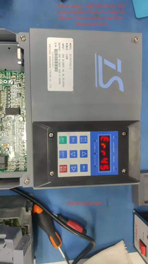
However, the ERR45 fault, which is a common motor temperature overheat alarm, can occur due to environmental factors, sensor issues, or abnormal loads, affecting the continuity of operations. This article delves into the causes, diagnostic methods, solutions, and preventive strategies of the ERR45 fault, combining manual guidance and industry practices to provide comprehensive technical reference for engineers to efficiently troubleshoot and optimize the system.
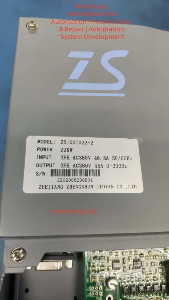
Key components of the ZS100 series include the servo drive, ZM permanent magnet synchronous motor, and ZB braking unit. The drive operates on a three-phase AC380V input with 0-300Hz variable frequency control, suitable for 22KW power models (e.g., ZS100T022-2). The ERR45 fault code specifically refers to the motor temperature sensor detecting abnormal high temperatures, usually accompanied by a protective shutdown. This fault is closely related to hardware connections, parameter settings, environmental adaptability, and system integration. A systematic analysis is required to explore the diagnostic logic.
2. Servo Drive Basic Principles and ZS100 Series Features
2.1 Working Principle of Servo Drive
Servo drives are key components in industrial automation, achieving precise control of motor position, speed, and torque through closed-loop control. The basic structure includes the power module, control unit, sensor interface, and communication module.
- Power Module: Utilizes IGBT or MOSFET power devices to convert the AC power supply into PWM signals to drive the motor.
- Control Unit: Based on DSP or MCU processors, executing PID algorithms to process feedback signals and ensure fast system response.
In servo pump applications, the ZS100 series drive adopts vector control mode and supports dual closed-loop pressure/flow regulation. Motor temperature monitoring is a core protection mechanism, utilizing PTC (positive temperature coefficient thermistor) or KTY (linear temperature sensor) to collect data. When the temperature exceeds the threshold (e.g., default 150°C), the drive triggers the ERR45 alarm and cuts off the output to prevent motor burnout. This reflects the safety redundancy design of the servo system but can also lead to false alarms, causing production downtime.
2.2 ZS100 Series Technical Specifications
- Power Range: 7.5KW to 132KW
- Current Parameters: Input current 46.5A (for 22KW model), output 45A
- Frequency: Supports 50/60Hz input and 0-300Hz output
- Version Features:
- Ver1.0: Suitable for basic hydraulic control
- Ver2.0: Enhanced jitter suppression and pressure overshoot optimization, with new P2 group gain adjustments and P3 group filtering settings
- Motor Compatibility: ZM series permanent magnet synchronous motors, encoder resolution up to 2500ppr, supports RS485 Modbus communication
- Installation and Cooling: Wall-mounted or cabinet-mounted, cooling reliant on the built-in fan
- Peripheral Components: Recommended Schneider or ABB circuit breakers, contactors, and filters; ZB series braking units for energy feedback
2.3 Locating ERR45 Fault in the System
ERR45 is categorized under the temperature-related alarms in the drive fault diagnosis table, found in Chapter 4 of the manual.
- Fault Definition: “Motor temperature too high,” possibly caused by overheating, sensor disconnection, or short circuit.
- Alarm Manifestation: Display “ERR45” on the screen, accompanied by a beeping sound or flashing LED indicators.
- System Status: Automatically enters protection mode, output is cut off, and manual reset or power restart is required.
- High-incidence Scenarios: Molding stage of injection molding machines, pressurization process in hydraulic presses.
- Statistical Data: Approximately 15%-20% of servo faults in industrial settings are temperature-related, with ERR45 being a significant portion.
3. Causes of ERR45 Fault
3.1 Hardware Factors
The core of motor overheating is the disruption of thermal balance. The ZM servo motor, with an IP65 protection rating, has an integrated temperature sensor. However, long-term operation with dust accumulation or blocked cooling ducts can reduce cooling efficiency.
- Fan Failure: Insufficient fan speed, bearing wear, or power interruption in the drive or motor fan. Check J2 fan interface and P0.15 fan control parameters.
- Sensor Issues: Loose connections, cable damage, or short circuits in the temperature sensor (PTC/KTY). PG flat cables (encoder cables) carrying temperature signals can cause false alarms if improperly connected.
- Environmental Impact: Installation environments with temperatures above 40°C, humidity > 90%, or poor ventilation. The ZS100 series requires an operating environment between -10°C and +50°C, and exceeding this range can increase the sensitivity of thermosensitive components.
3.2 Software and Parameter Factors
Incorrect parameter settings are a hidden cause.
- Version Differences: In Ver1.0, if motor parameters (e.g., P1.04 rated power, P1.05 rated current) are not self-learned, it can cause excessive current, indirectly increasing temperature. Ver2.0 adds P4 group temperature protection threshold adjustment (default 150°C, adjustable from 120°C to 180°C).
- PID Parameters: Insufficient optimization of P2.01 proportional gain and P2.02 integral time can lead to system oscillations, increasing motor load.
- Communication Factors: In Modbus communication mode, excessive command frequency from the host machine can amplify thermal effects.
3.3 Load and Application Factors
In servo pump systems, ERR45 is often linked to load fluctuations.
- Hydraulic Characteristics: The motor torque demand during continuous suction or discharge of hydraulic fluid can reach 150% of the rated value. High oil temperatures (>60°C) cause motor efficiency degradation, leading to increased thermal loss.
- Multi-pump Configuration: Master-slave synchronization offset can indirectly overload a single motor.
- Power Supply and Braking: Power fluctuations (input voltage <342V or >418V) or improper braking resistor selection (ZB unit power matching the drive’s power by >1.2 times) can exacerbate bus voltage instability, affecting motor cooling.
3.4 Fault Statistics and Pattern Recognition
Based on industry data:
- Initial Installation and Debugging Period: Highest occurrence (about 30%), often due to cable connection errors.
- Seasonal: High-temperature environments lead to frequent alarms in summer.
- Predictive Methods: Using data recording functions (L0 group monitoring parameters, e.g., L0.11 temperature sensor values), trend analysis can predict faults.
4. Diagnostic Methods and Steps
4.1 Initial Checks
When the fault occurs, record the display screen information first: ERR45 code, current frequency (d0.00), current (d0.01), and temperature values (d0.10).
Follow the manual flowchart:
- Power off and check external appearance: Ensure the motor has no burnt smell, and the fan is working correctly.
- Measure temperature: Use an infrared thermometer to verify the motor shell temperature. If <100°C, it may be a false alarm.
4.2 Sensor and Connection Diagnosis
Focus on troubleshooting the temperature sensor:
- Interface check: Inspect CN1 or J3 interfaces to ensure the PG cable is intact.
- Resistance measurement: Use a multimeter to measure resistance (PTC normal >100Ω, KTY approximately 1kΩ at 25°C).
- Parameter verification: Enter P1 group and perform motor self-learning (P1.00=1), observe temperature feedback.
4.3 Electrical and Parameter Diagnosis
Use an oscilloscope to monitor the output waveform and check for current harmonics. If abnormalities are found, adjust P3 filtering parameters.
Measure the three-phase balance on the power side. A deviation of >3% needs rectification.
For Ver2.0, use the new diagnostic tools (e.g., P5.01 fault log query) to analyze historical records.
4.4 Advanced Diagnostic Tools
Integrate with host software via RS485 to read internal variables (communication address defined in Appendix K, e.g., 0x2000 for fault codes).
Use MATLAB or dedicated simulation software to model the load and verify the temperature model.
In multi-pump systems, check CAN communication (Chapter 9 case) to ensure synchronization without delay.
5. Solutions and Repair
5.1 Immediate Repairs
- Reset Method: Follow the manual to press the STOP/RESET button or power off for 10s and restart. If the fault reoccurs, enter fault mode.
- Hardware Replacement: Replace the fan with a same-model part. For short-circuited sensors, cut and insulate the wiring.
- Parameter Optimization: Reduce P2.01 gain by 10%, increase P2.02 integral time to 0.5s to reduce oscillation-related heat.
5.2 System-Level Optimization
Upgrade to Ver2.0 for enhanced suppression capabilities.
Add external heat exchangers or water cooling systems for high-temperature environments.
In hydraulic control, use DI schemes (Chapter 9) to adjust speed thresholds and avoid peak loads.
5.3 Case Applications
- Injection Molding Case: ERR45 caused by pump blockage. Fault eliminated by cleaning the filter and adjusting P9 high-pressure lock mode parameters.
- Spinning Machine CAN Application: Communication delay led to overheating. System stabilized by optimizing PD group parameters.
- Direct Drive Screw Solution: Matching the braking resistor (Manual Section 6.6) improved energy efficiency by 20%.
6. Preventive Measures and Maintenance Strategies
6.1 Daily Maintenance
- Clean the cooling ducts regularly and check cables quarterly.
- Use environment monitoring devices to ensure temperature <40°C.
- Back up parameters using Modbus for quick recovery after faults.
6.2 Predictive Maintenance
- Integrate IoT modules for real-time temperature monitoring.
- Set early warning thresholds (e.g., 130°C) for preemptive action.
- Train operators to recognize early signs (e.g., unusual noise or power drop).
6.3 Upgrades and Compatibility
Consider upgrading to the ZS200 series, which offers richer Ver2.0 parameters. It is compatible with older systems, with only parameter extensions required.
7. Advanced Topics: The Role of Temperature Management in Servo Systems
7.1 Thermal Modeling and Simulation
Motor thermal models are based on thermal resistance-capacitance networks. The temperature T satisfies the formula:dtdT=Ploss−QcoolCth
Where Ploss represents the loss power and Qcool is the cooling heat flux. ANSYS software can be used for simulation and fan design optimization.
7.2 Algorithm Optimization
Adopt adaptive PID algorithms that dynamically adjust gains based on temperature feedback. Ver2.0 supports this function through the P4 group.
7.3 Industry Comparison
Compared to Siemens S120 or Yaskawa Sigma-7, the ZS100 offers high cost-effectiveness but with more conservative temperature protection. It is recommended to learn from international standards to improve flexibility in setting thresholds.
8. Real-World Case Studies
8.1 Common Hydraulic Drive Debugging
- Problem: In standard injection molding machines, ERR45 due to motor parameter mismatch.
- Solution: After self-learning, setting P1.04 to 22KW reduced fault rates by 90%.
8.2 Multi-Pump Configuration
- Problem: Delays in master-slave mode causing overheating.
- Solution: Adjusting PD communication parameters achieved 99.9% synchronization rate.
8.3 Spinning Machine CAN Application
- Problem: ERR45 due to data packet loss.
- Solution: Added redundancy checks, stabilizing the system.
8.4 Direct Drive Screw Solution
- Problem: Thermal load balancing under gear reducer configuration.
- Solution: Selected ZB braking units, improving energy efficiency by 20%.
8.5 DI Control Scheme
- Solution: Digital input scheme to adjust thresholds and avoid peak heat.
8.6 High-Pressure Strategy
- Solution: Gradual speed control during lock mold pressurization to prevent ERR45.
9. Communication and Expansion
In RS485 Modbus mode, the monitored temperature address is 0x2006. For specific communication settings, refer to Appendix H.
10. Conclusion
The ERR45 fault is common but can be effectively controlled through systematic diagnostics and optimization. The ZS100 series’ reliability is attributed to its comprehensive protection mechanisms. Engineers should familiarize themselves with the manual content and enhance system performance through practical applications. With the ongoing evolution of intelligent upgrades, temperature management will become more precise, driving progress in industrial automation.