
Introduction:
In the field of industrial automation, variable frequency drives (VFDs) are critical components used for controlling motor speed, ensuring efficient and reliable operations. However, due to their complex environment and diverse components, VFDs often encounter failures that impact the continuity and stability of production processes. One of the key components prone to failure in VFDs is the DC bus pre-charge resistor. Specifically, in the Fuji FRENIC-E1S series inverter, this component is highly susceptible to damage from excessive heat, overloads, and other operating stresses.
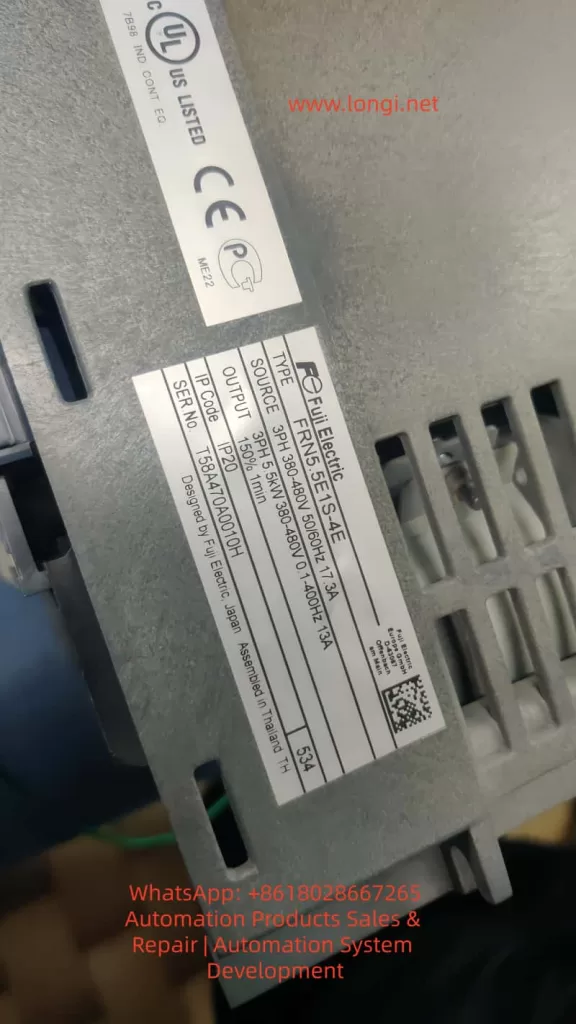
This article focuses on the failure of the DC bus pre-charge resistor in Fuji FRENIC-E1S inverters, analyzing its role, common causes of failure, diagnostic methods, and offering practical repair solutions. The goal is to help technicians and engineers better understand this critical component and equip them with effective methods for maintaining and restoring inverter functionality.
1. The Role of the DC Bus Pre-Charge Resistor in Variable Frequency Drives
1.1 The DC Bus Capacitor Charging Process
Inverters, including the Fuji FRENIC-E1S, require DC bus capacitors to be charged upon startup. These capacitors are essential for storing energy in the DC bus and enabling smooth operation of the inverter. However, directly charging these capacitors can result in large inrush currents, which can damage both the power supply and other components of the inverter. This is where the pre-charge resistor comes into play.
1.2 Function and Design of the Pre-Charge Resistor
The primary function of the pre-charge resistor is to limit inrush current when the inverter is powered on. It allows the DC bus capacitors to charge slowly by dissipating the charging current over a longer period. Once the charging process is complete, the resistor is bypassed by a relay or thyristor (SCR), thus minimizing power loss and optimizing efficiency.
In the Fuji FRENIC-E1S, the pre-charge resistor helps ensure that the DC bus voltage increases gradually and stabilizes at the designed value. This process prevents sudden large currents, which could damage sensitive components of the inverter.
2. Common Causes of DC Bus Pre-Charge Resistor Failure
2.1 Causes of Pre-Charge Resistor Failure
The failure of the pre-charge resistor is typically caused by the following factors:
- Overload of Current: When the inverter experiences frequent starts or the bus capacitors have a larger capacity, the pre-charge resistor is subjected to prolonged high currents, which may lead to overheating and failure.
- Faulty Relay or Thyristor: If the relay or thyristor used to bypass the pre-charge resistor fails, the resistor will be subjected to continuous high power, eventually causing it to overheat and burn out.
- Power Fluctuations or Missing Phases: Inverters are sensitive to fluctuations in the input power supply. If the power supply is unstable or the inverter operates with missing phases, the DC bus capacitors may not charge properly, placing excessive strain on the pre-charge resistor.
- Aging of Bus Capacitors: As the bus capacitors age, their charging characteristics change, leading to longer pre-charge times. This increased load on the pre-charge resistor can eventually cause it to burn out.
- High Ambient Temperature: In high-temperature environments, the resistor’s heat dissipation capacity may be compromised, leading to overheating and failure.
2.2 Symptoms of Pre-Charge Resistor Failure
When the pre-charge resistor fails, the inverter often exhibits the following symptoms:
- Inverter Fails to Start: Since the pre-charge resistor is responsible for the initial charging of the DC bus capacitors, a failed resistor prevents proper charging, and the inverter fails to start.
- Alarms or Fault Codes: In some inverters, the failure of the pre-charge resistor triggers alarms or fault codes such as overcurrent or startup failure.
- Power Instability: A burned pre-charge resistor can cause instability in the power supply, leading to frequent shutdowns or restarts of the inverter.
3. Diagnosing and Troubleshooting DC Bus Pre-Charge Resistor Failure
3.1 Fault Code Diagnosis
Many inverters come equipped with a fault diagnostic system. When a failure occurs, the inverter will display a fault code indicating the issue. For example, in the Fuji FRENIC-E1S, a burned pre-charge resistor may trigger fault codes such as “Overcurrent” or “Startup Failure.” These codes can serve as initial clues for identifying the problem.
3.2 Visual Inspection of the Resistor
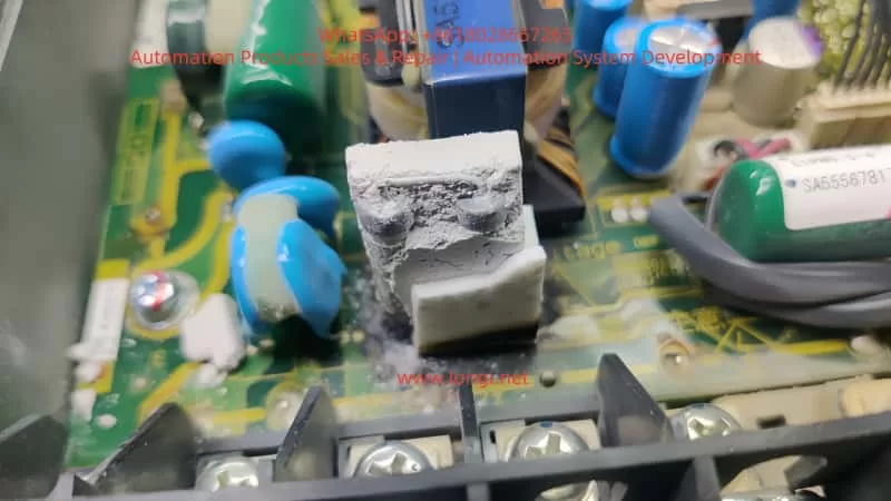
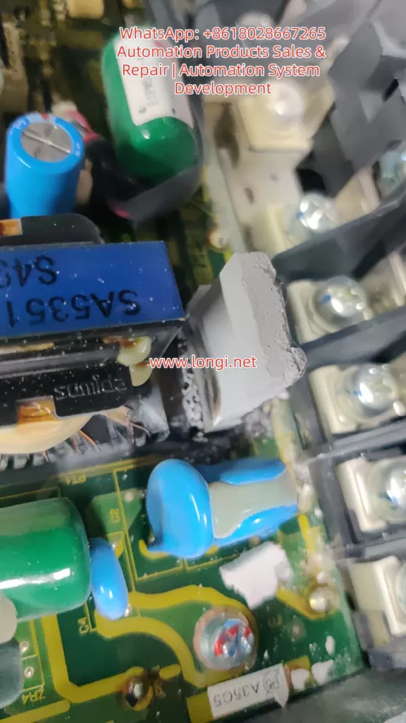
A visual inspection can provide immediate insights into whether the pre-charge resistor has failed. Common signs of failure include:
- Burnt marks or white powder on the surface of the resistor.
- Cracked or damaged resistor leads.
- Overheating signs such as melted or charred components around the resistor.
3.3 Measuring Resistor Value
A multimeter can be used to measure the resistance of the pre-charge resistor. If the measured resistance deviates significantly from the nominal value (usually 22Ω to 27Ω), or if the resistor is open or shorted, it confirms the resistor is damaged.
4. Replacing and Repairing the DC Bus Pre-Charge Resistor
4.1 Preparation for Replacement
Before replacing the pre-charge resistor, ensure that the inverter is powered off and completely cool. Open the inverter enclosure, disconnect the power supply, and prepare the necessary tools and replacement resistor.
4.2 Removing and Replacing the Resistor
- Remove the Old Resistor: Use appropriate tools to remove the damaged resistor. Resistors are typically soldered onto the PCB, so use a desoldering pump or hot air rework station to carefully remove it.
- Clean the PCB: After removing the old resistor, clean the PCB with electronic cleaner to remove any residue or burnt material, ensuring that the new resistor can be securely mounted.
- Install the New Resistor: Choose a replacement resistor with the same specifications (typically 22Ω – 27Ω and 30W – 50W), and solder it into place on the PCB. Ensure that the solder joints are secure and free of cold solder connections.
4.3 Checking the Relay and Capacitors:
After replacing the resistor, check the pre-charge relay and the DC bus capacitors:
- Relay Test: Verify that the pre-charge relay operates correctly, switching from charging to bypass mode once the capacitors are sufficiently charged.
- Capacitor Check: Measure the bus capacitor voltage and ESR (Equivalent Series Resistance) to ensure that the capacitors are not aging or damaged.
4.4 Testing the Inverter:
After replacing the resistor, reconnect the power supply and power on the inverter. Observe if it starts up normally and check for any fault codes. If the inverter operates without issues, the problem has been resolved.
5. Preventive Measures and Maintenance Recommendations
5.1 Regular Inspection and Maintenance
To prevent pre-charge resistor failure, regular maintenance of the inverter is essential. This includes periodic checks on the pre-charge resistor, relay, and bus capacitors. Cleaning the PCB, inspecting the resistor condition, and monitoring ambient temperature can help extend the life of the components.
5.2 Environmental Control
Inverters should be installed in environments with suitable temperature and humidity levels. Avoid installing them in high-temperature or humid environments, as this can impact the resistor’s heat dissipation capability and lead to overheating.
5.3 Using High-Quality Components
When selecting components for the inverter, use high-quality resistors and other electrical components. This ensures that the pre-charge resistor is capable of handling the required power and prevents premature failure.
6. Conclusion
The DC bus pre-charge resistor is a small but vital component in a variable frequency drive. Its failure can lead to significant issues such as startup failure and power instability. By understanding the role of the pre-charge resistor, diagnosing the causes of its failure, and following proper repair procedures, technicians can restore the inverter to full functionality. Regular maintenance and preventive measures are essential for ensuring the longevity and reliability of VFDs, minimizing downtime, and optimizing production processes.
For VFD operators and service providers, understanding the working principles and failure modes of key components like the pre-charge resistor is crucial for keeping the system running smoothly and preventing costly downtime.