
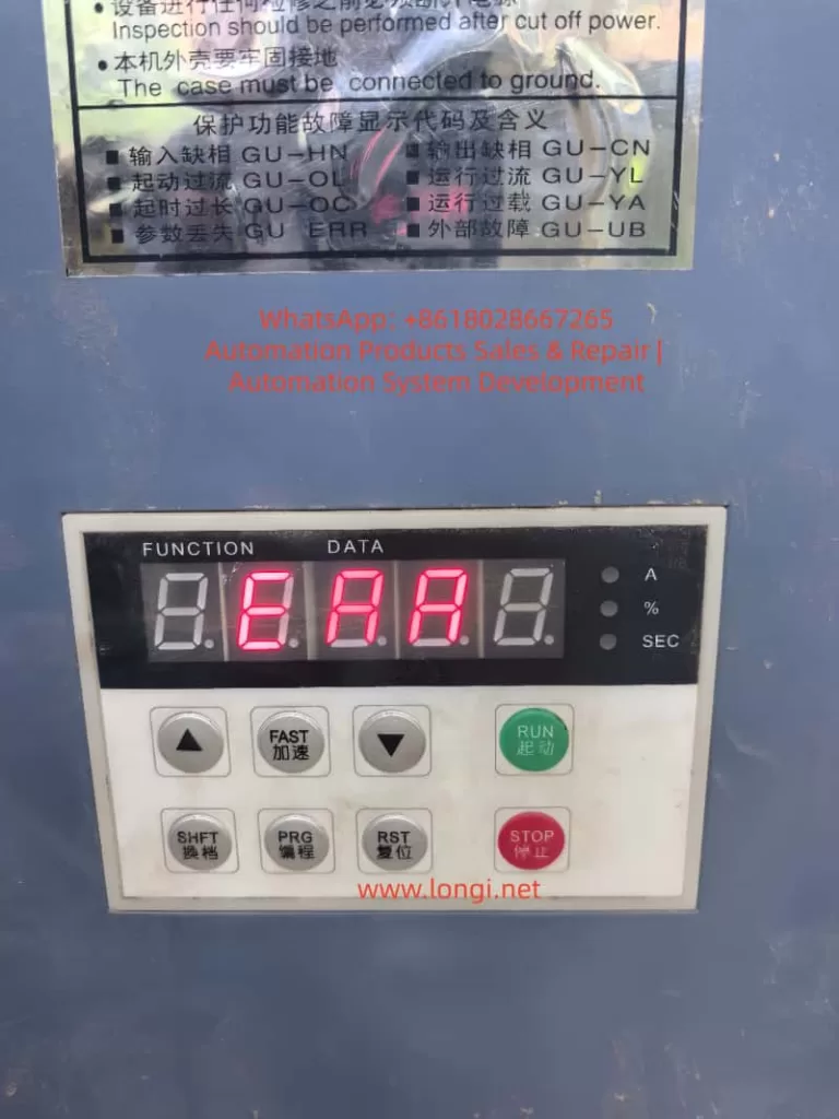
When a DELIXI CDJ1 soft starter powers on, the display lights up, but shows E.AA, and none of the keypad buttons respond, this should not be treated as a normal motor overload, overcurrent, phase loss, or emergency stop fault.
For CDJ1 series soft starters, ordinary protection faults are usually displayed as defined fault codes such as Err-0, Err-1, Err-2, Err-3, Err-4, Err-5, Err-6, Err-7, Err-8, or d.Err. However, E.AA is not listed in the standard fault table. More importantly, the keypad has no response. This means the problem is probably not a normal external running fault, but an internal control system fault.
In this situation, the most likely causes are:
- Main control board failure
- Keypad communication failure
- Low-voltage control power supply fault
- EEPROM parameter storage fault
- MCU reset or oscillator failure
- Damaged keypad board or ribbon cable
Among these possibilities, the main control board should be considered the primary suspect, especially if reseating the keypad cable and checking the external control terminals does not change the fault.
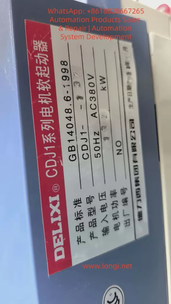
1. Basic Structure of the CDJ1 Soft Starter
The CDJ1 soft starter is used to start three-phase squirrel-cage induction motors smoothly. Its main function is to control the firing angle of three-phase thyristors, allowing the motor voltage to rise gradually during startup. This reduces starting current, mechanical shock, and stress on the motor and driven machine.
A typical CDJ1 soft starter contains several main sections.
The first section is the power circuit. This includes the three-phase input terminals, three-phase output terminals, anti-parallel thyristor modules, current detection circuits, heat sink, temperature detection, and bypass contactor control circuit.
The second section is the low-voltage control power supply. This circuit generates voltages such as +5V, +12V, or +15V for the control board, keypad board, detection circuits, relay circuits, optocouplers, and communication circuits.
The third section is the main control board. This board normally contains the MCU, EEPROM or parameter memory, reset circuit, crystal oscillator circuit, current and voltage sampling circuits, phase loss detection, thyristor trigger output, relay drive circuit, keypad interface, and communication interface.
The fourth section is the keypad display board. This board displays operating status and fault codes, scans keypad buttons, and communicates with the main control board through a ribbon cable or connector.
Under normal conditions, after power-on, the main control board performs self-checking, reads parameters from memory, checks the three-phase input, checks control terminals, verifies emergency stop input, monitors current detection signals, and then enters standby or ready mode.
If a standard fault is detected, the soft starter displays a defined fault code. If the system does not even enter the normal display and operation logic, then the fault may be inside the control system itself.
2. Why E.AA Is Not Like a Normal External Fault
For normal CDJ1 protection faults, the display should follow the fault code table. For example:
Err-0 usually indicates phase loss.
Err-1 usually indicates overheating.
Err-2 usually indicates overload.
Err-3 usually indicates light load.
Err-4 usually indicates three-phase current imbalance.
Err-5 usually indicates emergency stop.
Err-6 usually indicates overcurrent.
Err-7 usually indicates control board fault.
Err-8 usually indicates excessive starting time.
d.Err usually indicates parameter error.
The displayed code E.AA does not belong to this normal fault code format. Therefore, it should not be directly treated as phase loss, overload, overcurrent, or emergency stop.
The more important symptom is that the keypad does not respond. In a normal protection fault, the control board is still running. It detects the fault and displays the corresponding code. In that condition, the keypad should usually still work. The user should normally be able to press STOP, RESET, PRG, SHIFT, or other keys to check parameters or clear the fault.
If all buttons have no response, it means the control logic may not be running properly. The keypad board may not be communicating with the main board, or the main control board may be stuck during initialization.
This is why E.AA plus no keypad response is much more serious than an ordinary protection alarm.
3. Why the Main Control Board Is a High-Probability Fault Point
The main control board is responsible for almost all logic functions inside the soft starter. If it fails, the unit may still power on and the display may still light up, but the machine will not operate correctly.
A main board fault may cause:
Abnormal display code
No keypad response
No access to parameter menu
No reset function
No RUN command acceptance
No relay output
No thyristor trigger output
No communication response
Failure to complete power-on self-test
The common causes of main board failure include aged electrolytic capacitors, unstable +5V power supply, damaged reset circuit, failed crystal oscillator, corrupted EEPROM data, damaged MCU, damaged communication interface, or external control terminal overvoltage damage.
In many cases, the board is not completely dead. The display may still show something, but the program is not running normally. This creates the impression that the machine is “alive,” while the control system is actually locked or abnormal.
That is exactly the type of condition suggested by an undefined code such as E.AA with no keypad response.
4. Low-Voltage Control Power Supply Must Be Checked First
Before replacing the main control board, the first technical check should be the low-voltage control power supply.
The +5V supply is especially important. The MCU, EEPROM, keypad communication circuit, display driver, and logic ICs all depend on a stable +5V rail. If the +5V voltage is too low, unstable, or has excessive ripple, the control board may behave abnormally.
A soft starter can still light its display even when the control power is poor. Therefore, “the display is on” does not prove that the control power supply is normal.
The technician should measure:
+5V on the main control board
+5V at the EEPROM
+5V at the keypad connector
Power supply ripple with an oscilloscope
Power-on voltage rise waveform
Relay or auxiliary control voltage
If the 5V line is only 4.3V to 4.7V, or if the ripple is very high, the MCU may reset repeatedly or run incorrectly. In that case, the fault should be repaired from the power supply section first.
Common failed parts include:
Electrolytic capacitors
Switching power supply IC
Optocoupler feedback circuit
TL431 reference circuit
Rectifier diode
Voltage regulator
Startup resistor
Solder joints around the power supply section
In older soft starters, aged electrolytic capacitors are very common. Replacing the weak capacitors may restore the main board without replacing the entire board.
5. MCU Reset Circuit Failure Can Cause No Keypad Response
The MCU needs three basic conditions to run correctly:
Stable power supply
Stable clock signal
Correct reset signal
If the reset circuit is abnormal, the MCU may not start correctly. It may remain in reset, reset repeatedly, or start before the power supply is stable.
In this condition, the display board may still light up, but the main program will not run normally. The keypad will not respond because the MCU is not processing key commands.
The reset circuit may use an RC reset circuit, a reset IC, or a watchdog reset circuit. The technician should measure the MCU reset pin during power-on. A normal reset signal should change state after the power supply becomes stable.
If the reset pin remains permanently active, the MCU will not run.
If the reset pin keeps pulsing, the board may be repeatedly restarting.
If there is no proper power-on reset delay, the MCU may start incorrectly and lock up.
Therefore, when E.AA is displayed and no key works, the reset circuit should be checked carefully.
6. Crystal Oscillator Failure Can Stop the Main Program
The MCU also needs a clock source. Many industrial control boards use an external crystal oscillator or ceramic resonator. If the oscillator does not start, the MCU cannot execute the program correctly.
Typical symptoms of oscillator failure include:
Display abnormality
No keypad response
No relay operation
No communication activity
No trigger pulse output
No parameter access
The oscillator should be checked with an oscilloscope using a 10X probe. The probe should measure each crystal pin to ground. A low-impedance probe or long ground lead may load the oscillator and stop it, so measurement technique is important.
Causes of oscillator failure include:
Damaged crystal
Changed or leaking load capacitors
Cracked solder joints
PCB contamination
Damaged MCU oscillator pins
Abnormal reset state
Noisy power supply
If replacing the crystal and capacitors does not restore oscillation, the MCU itself may be damaged.
7. EEPROM or Parameter Memory Fault
The CDJ1 soft starter depends on stored parameters. Parameters such as starting voltage, starting time, stopping time, starting mode, load type, control mode, emergency stop setting, overload protection factor, light-load detection, communication settings, parameter protection, and factory reset status are stored in non-volatile memory.
If the EEPROM data is slightly abnormal, the unit may display a parameter error such as d.Err. But if the EEPROM is seriously corrupted, shorted, unreadable, or incompatible, the MCU may fail during initialization and display an undefined code.
EEPROM-related faults can cause:
Abnormal startup display
Failure to enter parameter menu
No response to keys
Parameter error
Incorrect current rating
Communication abnormality
Random fault display
The technician should check:
EEPROM VCC voltage
SDA and SCL line voltage
Pull-up resistors on the I2C bus
Communication waveform during power-on
Whether SDA or SCL is stuck low
EEPROM solder joints
Board corrosion around the memory IC
If SDA or SCL is permanently low, the I2C bus may be locked. The cause may be the EEPROM itself, the MCU, or another device on the same bus.
If a compatible good unit is available, EEPROM data comparison may help. However, copying EEPROM data must be done carefully, because different power ratings or software versions may use different parameter calibration data.
8. Keypad Board and Ribbon Cable Should Not Be Ignored
Although the main control board is a strong suspect, the keypad board and ribbon cable must also be checked.
A faulty keypad board can create the same symptom:
Display abnormality
No key response
Wrong code shown
No communication with main board
The ribbon cable may also be loose, oxidized, broken, or poorly seated.
Common keypad-related problems include:
Aged membrane keys
Water or oil contamination
Conductive dust
Cracked solder joints
Damaged display driver
Damaged keypad MCU
Broken ribbon cable
Oxidized connector
Poor contact after vibration
The best method is cross-testing with a known good keypad board of the same model. If the machine returns to normal after replacing the keypad board, the main board may be good. If the fault remains unchanged after replacing the keypad board, the main control board becomes the most likely fault point.
The keypad model must be compatible. Similar-looking keypad boards from different versions may not use the same communication protocol.
9. External Control Terminal Damage Can Kill the Main Board
Soft starters have external control terminals such as RUN, STOP, RET, EMS, COM, relay outputs, analog output, and RS485. These terminals are designed for specific signal types. If AC220V, AC380V, or another incorrect voltage is connected to a low-voltage control terminal, the input circuit can be destroyed.
Damage may occur in:
Optocouplers
Input resistors
Zener diodes
Protection diodes
MCU input pins
RS485 communication IC
Control power supply
Once the input section is damaged, the failure may not appear as a simple terminal fault. It may cause the whole main board to lock up, display undefined codes, or stop responding to the keypad.
Therefore, before replacing a control board, all external wiring should be checked. Otherwise, a new board may be damaged again immediately after installation.
Particular attention should be paid to:
RUN/STOP/COM wiring
EMS emergency stop input
RET reset input
RS485 A/B terminals
Relay output wiring
Any external voltage connected to control terminals
Signs of burning near terminal circuits
If an external overvoltage caused the main board failure, the wiring error must be corrected before power is applied again.
10. Thyristor Trigger Circuit May Also Affect the Main Board
Although E.AA is more likely a control board fault, the thyristor trigger circuit should still be considered in deeper repair.
The main board sends trigger pulses to the thyristors through optocouplers, pulse transformers, or driver circuits. If a thyristor gate circuit is shorted, or if the trigger board is damaged, it may load the control board output or pull down the power supply.
Possible symptoms include:
Low control voltage
Hot driver components
Abnormal resistance on trigger outputs
No trigger pulses
Display abnormality when trigger cable is connected
Normal control voltage after trigger cable is disconnected
A useful method is separation testing. Disconnect the keypad board, trigger cable, communication board, or external terminal wiring one by one and observe whether the +5V supply or display behavior changes.
If the main board behaves differently after disconnecting a certain external section, that section may be dragging the main board down.
11. When Can We Say the Main Board Is Probably Faulty?
It is reasonable to suspect the main board if most of the following conditions are present:
The displayed code is not listed in the manual.
The display shows E.AA instead of a standard Err code.
All keypad buttons have no response.
External control wiring has been removed or checked.
Three-phase input is normal.
Keypad ribbon cable has been reseated.
A known good keypad board does not solve the problem.
The +5V supply, reset, oscillator, or EEPROM bus shows abnormal behavior.
There is visible corrosion, overheating, or damaged components on the main board.
SDA/SCL, reset, or communication lines are stuck.
The main board does not communicate or respond normally.
If these conditions are confirmed, the main control board fault probability is high.
However, “main board fault” is still a broad conclusion. The technician should further determine whether the problem is in the power supply, reset circuit, oscillator circuit, EEPROM, communication interface, input terminal circuit, or MCU itself.
12. Recommended Troubleshooting Procedure
A practical repair sequence should be as follows.
First, confirm the fault. Power on the soft starter and verify whether E.AA appears every time. Press all keys and check whether there is any response.
Second, disconnect external control wiring. Keep only the necessary three-phase input and ground. Remove RUN, STOP, EMS, RET, and other external control connections temporarily.
Third, inspect the keypad cable. Power off, reseat the ribbon cable, clean the connector, check for oxidation, and inspect the keypad board for contamination.
Fourth, test with a compatible keypad board if available.
Fifth, measure the control power supply. Check +5V, auxiliary voltages, and ripple with an oscilloscope.
Sixth, check the MCU reset signal during power-on.
Seventh, check the crystal oscillator waveform.
Eighth, check EEPROM VCC, SDA, and SCL lines.
Ninth, inspect the main board visually. Look for burnt resistors, cracked solder joints, leaking capacitors, corroded areas, damaged optocouplers, hot ICs, and terminal input damage.
Tenth, disconnect external internal modules one by one if needed, such as trigger cables or communication boards, to see whether the control voltage recovers.
This sequence avoids unnecessary replacement of power components and focuses on the most likely fault area first.
13. Common Repair Mistakes
One common mistake is treating every soft starter alarm as a motor problem. E.AA is not a normal overload or overcurrent code, especially when the keypad does not respond.
Another mistake is assuming that the control power supply is good because the display is lit. A weak 5V supply can still light the display but fail to run the MCU correctly.
Another mistake is trying to restore parameters through the keypad when the keypad itself has no response. Parameter recovery is impossible until the control system can operate normally.
Another mistake is replacing the keypad board without testing the main board. The keypad may be faulty, but the main board may also be the real cause.
Another mistake is replacing the main board without checking external control wiring. If a wrong external voltage damaged the first board, it may damage the replacement board again.
Another mistake is ignoring environmental causes. Dust, humidity, oil mist, heat, and vibration can cause leakage, corrosion, connector failure, and capacitor aging.
14. Repair Value Assessment
For a CDJ1-132 soft starter, board-level repair can be worthwhile if the fault is limited to the power supply, reset circuit, crystal oscillator, EEPROM, optocoupler, RS485 chip, or input protection circuit.
Repair becomes more difficult if the MCU is damaged. The MCU program is usually not publicly available. A blank MCU cannot simply be installed unless the firmware can be obtained or copied from a compatible board.
If the board is heavily corroded, burnt, carbonized, or mechanically damaged, repair reliability may be poor.
If both the main control board and power thyristor section are damaged, the repair cost will increase significantly. In that case, the cost of repair should be compared with replacing the soft starter.
For critical production equipment, the best solution is often to repair the board while preparing a replacement soft starter or spare control board at the same time. This reduces downtime risk.
15. Practical Conclusion
When a DELIXI CDJ1 soft starter displays E.AA after power-on and the keypad has no response, the fault should be treated as an internal control system abnormality rather than a normal motor or load protection fault.
The most likely fault areas are:
Main control board
Keypad communication circuit
Low-voltage control power supply
MCU reset circuit
Crystal oscillator circuit
EEPROM parameter memory
Keypad board or ribbon cable
External control terminal damage
Among these, the main control board is the most important suspect, especially if the keypad cable and external wiring have already been checked.
A proper diagnosis should focus on five basic conditions of the control board:
Power supply
Reset
Clock
Memory
Communication
If any one of these conditions is abnormal, the soft starter may display an undefined code, fail to respond to the keypad, and remain locked before entering normal operation.
Therefore, the judgment that “the main board is probably faulty” is reasonable. But in professional repair, the next step is not simply to replace the entire unit blindly. The correct approach is to locate the exact failed section on the control board, beginning with the +5V power supply, reset circuit, oscillator, EEPROM, keypad communication, and external terminal input circuits.