
In industrial field service, repairing a Siemens drive is rarely a matter of simply replacing a faulty board and powering the unit back on. This is especially true for the SINAMICS S120 platform, which is a highly modular drive system. In S120 architecture, the Control Unit, Power Module, EEPROM identity data, drive objects, motor data, encoder configuration, and communication structure are all tightly interlinked. A repair that resolves one layer of the system may expose issues in another.
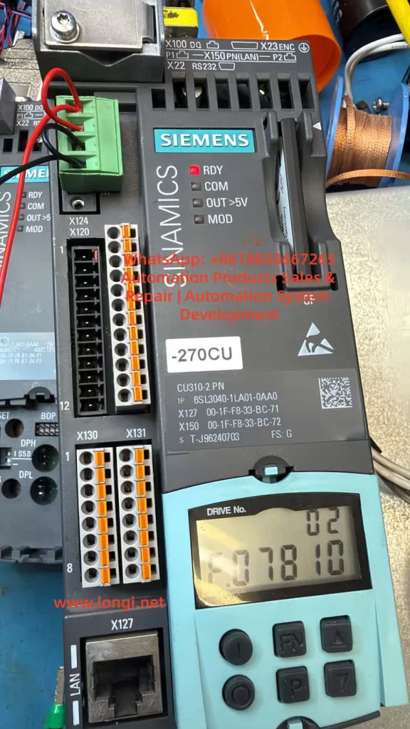
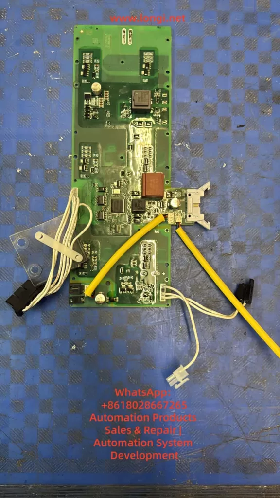
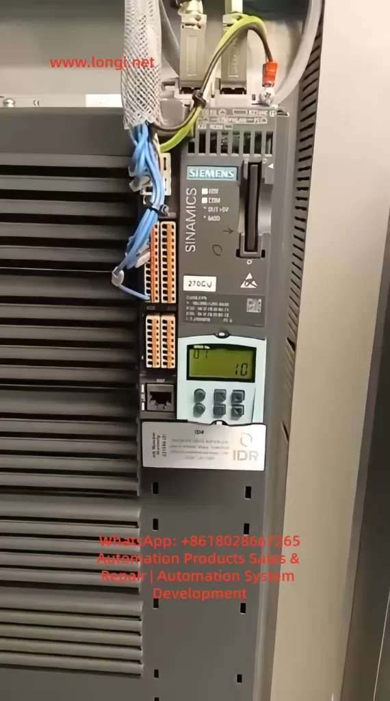
A common and often misunderstood scenario occurs when a drive initially reports fault F01112. After replacing the power PCB or rewriting the EEPROM data, the fault disappears, the drive powers up normally, and no errors are displayed. However, a new symptom appears: the RDY (Ready) LED flashes slowly, while the COM LED remains solid green. At the same time, an identical drive installed nearby shows both RDY and COM LEDs solid green.
At this point, many engineers mistakenly assume the EEPROM data is still incorrect or that the replacement board is incompatible. In reality, this situation usually indicates that the problem has moved from a hardware identity mismatch to a commissioning state issue. The drive now recognizes the hardware, but the system has not yet completed or exited its commissioning phase.
This article provides a structured analysis of this condition, explaining the transition from EEPROM-related faults to commissioning mode behavior, and outlines a practical method to restore the drive to full Ready status.
1. Understanding the Original Fault: F01112
The fault code F01112 is often loosely interpreted as an EEPROM failure or a defective power board. However, this is not technically precise. The real meaning of F01112 is:
The Control Unit does not accept the connected Power Module due to an identity or compatibility mismatch.
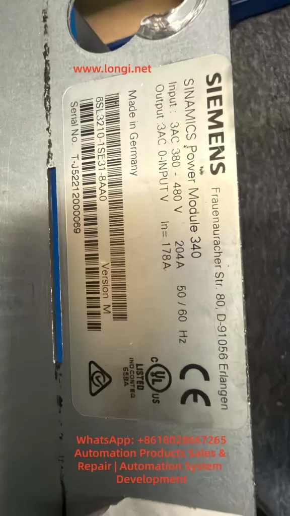
In the SINAMICS S120 system, the Control Unit (such as CU310-2 PN) performs an identity verification during startup. It reads electronic nameplate data stored in the EEPROM of the power section. This data includes not only identification but also system classification, version compatibility, and configuration attributes.
If the EEPROM contains data belonging to a different system—such as G120 instead of S120—the Control Unit will reject the module and issue F01112. Importantly, this rejection occurs even if the hardware itself is electrically sound.
2. Why S120 and G120 Cannot Be Interchanged
At a hardware level, some G120 and S120 components may appear physically compatible. However, their system architectures are fundamentally different.
- G120 is typically a more integrated system with predefined relationships between control and power components.
- S120 is modular, with flexible combinations of Control Units, Power Modules, Motor Modules, and communication interfaces.
The CU310-2 PN is designed specifically for S120 architecture and expects a compatible Power Module with corresponding identity data. A board carrying G120 identity data may function electrically, but will not be accepted logically within an S120 system.
3. What It Means When F01112 Disappears
When F01112 is successfully cleared after rewriting EEPROM data, this indicates that:
The Control Unit now accepts the identity of the Power Module.
This is a critical milestone. It confirms that the system has passed the hardware identity verification stage. Any remaining issues are no longer related to hardware compatibility, but rather to system configuration and operational state.
At this point, continuing to suspect EEPROM data is usually a misdirection. The focus must shift to the commissioning and parameter layers.
4. Interpreting the LED Status
The LED indicators provide useful but limited diagnostic information.
COM LED (Solid Green)
A solid green COM LED indicates that communication is active. This suggests that fieldbus or internal communication (such as DRIVE-CLiQ) is functioning correctly.
RDY LED (Slow Flashing Green)
A slowly flashing RDY LED, combined with no fault messages, typically indicates that:
- The drive is not in a fault condition
- The system is not yet fully ready for operation
- The drive is likely in a commissioning or pre-ready state
This is consistent with a system that has not completed initial setup or has not exited commissioning mode.
5. Why Commissioning Mode Appears After EEPROM Replacement
Rewriting the EEPROM resolves identity-related issues, but does not restore all system parameters. The S120 system requires a complete set of configuration data, including:
- Drive object definitions
- Motor data sets (MDS)
- Encoder data sets (EDS)
- Control modes
- Parameter interconnections (BICO)
- Communication mappings
If any of these are incomplete or inconsistent, the drive may automatically enter a commissioning state.
In effect:
The system recognizes the hardware but cannot confirm that it is fully configured for operation.
This leads to the observed behavior: no fault, but not fully Ready.
6. Distinguishing Hardware Issues from Commissioning State
A key skill in troubleshooting is distinguishing between these two categories.
Hardware Identity Issue
- Fault codes present (e.g., F01112)
- System refuses to initialize
- No progression beyond startup checks
Commissioning State Issue
- No active fault codes
- Communication operational
- RDY LED flashing
- System not enabling drive operation
Recognizing this distinction prevents unnecessary hardware interventions and focuses troubleshooting on parameter verification.
7. Critical Parameters to Check
LED indicators alone are insufficient for diagnosis. The following parameters must be checked:
r0002 – Drive State
This parameter indicates the current system status.
Typical relevant values:
- Indicates initial commissioning required
- Indicates commissioning mode not exited
p0009 – Control Unit Commissioning State
p0010 – Drive Object Commissioning State
p3900 – Commissioning Completion Trigger
In a fully operational system:
- p0009 = 0
- p0010 = 0
If p0010 is non-zero, the drive is still in commissioning mode.
To exit commissioning:
- Complete required parameter entries
- Execute commissioning completion (e.g., p3900)
- Save parameters and reboot
8. Using a Working Drive as Reference
In this case, the presence of an identical, fully operational drive is extremely valuable.
The most effective approach is:
- Read key parameters from the working drive
- Compare them with the repaired unit
- Identify differences in:
- Drive object configuration
- Motor and encoder data
- Commissioning parameters
- Communication setup
This direct comparison eliminates guesswork and provides a reliable path to resolution.
9. Recommended Troubleshooting Procedure
- Confirm that F01112 is fully cleared
- Observe LED states (RDY flashing, COM solid)
- Read r0002 to determine system state
- Check p0009 and p0010 for commissioning status
- If necessary, complete commissioning process
- Execute commissioning completion via p3900
- Save parameters to non-volatile memory
- Power cycle the drive
- Compare with a known-good system if available
10. Common Pitfalls
Many repair attempts fail at this stage due to:
- Continuing to suspect EEPROM after it is already correct
- Ignoring parameter-level diagnostics
- Relying solely on LED indicators
- Not saving parameters after modification
- Skipping commissioning completion steps
Understanding that the problem has shifted from hardware to system configuration is essential.
11. Key Takeaways for Engineers
This case highlights three important principles:
1. Hardware and System Layers Are Interdependent
Fixing hardware identity does not guarantee operational readiness.
2. Faults Evolve Through Stages
The problem moved from identity mismatch to commissioning state.
3. Parameter Analysis Is Critical
Final system readiness depends on correct parameter configuration.
12. Final Conclusion
When a SINAMICS S120 drive clears F01112 after EEPROM correction but shows a flashing RDY LED, the issue is no longer hardware-related. Instead, it indicates that the system has not completed or exited commissioning mode.
The correct approach is to verify system state parameters, complete any required commissioning steps, and ensure all parameters are saved properly.
Only when the drive exits commissioning mode and reaches a stable state will the RDY LED become solid green, matching the behavior of a fully operational unit.
In advanced drive systems like S120, successful repair requires not only restoring hardware functionality but also ensuring full system-level readiness.