Danfoss Holip HLP-NV Series User Manual Guide: Panel Operation, Parameter Backup, Terminal Forward Reverse Control, Potentiometer Reference and Fault Handling
Manual Reading Method
The Holip HLP-NV inverter is used on fans, pumps, conveyors, packaging machines, textile equipment and general speed-control machinery. Do not read the manual as a random parameter list. Use it as a commissioning map: panel status, parameter access, run command, speed reference, protection limits and fault record.
Different HLP models use different parameter numbers, so the exact code must be checked in the model-specific manual. The working logic is similar: the run command comes from keypad, terminals or communication; the speed reference comes from keypad, potentiometer, analog signal or bus; direction is decided by reverse input or direction command; protection depends on motor data, current limit, voltage, temperature and external interlock.
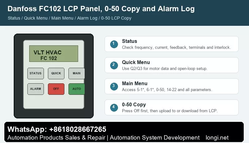
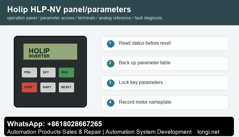
Operation Panel
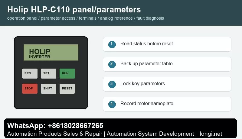
The common keypad includes PRG/ESC, SET/ENTER, RUN, STOP/RESET, SHIFT, UP and DOWN keys with LED or LCD display. Before editing, read frequency, current, DC bus voltage, direction, terminal state and fault code. Do not restore factory defaults before recording the original parameters, because many machines contain application-specific settings.
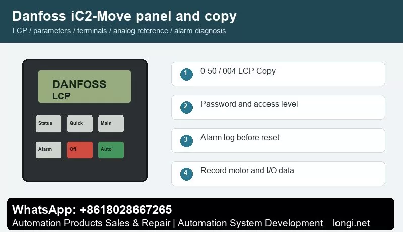
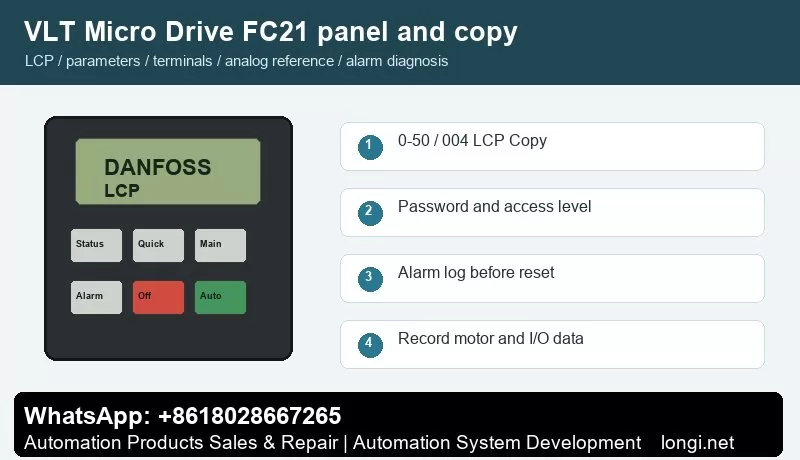
Record motor rated power, voltage, current, frequency and speed. Then record command source, frequency source, acceleration time, deceleration time, maximum frequency, minimum frequency, stop mode, terminal functions, analog input type and fault action. If the model supports parameter upload/download with a copy keypad, back up the parameters first. If not, photograph the key parameter pages.
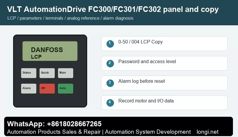
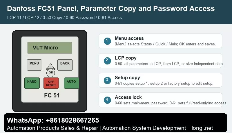
Parameter Copy, Access Restriction and Unlocking
Some HLP models support parameter transfer through an external keypad or copy unit. Stop the drive first, upload parameters to the keypad, then download them to a compatible replacement drive. If the rating, voltage class or software version is different, do not copy everything blindly. Recheck motor current, overload protection, maximum frequency, carrier frequency, braking and analog scaling.
Access restriction prevents wrong edits on site. Protect motor data, terminal functions, analog input type, maximum frequency, communication address and protection parameters. Operators should only start, stop, reset and view status. If the drive is locked, obtain the valid password or original commissioning record. If initialization is unavoidable, back up all readable parameters first.
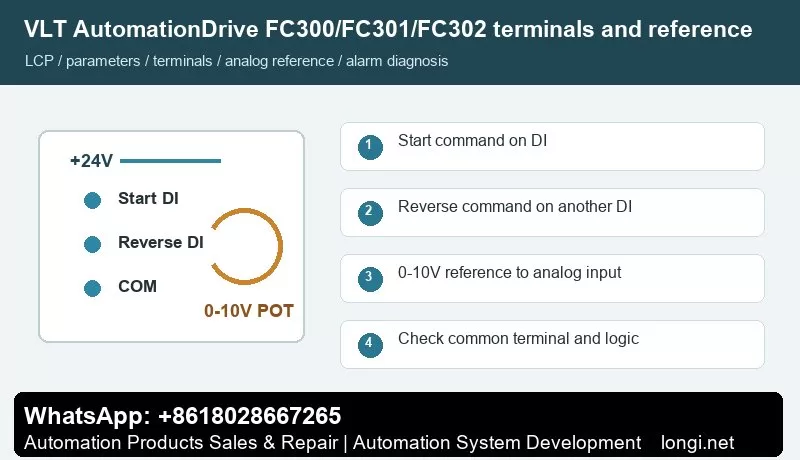
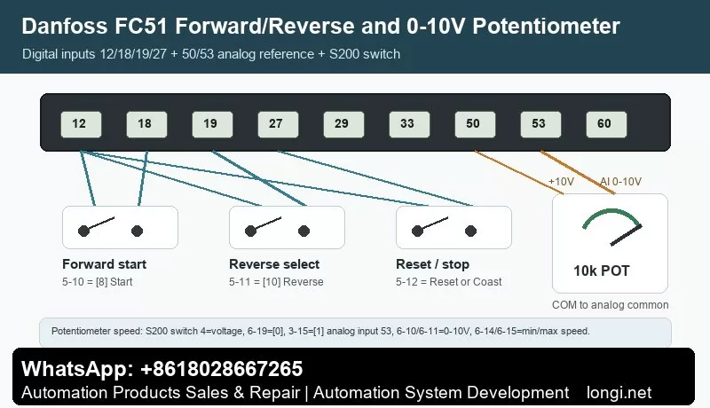
External Forward/Reverse Terminal Control
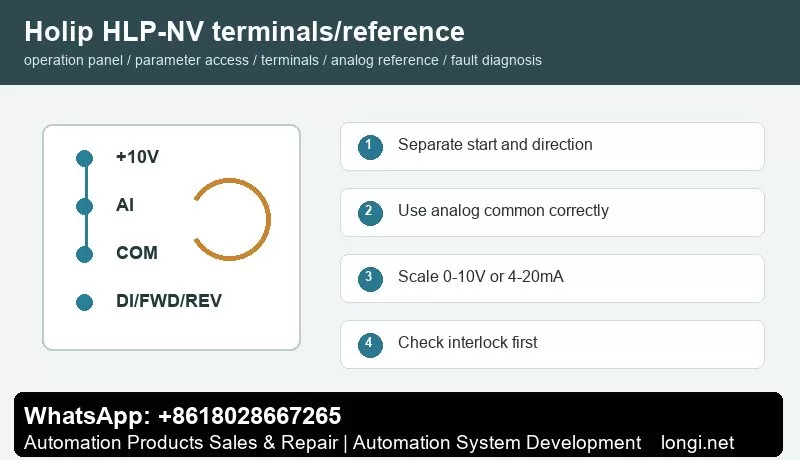
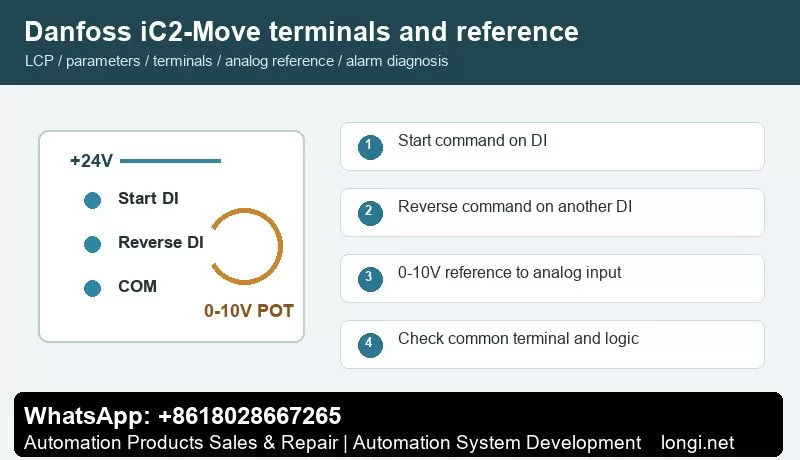
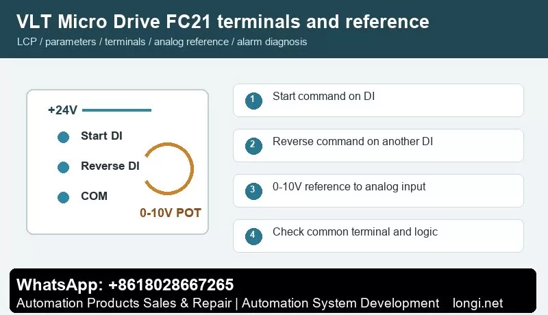
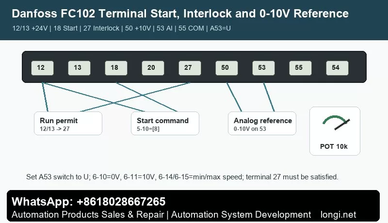
Before terminal control, confirm control supply, common terminal and input logic. A practical method is to use one digital input for start and another for reverse or direction selection. Buttons, selector switches, relays or PLC outputs may be used, but external power and the internal 24 V supply must not be mixed without a correct common reference.
Test with the motor unloaded or at low speed. First check the main circuit and motor insulation, then power on and observe terminal state on the keypad. Set one input as run command and another as reverse. Confirm that emergency stop, external fault, thermal relay, door switch and other interlocks are closed before running.
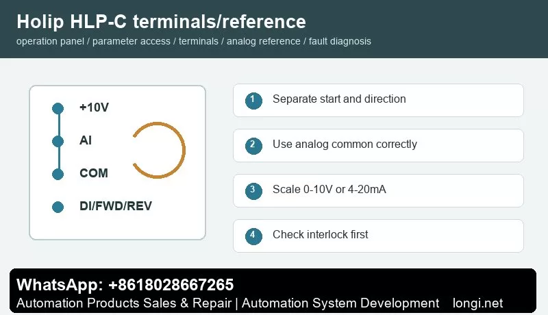
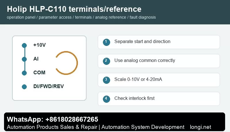
Potentiometer and Analog Speed Reference
A potentiometer normally uses three wires: +10 V to one end, analog common to the other end and the wiper to analog voltage input. If the site uses 4-20 mA pressure, temperature, tension or flow signal, select current input and scale low and high values according to the sensor range. Use shielded cable and keep analog wiring away from motor cables and contactor coils.
The key settings are reference source, analog input type, low scaling and high scaling. If the motor still runs at minimum potentiometer position, check minimum frequency and low scaling. If it cannot reach the target frequency, check maximum frequency and high scaling. If the speed fluctuates, check common terminal, shield grounding, potentiometer quality and analog filtering.
Fault Codes and Troubleshooting
- Overcurrent/OC: acceleration too short, jammed load, motor short, output ground fault or power module issue. Extend acceleration and test without load first.
- Overvoltage/OV: deceleration too short, high inertia, brake resistor or brake unit fault, or high mains voltage.
- Undervoltage/LU: low input voltage, contactor drop-out, rectifier issue or aging DC link capacitors.
- Overload/OL: incorrect motor data, long-term overload, poor cooling or mechanical resistance.
- Overtemperature/OH: blocked fan, dirty heatsink, high ambient temperature or insufficient installation clearance.
- Ground Fault/Short Circuit: wet motor winding, damaged output cable, contaminated terminals or burned contactor.
- External Fault: emergency stop, safety door, thermal relay, pressure switch or host interlock is open.
- Communication Fault: address, baud rate, parity, protocol or shield grounding mismatch.
Delivery Checklist
After repair, do not only check whether the motor rotates. Record final parameters, terminal wiring, frequency range, direction logic, alarm history, password policy and backup method. Keep both a paper parameter sheet and electronic photos for future replacement of inverter, keypad or control board.