1. Introduction: Why ERR29 Is Not Just a “Communication Fault Code”
In industrial inverter maintenance, ERR29 is often superficially categorized as a “communication fault.” However, in real-world GOOBELL G500 applications, this fault frequently represents a system-level control failure, involving:
- Control source configuration logic
- Communication state machine failure
- HMI (keypad) UI access locking mechanism
- Internal low-voltage control board instability
A typical field scenario shows the following behavior:
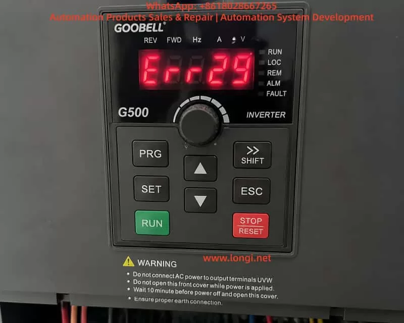
- ERR29 appears immediately after power-on
- No RUN command is required to trigger the fault
- Fault persists even after disconnecting RS485/PLC wiring
- Menu/parameter access is completely blocked
- STOP/RESET cannot restore access
This indicates that the issue is no longer a simple communication wiring problem, but a control architecture-level fault state.
2. Overview of GOOBELL G500 Control Architecture
To understand ERR29 correctly, the internal structure must be considered.
2.1 Power Circuit
- Three-phase rectifier stage
- DC bus (approx. 560–600V)
- IGBT inverter module
2.2 Control System (Core Layer)
- Main MCU (control logic processor)
- PWM generation module
- Protection detection circuits (overcurrent, overvoltage, undervoltage, overtemperature)
2.3 Human-Machine Interface (HMI)
- Keypad panel (PRG / ENT / ESC / STOP)
- Internal communication bus between keypad and main board
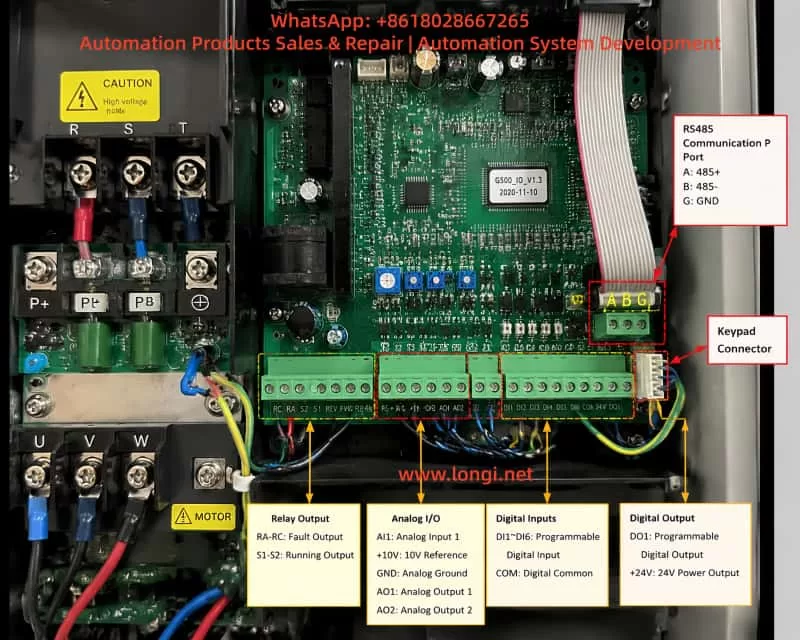
2.4 External Control Interfaces
- RS485 Modbus communication
- DI/DO terminal control
- PLC remote operation signals
3. Actual Meaning of ERR29 in G500 Systems
In GOOBELL G500-type platforms, ERR29 is generally defined as:
External communication loss or invalid communication control source
However, in engineering practice, the key point is:
❗ ERR29 is not only “communication failure”, but also a “control authority loss condition”
When the drive is configured as:
- RUN command source = COMMUNICATION (PLC/RS485)
- Frequency reference = communication-based
- External control enabled
If the inverter detects:
- No valid PLC RUN command
- Communication not established
- Incorrect station address or baud rate
It enters:
Communication Fault Protection State (COMM FAULT LOCK)
4. Key Abnormal Symptoms in This Case
This case exhibits three critical symptoms:
4.1 ERR29 appears immediately after power-on
This indicates:
- Fault occurs during initialization phase
- Communication system fails at startup stage
4.2 Fault remains even after communication disconnection
This confirms:
- External communication wiring is not the root cause
- Internal logic state remains locked
4.3 Menu/parameter access is completely unavailable
This is the most critical symptom:
The UI system is locked at the fault display level.
5. Fault Priority Lock Mechanism in G500
The GOOBELL G500 inverter uses a fault priority display system:
When communication control mode is active and communication is lost → the system enters a fault latch mode.
Characteristics:
- Fault screen is permanently displayed (ERR29)
- Keypad menu entry is blocked
- RESET function is partially or fully ineffective
- Control state machine is frozen awaiting communication recovery
6. Root Cause Analysis of This Case
Based on full isolation testing (communication removed, reset attempted, power cycling), the fault can be narrowed down to three categories:
6.1 Control Mode Latch State Not Cleared (High Probability)
If the drive is configured as:
- Communication control mode enabled
- PLC not responding at startup
The system enters a latched fault state where:
Even after communication is removed, the internal state remains in “waiting for communication” mode.
Result:
- Menu access remains blocked
- UI layer cannot be entered
6.2 Keypad-to-Mainboard Communication Failure (Medium Probability)
The keypad is not independent; it communicates with the main control board.
Possible issues:
- Internal communication bus failure
- Loose keypad cable connection
- Keypad IC malfunction
Symptoms:
- Display is normal
- Keys are unresponsive or partially responsive
- Menu cannot be accessed
6.3 Low-Voltage Control Power Instability (Medium-Low Probability)
Control board requires stable low-voltage rails:
- +5V logic supply
- +15V driver supply
If +5V is unstable:
- MCU cannot properly execute state transitions
- UI logic becomes frozen
- Fault state cannot be cleared
7. Why “Communication Disconnected but Still Faulty” Is Critical
In normal communication faults:
| Action | Expected Result |
|---|---|
| Disconnect RS485 | Fault clears |
| Switch to local mode | Menu accessible |
However, in this case:
❗ ERR29 persists even after full isolation
This indicates:
- External control dependency has been removed
- Internal state machine remains locked
8. Field Diagnostic Procedure (Engineering Standard)
Step 1: Full isolation of external control
- Disconnect RS485 (A/B/SG)
- Remove PLC control wiring
- Keep only main power input
Step 2: Forced reset attempt
- Hold STOP/RESET ≥ 5 seconds
- Repeat multiple times
Step 3: UI access verification
Check if menu can be accessed:
- PRG
- Parameter groups
- Monitoring mode
Step 4: Keypad function test
Test all keys:
- STOP/RESET
- PRG/MENU
- ENT/ESC
- Arrow keys
Step 5: Control voltage measurement
Measure control board supply:
- +5V (4.8–5.1V)
- +15V
- Ground stability
9. Fault Classification Model
Level 1: External communication issue
✔ Already excluded
Level 2: Control mode latch state
✔ Most likely cause
Level 3: Keypad/HMI communication fault
✔ Possible
Level 4: Main control board hardware fault
✔ Requires confirmation
10. Recommended Repair Strategy
Option 1: Fast recovery method
- Disconnect communication wiring
- Switch to local control mode
- Perform forced reset
Applicable only if menu access is possible
Option 2: Module replacement test (recommended)
- Replace keypad panel
- Cross-test UI functionality
Option 3: Mainboard-level diagnosis
- Check +5V logic supply
- Verify MCU operation
- Inspect EEPROM/state memory lock
11. Key Engineering Insights
This case highlights an important field principle:
ERR29 on GOOBELL G500 is not always a simple communication fault; when accompanied by “no menu access,” it often indicates an internal control-state lock condition rather than an external wiring issue.
Key takeaways:
- ERR29 is a system-level fault, not only communication-related
- “No menu access” is more critical than the fault code itself
- Disconnecting communication without recovery indicates internal logic lock
- Diagnosis must shift from external wiring to internal control state
12. Conclusion
The GOOBELL G500 ERR29 “power-on immediate lockout with no menu access” case represents a multi-layer control system failure involving:
- Communication control configuration
- Internal fault latch mechanism
- UI access restriction logic
- Possible keypad or control board communication failure
The resolution is not limited to parameter adjustment, but requires a structured approach:
- Control source recovery
- Fault latch clearing
- UI communication restoration
- Hardware validation when necessary