Posted on

Technical Analysis and Troubleshooting of the “StP” Display After Replacing the Control Boards and Power Module in a Daikin SUT00 Servo-Hydraulic Unit

Introduction

The Daikin SUT00 Super Unit is a servo-hydraulic power system designed primarily for injection molding machines, die-casting machines, and other industrial forming equipment. It is not a conventional fixed-displacement hydraulic power pack, nor is it simply a general-purpose inverter. Instead, it is an integrated closed-loop electro-hydraulic system consisting of an IPM permanent-magnet servo motor, gear pump, pressure sensor, rotary encoder, servo controller, power module, current detection circuit, and hydraulic control components.

The SUT00 system regulates pump output flow by controlling motor speed. At the same time, it uses pressure feedback to perform closed-loop pressure control. Compared with a traditional hydraulic system using a continuously running induction motor, fixed-displacement pump, proportional valve, and relief valve, the SUT00 can adjust motor output according to the actual pressure and flow demand. This significantly reduces energy consumption and oil temperature during standby, pressure-holding, and low-load operation.

During repair work, the controller may require replacement of the control board, power-supply board, current detection board, driver board, or IPM power module. After these components are replaced, technicians often encounter a panel indication reading “StP.”

Because “StP” is not a conventional numerical alarm code, it is often misinterpreted as a controller initialization failure, software mismatch, missing program, incompatible power module, or defective replacement board. In many cases, however, “StP” simply means that the controller is in the Stop state. The controller has completed its basic power-up process but has not received a valid pump start command.

Nevertheless, after board replacement, “StP” should not be cleared by blindly shorting terminals or forcing the pump to start. The technician must verify the start/stop digital input, parameter settings, board compatibility, pump-controller matching parameters, pressure and flow commands, Ready status, encoder feedback, pressure sensor feedback, and thermistor circuit before attempting operation.

This article explains the meaning of “StP,” the start logic of the Daikin SUT00, the parameters that must be checked after controller replacement, the correct troubleshooting sequence, and the precautions required during the first trial run.
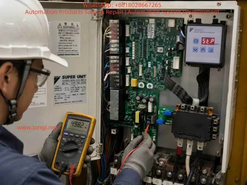

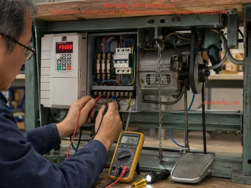
A technician inspecting a Daikin SUT00 servo-hydraulic control unit inside an industrial electrical cabinet. The cabinet door is open, showing the Daikin PMC Power Motion Controller display with a red “StP” stop status, internal control boards, power board, IPM module, wiring terminals, and motor connections. The technician uses a digital multimeter to measure voltage while troubleshooting the controller after replacing electronic components. The image illustrates industrial maintenance, electrical diagnosis, and troubleshooting of a servo hydraulic system.

1. Basic Construction and Operating Principle of the Daikin SUT00 System

The Daikin SUT00 series mainly consists of the following components:

  1. Three-phase servo controller
  2. IPM permanent-magnet synchronous motor
  3. Gear-type hydraulic pump
  4. Motor rotary encoder
  5. Hydraulic pressure sensor
  6. Motor thermistor
  7. Motor cooling fan
  8. Main control board
  9. Driver and power-supply board
  10. IPM intelligent power module
  11. Current detection board
  12. External pressure, flow, and start/stop command interfaces

The machine controller normally sends two analog signals to the SUT00:

  • Pi: pressure command
  • Qi: flow-rate command

The SUT00 also sends monitor signals back to the machine controller:

  • Po: pressure monitor output
  • Qo: flow-rate monitor output

During operation, the controller calculates the target motor speed according to the Qi flow command. The encoder detects the actual motor speed, and the controller regulates the U, V, and W phase currents through the IPM power module so that the motor reaches the commanded speed.

As the hydraulic pressure rises and approaches the Pi pressure command, the controller transitions from flow control to pressure-limiting or pressure closed-loop control. It then reduces motor speed automatically to prevent the actual pressure from exceeding the target pressure.

Therefore, the SUT00 does not merely output a fixed three-phase frequency. It simultaneously evaluates:

  • Pressure command
  • Flow command
  • Pressure feedback
  • Motor speed feedback
  • Motor current
  • Motor temperature
  • Controller temperature
  • Digital start/stop input
  • External interlock conditions

The SUT00 controller uses a three-phase 380–440 VAC power supply. The motor cooling fan usually requires an additional single-phase 215–245 VAC power supply. For the SUT00S13018 model, the rated maximum flow is 130 L/min and the maximum operating pressure is 17.6 MPa.


2. What Does “StP” Actually Mean?

“StP” is generally an abbreviation of Stop. It indicates that the pump motor is currently in the stopped state.

This is fundamentally different from an alarm.

A real fault alarm normally appears as a specific alarm number or code. It may also cause the Ready output to turn OFF and prohibit motor operation. By contrast, “StP” mainly indicates that the controller is not currently executing a pump run command.

When the operation panel displays “StP” steadily, it normally suggests that:

  • The control-board CPU has started;
  • Communication between the panel and the main control board is functioning;
  • At least part of the low-voltage control power supply is operating;
  • No immediate severe hardware alarm has been detected at power-up;
  • The motor has not yet been enabled to run.

Therefore, “StP” by itself is not direct evidence of a failed IPM module or defective control board.

However, “StP” also does not prove that the controller is fully functional. Since the controller has not yet driven the motor, some faults may only appear after a valid start command is received, including:

  • Encoder fault
  • Motor phase loss
  • IPM driver fault
  • Current detection abnormality
  • Motor overcurrent
  • DC-bus undervoltage
  • IPM protection trip
  • Speed deviation
  • Abnormal pressure rise
  • Motor thermistor fault

For this reason, “StP” should be interpreted as the controller is stopped and waiting, not as confirmation that the repair has been completed successfully.
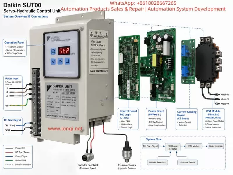

Technical exploded-view illustration of a Daikin SUT00 servo-hydraulic control unit showing the system architecture and internal components. The diagram highlights the operation panel displaying “StP” stop status, control board, power board, current sensing board, Mitsubishi IPM power module, DI1 start signal, P00 control logic, encoder feedback, pressure sensor, three-phase motor connections, and power input terminals. The infographic explains the connection structure and troubleshooting points of the Daikin servo hydraulic controller system.

3. The SUT00 Is Not Normally Started from the Panel

The operation-panel keys are mainly used for:

  • Switching monitor modes
  • Viewing operating data
  • Entering parameter-setting mode
  • Viewing alarm history
  • Modifying permitted parameters

Unlike a general-purpose inverter, the panel does not normally provide a direct RUN key for starting the hydraulic pump. The pump motor is primarily started and stopped through digital input DI1.

Parameter P00, identified as the DI_A start/stop signal switching parameter, determines the DI1 logic:

P00 settingDI1 OFFDI1 ON
0Pump stopPump run
1Pump runPump stop

When P00 is set to 0, DI1 ON means Run. When P00 is set to 1, the logic is reversed and DI1 OFF means Run.

This is one of the most common reasons for an StP indication after a control-board replacement.

For example, assume the original controller used:

P00 = 0

The machine PLC sends 24 V to DI1 whenever the hydraulic pump is required to run.

If the replacement control board contains:

P00 = 1

the same 24 V input is interpreted as a stop command instead of a run command.

From the PLC side, the pump-start output appears to be active. From the SUT00 controller side, however, the stop condition remains valid. The panel therefore continues to display “StP.”

For this reason, it is not sufficient to verify that 24 V exists at the DI1 terminal. The P00 input logic must also be checked.


4. Main Reasons for an “StP” Display After Board Replacement

4.1 No DI1 Start Signal Is Reaching the Controller

An injection molding machine normally does not start the hydraulic pump immediately after power-up. Several interlock conditions may have to be satisfied first, such as:

  • Emergency stop reset
  • Safety door closed
  • Main PLC running normally
  • Oil level switch normal
  • Oil temperature normal
  • Motor thermal protection normal
  • Servo controller Ready signal present
  • No hydraulic-system alarm
  • Machine in an operating mode that permits pump start
  • Pump-start pushbutton or command activated

If any required interlock remains unsatisfied, the PLC may not energize DI1.

Common field problems include:

  • DI1 wire omitted during reassembly
  • Connector not fully inserted
  • Ribbon cable misaligned
  • DICOM not connected
  • External 24 VDC supply missing
  • Wrong DI1 polarity
  • Failed PLC output relay
  • Different terminal definition between original and replacement board
  • Loose terminal screw
  • Bent connector pin

Therefore, when “StP” appears after board replacement, the first task is to determine whether the controller is actually receiving the DI1 signal.


4.2 P00 Does Not Match the Original Controller

A replacement control board may still contain factory-default parameters, or it may have been removed from another machine.

Even if the board number appears identical, its stored parameters may not be suitable for the current machine. If P00 differs from the original setting, the start logic will be reversed directly.

The technician should enter parameter-setting mode, read the current P00 value, and compare it with:

  • The original controller parameter record
  • The machine electrical schematic
  • PLC output logic
  • Actual DI1 voltage changes
  • Machine commissioning records

If no original documentation is available, the DI1 monitor status and machine start behavior can be used for diagnosis. However, parameters should not be changed casually and followed immediately by high-pressure operation.


4.3 Original Parameters Have Not Been Restored

A Daikin SUT00 controller is not fully interchangeable merely because the replacement board has the same appearance or board number.

During factory commissioning, the controller is configured according to:

  • Actual pump displacement
  • Pressure sensor characteristics
  • Analog command range
  • Hydraulic response
  • Machine motion requirements
  • Motor and controller calibration

If the original parameters are not restored after controller replacement, the system may run but exhibit serious performance problems, including:

  • Insufficient maximum flow
  • Failure to build pressure at low flow
  • Incorrect pressure indication
  • Actual pressure higher than commanded
  • Abnormal motor speed
  • Unstable pressure holding
  • Slow response
  • Pressure shock
  • Speed alarm
  • Incorrect flow scaling
  • Machine motion speed different from the original condition

The manual specifies that original controller parameters should be restored after controller replacement. In particular, H15, H30, and P07 are closely related to the pump, pressure sensor, and controller matching calibration.


4.4 The Ready Condition Has Not Been Established

After power-up, the controller must complete internal initialization, including:

  • Control power stabilization
  • CPU program execution
  • Memory reading
  • Initial sensor checks
  • DC-bus status detection
  • Protection-circuit self-check
  • I/O initialization

Only when the controller reaches the permissible operating state does the Ready output turn ON.

If Ready is not established, the external PLC may refuse to send the pump-start command. This creates a sequence such as:

  1. SUT00 controller is not Ready;
  2. PLC does not output pump start;
  3. Controller remains in StP;
  4. Machine controller waits for the hydraulic-unit Ready signal.

In this case, the technician must not focus only on DI1. The DO1 Ready output, alarm history, and internal monitor values must also be checked.


4.5 Compatibility Problems Between the Control Board, Driver Board, and IPM Module

The power module shown in the repair photographs is a Mitsubishi Electric PM100RL1A120 series IPM module. Such modules typically integrate power semiconductor devices, gate-drive protection, and fault-feedback functions.

When replacing an IPM module, the following points must be confirmed:

  • Exact complete model number
  • Voltage rating
  • Current rating
  • Pin assignment
  • Module revision compatibility
  • Correct mounting screw torque
  • Good thermal contact with the heat sink
  • Uniform thermal compound thickness
  • Correct insulation-sheet condition
  • Driver connector installed in the correct orientation
  • No shifted control pins
  • Correct DC positive and negative bus connections
  • Correct U, V, and W output connections

If the IPM module or driver board is incompatible, the controller may remain normal while stopped but trip immediately when a start command is applied.

Therefore, static checks must be completed before DI1 is enabled.


5. Parameters That Must Be Checked After Controller Replacement

5.1 P00: Start/Stop Input Logic

P00 determines whether DI1 ON or DI1 OFF represents Run.

This is the first-priority parameter when the panel remains in “StP.”


5.2 P05: VMAX Analog Command Full-Scale Voltage

The SUT00 normally uses 0–10 V pressure and flow commands, but the actual full-scale input voltage is parameterized.

An incorrect VMAX setting may cause:

  • A 10 V command to produce less than full output
  • A small voltage to produce excessive pressure or flow
  • Pressure not proportional to the machine setting
  • Severe flow-scaling error

5.3 P06: PMAX Maximum Pressure Scaling

P06 defines the maximum pressure corresponding to the full-scale pressure command.

Although the SUT00S13018 has a rated maximum operating pressure of 17.6 MPa, the actual machine may be configured for a lower maximum pressure due to:

  • Hydraulic circuit limitations
  • Mold-protection requirements
  • Machine design
  • Process requirements

The system should never be tested immediately at 17.6 MPa simply because that is the model’s maximum rating.


5.4 P07: QMAX Maximum Flow Scaling

P07 defines the maximum flow corresponding to the full-scale flow command.

The SUT00S13018 is rated for up to 130 L/min, but the pump and controller are factory-matched and calibrated. The P07 value stored in a spare controller may not be correct for the installed pump assembly.

The manual requires the original P07 value to be written into the replacement controller.


5.5 H15: Q_EV Flow Correction Coefficient

H15 compensates for actual pump-output characteristics, particularly during low-flow operation and pressure build-up.

An incorrect H15 value may cause:

  • Difficulty building pressure at low flow
  • Unstable pressure holding
  • Motor rotation without sufficient pressure rise
  • Low-flow pressure-rise alarm
  • Difference between calculated and actual pump output

The manual indicates that H15 may require adjustment if abnormal pressure rise occurs at a low flow setting after pump replacement or commissioning.


5.6 H30: PS_G Pressure Sensor Gain

H30 calibrates the pressure sensor feedback.

If H30 is incorrect, there may be a difference among:

  • Actual hydraulic pressure
  • SUT00 panel pressure indication
  • Machine HMI pressure indication
  • Po pressure monitor output

If the pressure sensor gain is too low, the controller may believe pressure is insufficient and continue increasing motor torque, causing excessive actual pressure.

If the gain is too high, the controller may reduce speed too early and fail to reach the required pressure.

After replacing the pressure sensor or controller, H30 must be restored correctly or recalibrated. The manual recommends comparing the controller reading with an accurate pressure gauge in pressure-control operation.


5.7 H21 to H28 Must Not Be Copied Directly

The manual specifically states that H21 to H28 are controller-specific calibration values.

Therefore, after replacing the controller:

  • Machine operating parameters may be restored;
  • H15, H30, and P07 may be transferred as required for pump matching;
  • H21 to H28 must not be copied from the old controller into the replacement controller.

Doing so may corrupt the replacement controller’s own current-detection, hardware-calibration, or drive-compensation data.


6. Standard Troubleshooting Procedure When “StP” Is Displayed

Step 1: Confirm the Unit Model and Replacement Component Information

Record the complete nameplate and board information, including:

  • SUT00S13018-10YA-N0218
  • Controller manufacturing number
  • Pump and motor manufacturing number
  • Control-board number
  • Power-board number
  • IPM module model
  • Current detection board number
  • Software revision
  • Hardware revision

The Daikin manual states that the motor-pump assembly and controller are tested as a matched pair before shipment. In principle, the controller and pump assembly should have the same manufacturing number.

When using replacement boards, at minimum confirm that the product series, power rating, software version, motor type, and feedback method are compatible.


Step 2: Perform Static Checks with Power Disconnected

Disconnect the three-phase power supply and wait at least five minutes for the DC-bus capacitors to discharge.

Then check:

  1. No short circuit between the DC-bus terminals P1 and P2;
  2. U, V, and W phase resistance characteristics are approximately symmetrical;
  3. Diode-test characteristics from U, V, and W to the positive and negative DC bus are symmetrical;
  4. U, V, and W are insulated from ground;
  5. Motor winding resistances are balanced;
  6. Motor insulation to ground is acceptable;
  7. IPM module mounting surface is flat;
  8. Mounting screws are secure;
  9. Current detection board is installed in the correct direction;
  10. All connectors are fully inserted;
  11. Ribbon-cable contacts are clean;
  12. No bent pins, cracked solder joints, or burn marks are present.

A standard multimeter can only provide a preliminary assessment. It cannot prove that the IPM module is dynamically healthy under load.


Step 3: Power Up Without Immediately Starting the Pump

During the first power-up after repair, do not immediately allow the PLC to issue a run command.

Observe:

  • Whether the panel powers up normally;
  • Whether “StP” is displayed;
  • Whether any other alarm appears;
  • Whether the control board produces abnormal sound;
  • Whether the power-supply board heats abnormally;
  • Whether the IPM module heats rapidly;
  • Whether the DC-bus voltage is normal;
  • Whether the Ready output is established;
  • Whether the cooling fans operate as designed.

If a serious alarm appears immediately, resolve that alarm before any attempt to start the motor.


Step 4: Check the Actual DI1 Status

Measure the voltage between DI1 and DICOM with a multimeter.

Record the voltage under both conditions:

  • Machine stopped;
  • Pump-start command activated.

If the voltage does not change, the problem is most likely in the external control circuit.

Check:

  • 24 VDC power supply
  • PLC output
  • Interposing relay
  • Terminal wiring
  • Emergency-stop circuit
  • Safety-door circuit
  • Ready interlock
  • DICOM connection

If the voltage changes but the panel still displays “StP,” enter monitor mode and verify whether the controller internally detects the DI1 change.


Step 5: Read P00

Confirm that P00 matches the external DI1 logic.

For example:

  • If DI1 changes from 0 V to 24 V when the machine requests pump operation, P00 is commonly set to 0;
  • If DI1 is energized during stop and released during Run, P00 may be set to 1.

The correct setting must be determined from the original circuit and actual input status, not from assumption alone.


Step 6: Check Pressure and Flow Commands

Even if DI1 is in the Run state, the system may remain in a low-output standby condition if both Pi and Qi are zero or near zero.

The manual describes a standby condition when the pressure and flow commands are low. Parameter P15 BIAS defines the standby pressure behavior.

The following monitor values should be checked:

  • Pi pressure command voltage
  • Qi flow command voltage
  • Pressure feedback
  • Flow feedback
  • Actual motor speed
  • Digital input status

If the machine has issued a motion command but Pi and Qi remain at 0 V, inspect the analog signal wiring and analog common connection.


Step 7: Restore the Original Controller Parameters

The best method is to read and record all parameters from the original controller before removal.

If the original controller is completely damaged, search for:

  • Machine manufacturer parameter sheet
  • Injection molding machine commissioning records
  • Another identical operating machine
  • Previous repair records
  • Parameter photographs
  • PLC or HMI process-setting records

The parameters should be divided into three categories.

Machine Parameters That May Be Restored

These include P00, P05, P06, P07, P15, and pressure- and flow-response parameters.

Pump-Matching Parameters That Must Be Restored

These include H15, H30, and P07.

Controller-Specific Parameters That Must Not Be Copied

These include H21 to H28.


7. Low-Risk Procedure for the First Trial Run

Only after the previous checks are completed should the unit be started.

7.1 Place the Hydraulic Circuit in an Unloaded Condition

Avoid immediately performing:

  • High-pressure clamping
  • Injection
  • Ejector operation
  • High-pressure mold locking
  • Driving a cylinder against its mechanical stop
  • Long pressure-holding operation

Where possible, select an unloaded return path or a low-load machine movement so that the pump will not immediately build high pressure.


7.2 Use Low Pressure and Flow Commands

For an initial trial, use low command values, such as:

  • Pressure command: approximately 0.5–1.0 V
  • Flow command: approximately 0.3–0.5 V

The exact values must be selected according to the machine’s actual command scaling.

Do not apply 10 V pressure and 10 V flow commands during the first test. If H30, P06, P07, or H15 is incorrect, the result may be uncontrolled pressure or motor speed.


7.3 Perform a Short Jog Test

The first run may be limited to approximately one or two seconds.

Observe:

  • Whether the motor rotates smoothly;
  • Whether there is severe vibration;
  • Whether the pump produces a sharp cavitation sound;
  • Whether motor direction is correct;
  • Whether pressure rises abnormally quickly;
  • Whether the three-phase currents are balanced;
  • Whether an alarm appears immediately;
  • Whether the IPM module heats abnormally.

Stop immediately if any abnormal condition is detected.


7.4 Confirm Pump Rotation Direction and Oil Suction

If the U, V, and W phase sequence or the encoder matching relationship is incorrect, the motor may not operate correctly in closed loop.

Reverse pump rotation may cause:

  • Failure to draw oil
  • No pressure rise
  • Abnormal pump noise
  • Pump damage
  • Incorrect encoder speed direction
  • Speed deviation or overcurrent alarm

Motor rotation alone does not confirm correct pump direction.


7.5 Verify Pressure Feedback Accuracy

Use a mechanical pressure gauge or a calibrated electronic pressure gauge to compare:

  • Actual hydraulic pressure
  • SUT00 panel pressure
  • Machine HMI pressure
  • Po pressure monitor output

If the difference is significant, do not continue increasing pressure. Check:

  • Pressure sensor
  • Pressure sensor power supply
  • Signal wiring
  • H30 setting
  • Analog monitor scaling
  • Pressure sensor installation point

8. Common Incorrect Repair Actions and Their Risks

8.1 Shorting DI1 Immediately After Seeing “StP”

If P00 is configured for reverse logic, shorting DI1 may not start the pump. More importantly, forcing DI1 can bypass machine safety logic and cause unexpected movement.

The correct method is to read the DI1 state and confirm P00 first.


8.2 Failing to Restore Parameters After Board Replacement

The controller may appear to run, but the hydraulic performance can differ significantly from the original machine.


8.3 Copying All H Parameters from the Old Controller

H21 to H28 are specific to the replacement controller and must not be overwritten with values from the old board.


8.4 Applying Maximum Pressure and Flow During the First Run

This amplifies any error in pressure feedback, flow scaling, or current detection and may damage the replacement IPM module again.


8.5 Ignoring the Encoder Circuit

The SUT00 uses encoder feedback for speed closed-loop control. A loose connector, missing encoder supply, abnormal A/B phase signals, or incorrect direction can cause serious speed-control faults.


8.6 Ignoring the Motor Thermistor and Cooling Fans

The motor thermistor, controller fan, and motor cooling fan are important protection components. A missing fan supply may not cause an immediate power-up fault but can result in overheating during operation.


8.7 Applying a Megohmmeter Directly to Electronic Circuits

A megohmmeter can damage:

  • Encoder
  • Pressure sensor
  • Control board
  • IPM control terminals
  • Analog input circuits

Insulation testing should be performed only on the motor windings and power cables after electronic components have been properly disconnected.


9. Criteria for Confirming a Successful Repair

A repair should not be considered complete merely because the panel exits “StP.”

A satisfactory result should include all of the following:

  1. No abnormal alarm at power-up;
  2. Ready output operates correctly;
  3. DI1 status corresponds to the external start command;
  4. P00 logic is correct;
  5. “StP” disappears when valid run conditions are satisfied;
  6. Motor runs smoothly at low speed;
  7. Encoder feedback is stable;
  8. Three-phase current is reasonably balanced;
  9. Pressure command agrees with actual pressure;
  10. Flow command produces the expected speed response;
  11. No abnormal noise or vibration;
  12. IPM module temperature rise is normal;
  13. Motor and controller cooling fans operate correctly;
  14. Low-pressure, low-flow, and pressure-holding operation are stable;
  15. High-pressure and high-flow tests are introduced gradually without alarms;
  16. Machine motion speed returns to the original performance;
  17. Final parameter values are recorded and backed up.

Only after these conditions are met can the repaired SUT00 unit be considered technically reliable.


10. Conclusion

When a Daikin SUT00 servo-hydraulic control unit displays “StP” after replacement of the control board, power-supply board, current detection board, or IPM module, the indication normally means that the controller is in the Stop state. It does not automatically indicate a hardware fault.

The most common causes are:

  • No DI1 start command
  • Incorrect external 24 V or DICOM wiring
  • P00 start logic different from the original controller
  • Ready condition not established
  • PLC safety interlock not satisfied
  • Original controller parameters not yet restored

The correct solution is not to short terminals blindly or continue replacing power modules. The technician should follow a structured sequence:

static inspection → power-up initialization → Ready verification → DI1 monitoring → P00 verification → parameter restoration → low-risk jog test → pressure and flow calibration

Particular attention must be paid to H15, H30, and P07. These parameters are associated with flow correction, pressure sensor gain, and maximum flow scaling. At the same time, H21 to H28 are controller-specific calibration values and should not be copied from the old controller into the replacement controller.

The Daikin SUT00 is a multi-loop servo-hydraulic system integrating pressure, flow, speed, and current control. It should not be diagnosed using only the logic of a standard contactor-driven motor or general-purpose inverter. Reliable recovery requires correct power hardware, valid sensor feedback, correct digital start logic, proper analog command scaling, and accurate control parameters. Only when all of these elements are verified can the original pressure accuracy, motion speed, operating stability, and long-term reliability of the machine be restored.
Posted on

AnyHz FST-650 Inverter Err20 Encoder Fault Analysis and Complete Troubleshooting Guide

Introduction

With the rapid development of industrial automation, variable frequency drives (VFDs) have evolved from simple motor speed regulators into intelligent drive systems integrating motor control, speed feedback, torque management, communication functions, and advanced fault diagnosis.

In applications requiring high speed accuracy and dynamic response, such as machine tools, cranes, textile equipment, printing machinery, packaging lines, and automated production systems, closed-loop vector control with encoder feedback has become increasingly common.

The AnyHz (Foster Technology) FST-650 series is a high-performance vector control inverter that supports multiple control modes, including:

  • V/F control;
  • Sensorless vector control;
  • Closed-loop vector control with encoder feedback.

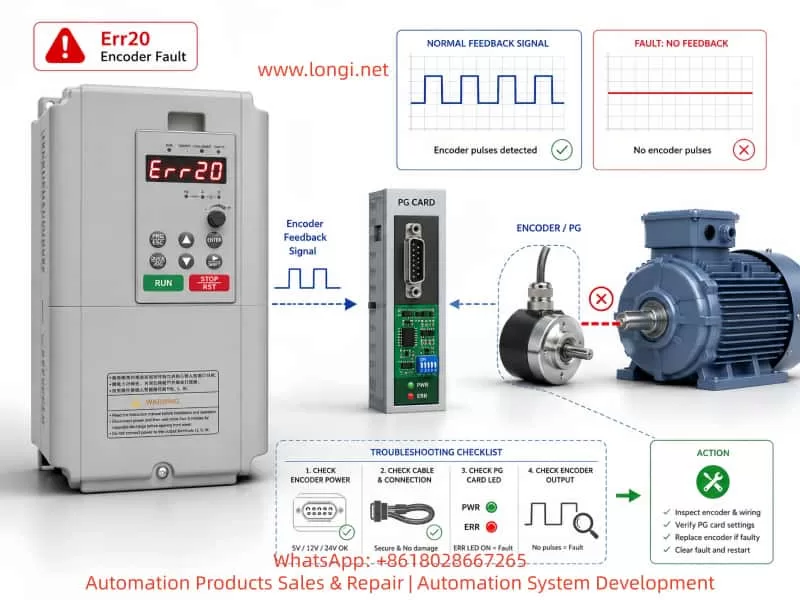
When the FST-650 displays the fault code Err20, the inverter has detected an abnormality in the encoder feedback system.

The meaning of Err20 is:

Err20 = Encoder Fault / PG Card Fault

However, in practical maintenance work, Err20 does not always mean that the encoder itself is damaged. Many real-world cases are caused by:

  • Incorrect control mode selection;
  • Wrong encoder parameter settings;
  • Encoder wiring problems;
  • Missing encoder power supply;
  • PG card failure;
  • Incorrect replacement configuration.

This article provides a detailed analysis of the working principle behind Err20, common causes, diagnostic procedures, and repair methods to help engineers quickly troubleshoot AnyHz FST-650 encoder-related faults.


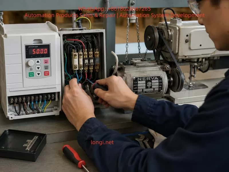
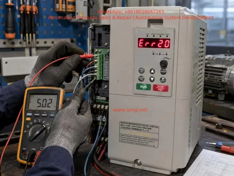
Technician troubleshooting AnyHz FST-650 inverter Err20 encoder fault using a multimeter to check PG card and encoder feedback wiring in an industrial maintenance workshop

1. Working Principle of Err20 Fault in FST-650 Inverter

1.1 The Role of Encoder Feedback in Closed-Loop Vector Control

A conventional inverter operating in open-loop mode controls the motor based on the output frequency and voltage.

For example:

  • Frequency command: 50Hz;
  • Output voltage calculated according to motor model;
  • Motor speed estimated by inverter algorithm.

This type of control does not require an encoder.

However, in closed-loop vector control, the inverter must continuously know:

  • Actual motor speed;
  • Rotor position;
  • Rotation direction;
  • Speed deviation.

Therefore, an encoder is installed on the motor shaft.

The control process is:

Speed Command
      ↓
Vector Control Algorithm
      ↓
IGBT Output Three-Phase Power
      ↓
Motor Rotation
      ↓
Encoder Detects Actual Speed
      ↓
PG Card Processes Feedback Signal
      ↓
CPU Receives Feedback Data
      ↓
Adjusts Output Frequency and Torque

The encoder acts like the “eyes” of the inverter.

If the encoder signal disappears, the inverter cannot accurately determine the motor operating condition, so it triggers Err20 protection.


2. Main Causes of AnyHz FST-650 Err20 Fault

According to the FST-650 technical documentation, Err20 is mainly related to encoder feedback abnormalities. The possible causes include:

  1. Incorrect encoder type setting;
  2. Incorrect encoder wiring;
  3. Damaged encoder;
  4. Faulty PG feedback card.

In practical applications, these causes can be divided into several categories.


2.1 Incorrect Encoder Type Setting

This is one of the most common reasons for Err20.

The FST-650 supports different feedback devices, such as:

  • Incremental AB encoder;
  • ABZ encoder;
  • UVW encoder;
  • Resolver.

Different encoder types output completely different signals.

For example:

Actual hardware:

Incremental encoder
A+
A-
B+
B-

But inverter parameter setting:

UVW encoder

The encoder itself may be working normally, but the inverter receives an incompatible signal format.

The result:

Encoder signal abnormal
        ↓
No valid speed feedback
        ↓
Err20 alarm

2.2 Encoder Wiring Failure

Encoder systems usually contain several signal lines:

SignalFunction
+5VEncoder power supply
GNDPower ground
A+Channel A positive signal
A-Channel A negative signal
B+Channel B positive signal
B-Channel B negative signal
Z+Zero pulse signal
Z-Zero pulse return signal

Any problem in these connections may cause Err20.

Common wiring problems include:

  • Broken encoder cable;
  • Loose connector;
  • Poor grounding;
  • Incorrect phase connection;
  • Damaged shielding layer.

For example:

If the encoder power supply line is disconnected:

Encoder has no power
        ↓
No pulse output
        ↓
PG card receives no signal
        ↓
Err20

2.3 Encoder Damage

Encoders are precision electronic components. Long-term operation may cause:

  • Optical sensor aging;
  • Internal IC failure;
  • Mechanical shaft damage;
  • Dust or moisture contamination;
  • Vibration damage.

Typical symptom:

The inverter powers on normally.

However:

When the motor starts running:

Motor rotates
       ↓
Encoder should output pulses
       ↓
No feedback detected
       ↓
Err20 appears

At standstill, the problem may not be obvious because the encoder is not generating speed pulses.


2.4 PG Card Failure

The PG card is the interface between the encoder and inverter CPU.

Its function:

Encoder signal
       ↓
Signal conditioning
       ↓
Voltage conversion
       ↓
Filtering
       ↓
CPU feedback input

If the PG card fails, even a good encoder cannot provide feedback to the inverter.

Typical PG card failures:

  • Input circuit damage;
  • RS422 receiver failure;
  • Optical isolation failure;
  • Power supply abnormality;
  • Poor connector contact.

Technical diagnostic illustration showing AnyHz FST-650 inverter Err20 encoder fault troubleshooting process with encoder, PG card, motor feedback signal flow, pulse waveform analysis, and fault inspection steps

3. First Maintenance Step: Confirm Whether an Encoder Is Actually Required

A very common situation in the field is:

The inverter reports Err20, but the motor does not have an encoder.

This usually happens after:

  • Parameter reset;
  • Replacement of inverter;
  • Second-hand equipment installation;
  • Incorrect commissioning.

Example:

Original system:

Standard motor
+
V/F control

After parameter modification:

Closed-loop vector control enabled

The inverter starts searching for encoder feedback:

No encoder signal
        ↓
Err20

Check Control Mode Parameter

Enter the inverter parameter menu and check the control mode.

If the inverter is set to:

Closed-loop vector control

then the system must have:

  • Encoder;
  • PG card;
  • Correct encoder parameters.

If the machine does not use an encoder, change the control mode to:

V/F Control

or:

Sensorless Vector Control

Then save the parameters and restart the inverter.


4. Complete Err20 Troubleshooting Procedure

The following procedure is suitable for field maintenance.


Step 1: Determine When Err20 Appears

Situation A: Err20 appears immediately after power-on

Possible causes:

  • Wrong parameters;
  • PG card failure;
  • Encoder configuration mismatch.

Focus on:

  • Control mode;
  • Encoder type;
  • PG card installation.

Situation B: Err20 appears only after motor starts

Possible causes:

  • Encoder signal loss;
  • Encoder cable problem;
  • Encoder damage.

Focus on:

  • Encoder output waveform;
  • Cable continuity;
  • Mechanical installation.

Step 2: Check Whether a PG Card Exists

Open the inverter control section.

Confirm whether a PG expansion card is installed.

If:

  • Control mode = closed-loop vector;
  • No PG card installed;

then Err20 is expected.

The solution is:

Change the control mode.


Step 3: Check Encoder Power Supply

Use a multimeter.

Measure:

Encoder +5V – GND

Normal value:

Approximately:

5V DC

If voltage is:

  • 0V;
  • unstable;
  • significantly lower;

check:

  • PG card power supply;
  • Cable short circuit;
  • Encoder internal failure.

Step 4: Check Encoder Output Signal

For incremental encoders:

Rotate the motor shaft manually.

The A and B channels should generate pulse changes.

Normal signal:

A channel:

0V → 5V → 0V → 5V

B channel:

Phase shifted 90° from A channel

If there is no signal:

Possible causes:

  • Encoder failure;
  • Missing power supply;
  • Broken cable.

Step 5: Verify Encoder Parameters

Important parameters include:

Encoder Type

The inverter setting must match the actual encoder.

Example:

Actual:

AB incremental encoder

Parameter:

AB encoder

Incorrect:

Resolver

or:

UVW encoder

Encoder Resolution

Example:

Encoder nameplate:

1024 P/R

Parameter must be:

1024

Incorrect pulse number settings may cause:

  • Incorrect speed feedback;
  • Speed deviation;
  • Err20 alarm.

5. Typical Field Repair Case

Fault Description

A machine equipped with AnyHz FST-650 inverter shows:

Err20

The motor cannot start.


Inspection Results

  1. Motor has no encoder;
  2. No PG card installed;
  3. Inverter configured for closed-loop vector control.

Fault Analysis

The inverter entered closed-loop vector mode.

The CPU expected encoder feedback.

However:

No encoder signal existed.

Therefore:

Missing feedback
        ↓
Encoder fault detection
        ↓
Err20

Solution

Change control mode:

Closed-loop vector control
              ↓
Sensorless vector control

Save parameters.

Power cycle inverter.

Result:

Machine returns to normal operation.


6. Precautions When Replacing an Encoder

Replacing an encoder is not simply a matter of installing a new component.

Several factors must be considered.


6.1 Mechanical Installation

The encoder shaft must be:

  • Properly aligned;
  • Concentric with the motor shaft;
  • Mechanically fixed.

Poor installation may cause:

  • Vibration;
  • Pulse loss;
  • Feedback instability.

6.2 Rotation Direction Verification

If A/B phase sequence is reversed:

Symptoms:

  • Motor rotates opposite direction;
  • Speed feedback abnormal.

Solutions:

  • Exchange A and B signals;
  • Modify encoder direction parameter.

6.3 Encoder Resolution Matching

The replacement encoder must have the same resolution.

Example:

Original:

2048 P/R

Replacement:

1024 P/R

may cause:

  • Incorrect speed calculation;
  • Speed deviation;
  • Control instability.

7. Difference Between Err20 and Other FST-650 Faults

Correct fault identification prevents unnecessary replacement.

Err19

Motor auto-tuning fault.

Common causes:

  • Incorrect motor parameters;
  • Auto-tuning failure.

Err20

Encoder feedback fault.

Focus on:

  • Encoder;
  • PG card;
  • Feedback wiring;
  • Encoder parameters.

Err21

EEPROM read/write fault.

Usually related to:

  • Control board memory;
  • Parameter storage failure.

8. Recommended Repair Strategy

For AnyHz FST-650 Err20 faults, follow this sequence:

1. Confirm control mode

Does the application actually require an encoder?


2. Check PG card

Verify:

  • Installed or not;
  • Connector condition;
  • Power supply.

3. Check encoder power

Confirm:

+5V supply is stable

4. Check encoder output

Verify:

  • A/B pulse signals;
  • Signal quality;
  • Cable condition.

5. Verify parameters

Confirm:

  • Encoder type;
  • Pulse number;
  • Motor parameters.

Conclusion

The AnyHz FST-650 Err20 fault is essentially a protection response caused by abnormal speed feedback in the closed-loop vector control system.

Although the display message indicates an “encoder fault”, the actual cause may exist in multiple areas:

  • Incorrect control mode;
  • Wrong encoder configuration;
  • Wiring problems;
  • Encoder power failure;
  • PG card damage;
  • Encoder hardware failure.

In practical maintenance work, engineers should avoid immediately replacing the encoder. A systematic troubleshooting approach is more effective:

Control Mode Verification → PG Card Inspection → Encoder Power Check → Signal Measurement → Parameter Verification → Hardware Replacement

Understanding the operating principle of closed-loop vector control allows technicians to diagnose FST-650 Err20 faults faster, reduce unnecessary component replacement, and improve industrial equipment maintenance efficiency.

Posted on

Parameter Configuration for Controlway IE Series VFD in Dust Extraction Fan Retrofit Applications

1. Application Background

In dust extraction fan retrofit projects, the variable frequency drive often needs to accept remote PLC control while retaining a local operating option for commissioning, maintenance, and emergency adjustment.

A typical requirement is as follows:

Remote mode: the PLC sends a 4–20mA analog signal to control fan speed.

Local mode: the operator sets the frequency directly from the VFD keypad.

LI1 is used as the run/stop command input.

LI3 is used to switch between local and remote frequency reference sources.

AO1 provides actual output frequency feedback to the PLC.

AO2 provides actual output current feedback to the PLC.

This control architecture is commonly used for dust extraction fans, exhaust fans, induced draft fans, supply fans, ventilation fans, circulation fans, and other centrifugal fan applications.

Although the wiring appears straightforward, commissioning problems are often caused by inconsistent parameter planning rather than incorrect wiring. Typical issues include selecting the wrong analog input channel, setting the wrong current range, confusing run-command switching with frequency-reference switching, or assigning unsuitable analog output scaling.

The Controlway IE series VFD provides two frequency reference channels, configurable digital inputs, AI1 and AI2 analog inputs, as well as AO1 and AO2 analog outputs. These functions make it suitable for PLC-controlled fan systems requiring both local and remote operation.

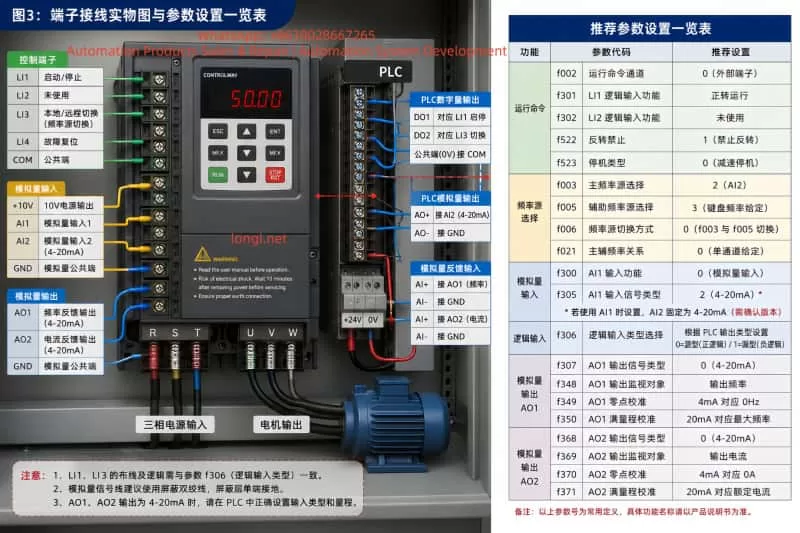
PLC-controlled Controlway IE series VFD wiring diagram for a dust extraction fan, showing AI2 4–20mA speed reference, LI1 start/stop command, LI3 local/remote frequency source switching, AO1 frequency feedback, AO2 current feedback, and motor output connections.

2. Define the Control Architecture Before Editing Parameters

Before changing any VFD parameters, the complete control structure should be defined clearly.

For this application, the recommended arrangement is:

Run command source: external terminals.

Run/stop input: LI1.

Remote frequency reference: AI2, 4–20mA signal from PLC.

Local frequency reference: VFD keypad frequency setting.

Frequency reference selection input: LI3.

AO1 output: actual output frequency, 4–20mA.

AO2 output: actual output current, 4–20mA.

The operating logic should be as follows:

In remote mode, the PLC sends a 4–20mA signal to AI2. The VFD converts this analog signal into the target operating frequency.

In local mode, the VFD ignores the remote frequency reference and follows the frequency manually entered through the keypad.

LI1 remains responsible for start and stop control in both local and remote frequency modes.

A critical distinction must be made between run-command source switching and frequency-reference source switching.

Run-command source switching determines whether the VFD start/stop command comes from the keypad, external terminals, or communication.

Frequency-reference source switching determines whether the speed command comes from AI2, AI1, keypad setting, communication, multi-speed inputs, or another source.

In many dust extraction fan projects, only the frequency reference needs to change between local and remote modes. The run/stop command remains controlled through LI1 or the PLC. In that case, the VFD must remain in external terminal run-command mode. Only the frequency source should switch between AI2 and keypad reference.

If the VFD is switched completely to keypad local mode, LI1 start/stop control may no longer function as intended. This is a frequent cause of commissioning confusion.

Control cabinet wiring and parameter setup example for a Controlway IE series VFD, showing PLC digital and analog signal connections, AI2 4–20mA input, AO1 frequency feedback, AO2 motor current feedback, local/remote selector wiring, and recommended VFD parameter settings.

3. Run Command Configuration

The Controlway IE series normally uses parameter f002 to select the run command channel.

Typical selections are:

f002 = 0: External terminal run command.

f002 = 1: Keypad run command.

f002 = 2: Serial communication run command.

For this application, the recommended setting is:

f002 = 0

This ensures that the fan is always started and stopped through external terminal logic.

LI1 should be configured as a forward run command.

When LI1 is active, the VFD runs the fan.

When LI1 is inactive, the VFD stops the fan.

For a standard one-direction dust extraction fan, LI1 is normally assigned to forward run only. Reverse operation is generally unnecessary and may create process problems, reverse airflow, belt stress, abnormal duct pressure, or unexpected dust movement.

A recommended arrangement is:

LI1: Forward run command.

LI2: Unused, fault reset, or reserved.

Reverse operation: Disabled.

The stop mode should also be selected according to the fan inertia and process requirements. For most dust extraction fans, deceleration stop is preferred because it provides a controlled stop. Free-run stop may cause a large fan to coast for a long period, affecting process interlocks and safety sequencing.

4. AI2 as the PLC 4–20mA Remote Frequency Reference

In remote mode, the PLC analog output should be wired to AI2.

The standard scaling principle is:

4mA = minimum frequency.

20mA = maximum frequency.

Intermediate current values correspond proportionally to intermediate frequencies.

For example, if the fan maximum frequency is 50Hz:

4mA = 0Hz or the minimum allowed operating frequency.

12mA = 25Hz.

20mA = 50Hz.

In many fan applications, the lower limit should not be set to 0Hz. Fans may suffer from poor cooling, unstable airflow, resonance, or insufficient dust extraction at very low speed.

For example:

4mA = 20Hz.

20mA = 50Hz.

Under this configuration, the fan runs at 20Hz when the PLC output is 4mA and reaches 50Hz at 20mA.

The minimum frequency should be determined according to fan curve, motor cooling, duct resistance, process airflow demand, and mechanical vibration conditions.

The Controlway IE series allows separate main and auxiliary frequency references. The recommended configuration is:

f003 = AI2.

f005 = Keypad frequency setting.

f006 = Frequency reference switching mode between f003 and f005.

f021 = Single-channel frequency reference structure.

With this arrangement:

Main frequency reference: AI2, used for remote PLC control.

Auxiliary frequency reference: keypad setting, used for local manual adjustment.

LI3 is then used to switch between the two frequency reference sources.

5. LI3 as the Local/Remote Frequency Reference Selector

LI3 should be assigned to the frequency-reference switching function.

It should not be assigned as a normal run command, stop command, multi-speed input, reset input, or other unrelated function.

A typical operating definition can be:

LI3 OFF: Remote mode, frequency reference from AI2.

LI3 ON: Local mode, frequency reference from keypad.

The opposite logic can also be used:

LI3 ON: Remote mode.

LI3 OFF: Local mode.

Either method is acceptable, but the electrical design, PLC program, switch label, operation manual, and VFD parameter logic must all match exactly.

A common site problem occurs when the selector switch is labeled “REMOTE,” but the actual LI3 state causes the VFD to use keypad frequency. Operators then assume that the PLC system has failed even though the VFD is simply using the wrong reference source.

The panel door should clearly identify the operating condition, for example:

REMOTE: PLC AI2 4–20mA frequency reference.

LOCAL: VFD keypad frequency reference.

RUN/STOP: Controlled by LI1.

The logic input type must also match the PLC output type.

The Controlway IE series supports source logic and sink logic.

For PNP transistor outputs, source logic is normally used.

For NPN transistor outputs, sink logic is normally used.

For relay dry-contact outputs, the actual control supply connection and COM/0V wiring must be checked carefully.

An incorrect source/sink logic setting can cause LI1 or LI3 to operate in reverse, remain permanently active, or fail to respond.

6. AI2 4–20mA Wiring and Signal Considerations

The PLC analog output should generally be connected as follows:

PLC AO+ to VFD AI2.

PLC AO− to VFD analog common or signal COM.

Use shielded twisted-pair cable for the analog signal.

Ground the shield at one end only, normally at the control cabinet side.

Do not route analog signal cables in parallel with motor output cables for long distances.

Keep analog signal cables separate from U, V, W motor cables.

Where crossing is unavoidable, cross at approximately 90 degrees.

A 4–20mA signal is generally more suitable than a 0–10V signal in industrial fan systems, especially where cable runs are long and electromagnetic interference is present.

Advantages include:

Better immunity to electrical noise.

Less influence from cable voltage drop.

More reliable transmission over longer distances.

Ability to detect some open-circuit or signal-failure conditions.

If the PLC output circuit opens or the signal cable is damaged, the analog value may drop below 4mA. Depending on process requirements, the VFD or PLC should include low-signal detection, minimum speed protection, fault alarms, or interlock logic to prevent the fan from operating at an unsuitable low speed.

It is also important to confirm that the actual VFD hardware and firmware version supports AI2 current input. Older manuals or earlier VFD versions may describe AI2 differently. Before commissioning, verify the VFD model, terminal board type, firmware version, and applicable manual revision.

7. AO1 Output Frequency Feedback Configuration

AO1 is used to provide actual VFD output frequency feedback to the PLC.

Recommended configuration:

AO1 signal type: 4–20mA.

AO1 monitored value: Actual output frequency.

4mA = 0Hz.

20mA = Maximum operating frequency.

For a 50Hz fan system:

0Hz = 4mA.

25Hz = 12mA.

50Hz = 20mA.

AO1 normally requires two separate settings:

First, the electrical output type must be set to current output.

Second, the internal monitored variable must be set to output frequency.

These two settings do not conflict. One defines the electrical format of the output signal, while the other defines the process value being transmitted.

For example:

AO1 output type = 4–20mA current output.

AO1 monitored value = output frequency.

The PLC should then scale the received signal correctly. If 4–20mA corresponds to 0–50Hz, the PLC engineering conversion should be:

Actual Frequency = (Measured Current − 4mA) / 16mA × 50Hz.

Incorrect PLC scaling can make the display value incorrect even when the VFD output is functioning properly.

8. AO2 Output Current Feedback Configuration

AO2 is used to provide the actual motor output current to the PLC.

This signal can be used for:

Motor load monitoring.

Fan blockage detection.

Belt slip indication.

Fan impeller fouling analysis.

Filter blockage trend monitoring.

Overload warning.

Maintenance planning.

Recommended configuration:

AO2 signal type: 4–20mA.

AO2 monitored value: Actual output current.

4mA = 0A.

20mA = VFD rated output current or selected monitoring full-scale current.

For example, if the VFD rated output current is 38A:

4mA = 0A.

20mA = 38A.

The PLC engineering conversion would be:

Actual Current = (Measured Current − 4mA) / 16mA × 38A.

The selected full-scale current must be consistent in three locations:

VFD AO2 scaling.

PLC analog input scaling.

HMI display and alarm thresholds.

If these values are inconsistent, the PLC may show incorrect motor current, false overload alarms, or an inaccurate loading trend.

9. Recommended Parameter Logic Summary

Run command channel:

f002 = External terminal control.

Main frequency reference:

f003 = AI2.

Auxiliary frequency reference:

f005 = Keypad frequency setting.

Frequency source switching:

f006 = Switch between f003 and f005.

Frequency reference structure:

f021 = Single-channel reference.

LI1:

Configure as Forward Run.

LI3:

Configure as Frequency Reference Source Switching.

Logic input type:

Configure according to PLC PNP/NPN output type and actual wiring.

AO1:

Set as current output.

Set monitored value as output frequency.

Set output range as 4–20mA.

AO2:

Set as current output.

Set monitored value as output current.

Set output range as 4–20mA.

Motor and fan protection settings:

Set maximum frequency according to fan design limits.

Set upper frequency limit according to process requirements.

Set lower frequency limit according to minimum stable fan operating speed.

Set acceleration time according to fan inertia.

Set deceleration time according to fan inertia and required stop behavior.

Disable reverse operation unless reverse rotation is specifically required.

Select deceleration stop unless free-run stop is required by the process.

10. Recommended Commissioning Sequence

Do not place the complete PLC control system into automatic operation immediately. Commission the system in stages.

Step 1: Disconnect the PLC analog output or force the PLC output to 4mA.

Step 2: Confirm motor nameplate data, maximum frequency, acceleration time, deceleration time, and rotation direction.

Step 3: Confirm that LI1 starts and stops the fan correctly.

Step 4: Switch LI3 to local mode and verify that keypad frequency setting controls the fan speed.

Step 5: Switch LI3 to remote mode and verify that AI2 receives the PLC 4–20mA signal correctly.

Step 6: Output 4mA, 8mA, 12mA, 16mA, and 20mA from the PLC and confirm that VFD frequency changes linearly.

Step 7: Verify that AO1 feedback matches the actual VFD output frequency.

Step 8: Verify that AO2 feedback matches the VFD current display and a clamp meter reading.

Step 9: Verify PLC display values, alarm thresholds, trend curves, remote/local status, and interlock logic.

Step 10: Run the dust extraction system under actual process load and monitor airflow, duct pressure, fan vibration, motor current, filter differential pressure, and operating stability.

11. Conclusion

The most important point in dust extraction fan VFD retrofit work is not a single parameter value. It is the consistency of the entire control architecture.

AI2 provides the PLC remote 4–20mA frequency reference.

The keypad provides the local frequency reference.

LI1 controls fan start and stop.

LI3 switches between local and remote frequency references.

AO1 sends actual frequency feedback to the PLC.

AO2 sends actual motor current feedback to the PLC.

When the frequency source, run command source, digital inputs, analog inputs, analog outputs, PLC scaling, and operator switch labeling are all coordinated correctly, the system becomes stable, maintainable, and easy to troubleshoot.

Posted on

GOOBELL G500 Inverter ERR29 Fault Mechanism and “Power-On Immediate Lockout (No Menu Access)” Case Study Analysis


1. Introduction: Why ERR29 Is Not Just a “Communication Fault Code”

In industrial inverter maintenance, ERR29 is often superficially categorized as a “communication fault.” However, in real-world GOOBELL G500 applications, this fault frequently represents a system-level control failure, involving:

  • Control source configuration logic
  • Communication state machine failure
  • HMI (keypad) UI access locking mechanism
  • Internal low-voltage control board instability

A typical field scenario shows the following behavior:

  • ERR29 appears immediately after power-on
  • No RUN command is required to trigger the fault
  • Fault persists even after disconnecting RS485/PLC wiring
  • Menu/parameter access is completely blocked
  • STOP/RESET cannot restore access

This indicates that the issue is no longer a simple communication wiring problem, but a control architecture-level fault state.


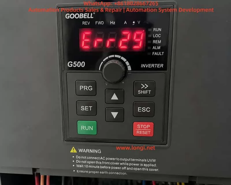
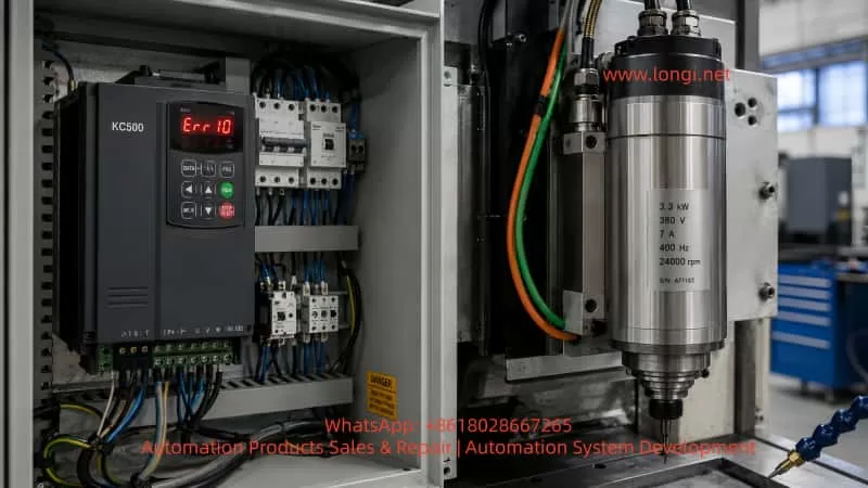
Close-up view of a GOOBELL G500 industrial frequency inverter control panel displaying an ERR29 fault code, with keypad buttons including RUN, STOP/RESET, PRG, and navigation keys, indicating a communication-related fault state on power-up.

2. Overview of GOOBELL G500 Control Architecture

To understand ERR29 correctly, the internal structure must be considered.

2.1 Power Circuit

  • Three-phase rectifier stage
  • DC bus (approx. 560–600V)
  • IGBT inverter module

2.2 Control System (Core Layer)

  • Main MCU (control logic processor)
  • PWM generation module
  • Protection detection circuits (overcurrent, overvoltage, undervoltage, overtemperature)

2.3 Human-Machine Interface (HMI)

  • Keypad panel (PRG / ENT / ESC / STOP)
  • Internal communication bus between keypad and main board

2.4 External Control Interfaces

  • RS485 Modbus communication
  • DI/DO terminal control
  • PLC remote operation signals

3. Actual Meaning of ERR29 in G500 Systems

In GOOBELL G500-type platforms, ERR29 is generally defined as:

External communication loss or invalid communication control source

However, in engineering practice, the key point is:

❗ ERR29 is not only “communication failure”, but also a “control authority loss condition”

When the drive is configured as:

  • RUN command source = COMMUNICATION (PLC/RS485)
  • Frequency reference = communication-based
  • External control enabled

If the inverter detects:

  • No valid PLC RUN command
  • Communication not established
  • Incorrect station address or baud rate

It enters:

Communication Fault Protection State (COMM FAULT LOCK)


4. Key Abnormal Symptoms in This Case

This case exhibits three critical symptoms:

4.1 ERR29 appears immediately after power-on

This indicates:

  • Fault occurs during initialization phase
  • Communication system fails at startup stage

4.2 Fault remains even after communication disconnection

This confirms:

  • External communication wiring is not the root cause
  • Internal logic state remains locked

4.3 Menu/parameter access is completely unavailable

This is the most critical symptom:

The UI system is locked at the fault display level.


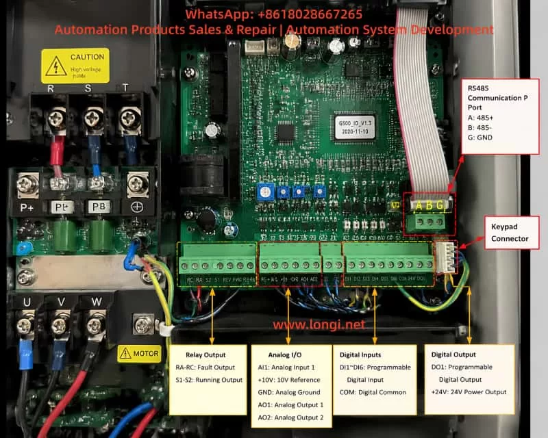
nternal view of an industrial inverter control board showing RS485 communication terminals, digital and analog I/O connectors, keypad interface cable, and main control PCB layout, illustrating signal routing and communication architecture used in VFD systems.

5. Fault Priority Lock Mechanism in G500

The GOOBELL G500 inverter uses a fault priority display system:

When communication control mode is active and communication is lost → the system enters a fault latch mode.

Characteristics:

  • Fault screen is permanently displayed (ERR29)
  • Keypad menu entry is blocked
  • RESET function is partially or fully ineffective
  • Control state machine is frozen awaiting communication recovery

6. Root Cause Analysis of This Case

Based on full isolation testing (communication removed, reset attempted, power cycling), the fault can be narrowed down to three categories:


6.1 Control Mode Latch State Not Cleared (High Probability)

If the drive is configured as:

  • Communication control mode enabled
  • PLC not responding at startup

The system enters a latched fault state where:

Even after communication is removed, the internal state remains in “waiting for communication” mode.

Result:

  • Menu access remains blocked
  • UI layer cannot be entered

6.2 Keypad-to-Mainboard Communication Failure (Medium Probability)

The keypad is not independent; it communicates with the main control board.

Possible issues:

  • Internal communication bus failure
  • Loose keypad cable connection
  • Keypad IC malfunction

Symptoms:

  • Display is normal
  • Keys are unresponsive or partially responsive
  • Menu cannot be accessed

6.3 Low-Voltage Control Power Instability (Medium-Low Probability)

Control board requires stable low-voltage rails:

  • +5V logic supply
  • +15V driver supply

If +5V is unstable:

  • MCU cannot properly execute state transitions
  • UI logic becomes frozen
  • Fault state cannot be cleared

7. Why “Communication Disconnected but Still Faulty” Is Critical

In normal communication faults:

ActionExpected Result
Disconnect RS485Fault clears
Switch to local modeMenu accessible

However, in this case:

❗ ERR29 persists even after full isolation

This indicates:

  • External control dependency has been removed
  • Internal state machine remains locked

8. Field Diagnostic Procedure (Engineering Standard)

Step 1: Full isolation of external control

  • Disconnect RS485 (A/B/SG)
  • Remove PLC control wiring
  • Keep only main power input

Step 2: Forced reset attempt

  • Hold STOP/RESET ≥ 5 seconds
  • Repeat multiple times

Step 3: UI access verification

Check if menu can be accessed:

  • PRG
  • Parameter groups
  • Monitoring mode

Step 4: Keypad function test

Test all keys:

  • STOP/RESET
  • PRG/MENU
  • ENT/ESC
  • Arrow keys

Step 5: Control voltage measurement

Measure control board supply:

  • +5V (4.8–5.1V)
  • +15V
  • Ground stability

9. Fault Classification Model

Level 1: External communication issue

✔ Already excluded

Level 2: Control mode latch state

✔ Most likely cause

Level 3: Keypad/HMI communication fault

✔ Possible

Level 4: Main control board hardware fault

✔ Requires confirmation


10. Recommended Repair Strategy

Option 1: Fast recovery method

  • Disconnect communication wiring
  • Switch to local control mode
  • Perform forced reset

Applicable only if menu access is possible


Option 2: Module replacement test (recommended)

  • Replace keypad panel
  • Cross-test UI functionality

Option 3: Mainboard-level diagnosis

  • Check +5V logic supply
  • Verify MCU operation
  • Inspect EEPROM/state memory lock

11. Key Engineering Insights

This case highlights an important field principle:

ERR29 on GOOBELL G500 is not always a simple communication fault; when accompanied by “no menu access,” it often indicates an internal control-state lock condition rather than an external wiring issue.

Key takeaways:

  1. ERR29 is a system-level fault, not only communication-related
  2. “No menu access” is more critical than the fault code itself
  3. Disconnecting communication without recovery indicates internal logic lock
  4. Diagnosis must shift from external wiring to internal control state

12. Conclusion

The GOOBELL G500 ERR29 “power-on immediate lockout with no menu access” case represents a multi-layer control system failure involving:

  • Communication control configuration
  • Internal fault latch mechanism
  • UI access restriction logic
  • Possible keypad or control board communication failure

The resolution is not limited to parameter adjustment, but requires a structured approach:

  • Control source recovery
  • Fault latch clearing
  • UI communication restoration
  • Hardware validation when necessary
Posted on

BYD New Energy Vehicle Electric A/C Compressor Fault Diagnosis: Do Not Assume the Compressor Has Failed Just Because the Air Conditioner Is Not Cooling

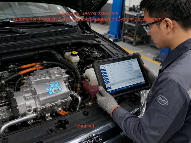
In new energy vehicle maintenance, complaints such as “the air conditioner is not cooling,” “the compressor makes no sound,” or “the diagnostic tester shows an A/C-related fault” are very common. In particular, when servicing BYD electric vehicles equipped with high-voltage electric air-conditioning compressors, many technicians still use the diagnostic habits developed from conventional gasoline vehicles: once the A/C does not work, they immediately suspect the compressor and may even recommend replacing the entire compressor assembly.

This approach is risky and often incorrect.

A new energy vehicle A/C compressor is not a conventional belt-driven mechanical compressor. It is a high-voltage electric device supplied by the traction battery, usually integrating an electric motor, inverter drive circuit, control electronics, protection circuits, and communication functions. Whether the compressor can run does not depend only on the compressor itself. It also depends on high-voltage system status, vehicle control permissions, battery management system conditions, refrigerant pressure, temperature sensors, A/C controller commands, CAN communication, and high-voltage interlock circuits.

Therefore, when diagnosing a BYD electric vehicle with suspected A/C compressor failure, the correct principle is:

Confirm whether the compressor has all required operating conditions before concluding that the compressor itself is defective.

A compressor should never be replaced simply because the A/C is not cooling, the compressor appears not to run, or a diagnostic screen shows an abnormal condition.

This article explains the structure, working logic, fault diagnosis process, key data parameters, and common misdiagnoses associated with BYD high-voltage electric A/C compressors. It is intended as a practical technical reference for electric vehicle service technicians, automotive repair workshops, and maintenance professionals.


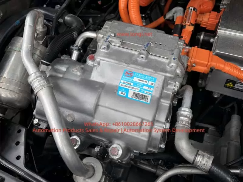
Close-up of a BYD high-voltage electric A/C compressor assembly installed in an electric vehicle, showing the aluminum compressor housing, R134a refrigerant pipes, orange high-voltage cables, and identification label.

1. Identifying the Component: This Is Not a Conventional Compressor

The nameplate on the component provides several important details:

  • Manufacturer: BYD Auto Industry Co., Ltd.
  • Description: Electric Compressor Assembly
  • Refrigerant: R134a
  • Rated operating voltage: approximately 408.8 V
  • Compressor model: HDE-8103020D
  • Compressor assembly identification code: ACE66D or similar, depending on the exact label marking

The most important markings are “Electric Compressor Assembly” and “408.8 V.”

These markings confirm that the component is part of the vehicle high-voltage thermal management system. Unlike a traditional engine-driven compressor, it is powered directly by the traction battery through the high-voltage system. The internal inverter converts high-voltage DC power into three-phase AC power to drive the compressor motor.

A high-voltage electric A/C compressor can generally be considered a combination of the following sections:

  1. Compressor mechanical body
  2. Three-phase permanent magnet motor
  3. Internal inverter drive module
  4. Electronic control board
  5. Rotor position or speed detection circuit
  6. High-voltage DC input section
  7. Low-voltage communication and control connector
  8. Internal temperature protection circuit
  9. Insulation monitoring-related structure
  10. Refrigerant compression and lubrication system

For this reason, the traditional gasoline vehicle inspection method of “checking whether the 12 V compressor clutch engages” does not apply to electric vehicles.

Most high-voltage electric compressors do not use conventional electromagnetic clutches. Their operation depends on whether the vehicle control system issues a speed command, whether high-voltage power is available, whether safety conditions are satisfied, and whether the compressor itself has internal electrical or mechanical faults.


2. Fundamental Differences Between EV and Conventional Vehicle A/C Systems

The operating logic of a conventional gasoline vehicle A/C system is relatively simple:

Engine running
→ Engine belt drives compressor
→ Electromagnetic clutch engages
→ Compressor circulates refrigerant
→ Evaporator produces cooling.

The logic of an electric vehicle A/C system is much more complex:

Traction battery high-voltage system powers on
→ BMS confirms battery status is acceptable
→ High-voltage contactors close
→ VCU confirms the vehicle is in an allowed operating condition
→ A/C controller receives a cooling request
→ System checks cabin temperature, ambient temperature, evaporator temperature, refrigerant pressure, and other conditions
→ A target compressor speed command is sent through CAN communication
→ Compressor verifies high-voltage supply, communication status, and internal conditions
→ Internal inverter drives the electric motor
→ Compressor circulates refrigerant and produces cooling.

This process shows that a compressor may fail to operate for many reasons other than compressor damage.

The main categories include:

  1. No A/C request or no compressor command
  2. High-voltage system not powered up correctly
  3. Compressor communication failure
  4. Refrigerant system conditions not satisfied
  5. Internal compressor electronic or mechanical fault
  6. Vehicle protection strategy disabling compressor operation

Therefore:

No cooling does not automatically mean the compressor has failed.
Compressor not running does not automatically mean the compressor assembly is defective.


Automotive technician using a diagnostic tablet to inspect a BYD electric vehicle high-voltage A/C compressor and thermal management system in a workshop.

3. Common Incorrect Judgments During Diagnosis

Several mistakes are frequently made when diagnosing high-voltage electric compressor faults.

3.1 No Audible Compressor Noise Means the Compressor Is Bad

This is not reliable.

Electric compressors can be very quiet, especially at low speed. In a noisy workshop environment, with cooling fans operating or with underbody insulation installed, it may be difficult to hear compressor operation from outside the vehicle.

The correct approach is to use a diagnostic tool and inspect live data such as:

  • A/C request status
  • Compressor enable status
  • Compressor target speed
  • Compressor actual speed
  • Compressor operating status
  • Compressor fault level
  • High-voltage bus voltage
  • Refrigerant pressure
  • Evaporator temperature
  • Compressor current or power consumption

If the target speed is commanded but actual speed remains zero, then the technician can begin to suspect the compressor, high-voltage supply, or communication circuit.


3.2 A/C Not Cooling Means Refrigerant Must Be Added or Compressor Must Be Replaced

This is another common mistake.

In an electric vehicle, low refrigerant charge, excessive refrigerant charge, refrigerant leakage, pressure sensor failure, electronic expansion valve malfunction, or poor condenser cooling can all prevent the compressor from operating.

For example:

  • If refrigerant pressure is too low, the system may assume leakage and disable the compressor.
  • If refrigerant pressure is too high, the system may enter overpressure protection.
  • If the evaporator temperature is too low, the controller may stop the compressor to prevent icing.
  • If the condenser fan is not working, high-side pressure may rise and trigger shutdown.
  • If the pressure sensor signal is unreliable, the controller may refuse to enable the compressor.

Therefore, adding refrigerant or replacing the compressor without checking pressure data and fault codes is not a professional diagnostic method.


3.3 Measuring High Voltage Directly at the Compressor Without Proper Procedure

This is dangerous.

The compressor label indicates an operating voltage around 408.8 V. The high-voltage input circuit may therefore carry several hundred volts DC. Improper disconnection of high-voltage connectors, careless measurement with an unsuitable multimeter, or failure to follow the correct high-voltage isolation procedure can result in electric shock, arcing, short circuits, or damage to the vehicle control system.

Before servicing a high-voltage compressor, technicians must follow the manufacturer-approved high-voltage shutdown procedure. This generally includes isolating high-voltage power, waiting for capacitor discharge, confirming absence of voltage, and using proper insulated safety equipment.


3.4 Diagnostic Tool Shows “Normal,” So the Compressor Must Be Good

This conclusion is also unreliable.

A diagnostic tool showing “normal” may only indicate that a control module has not reported a specific active fault or that communication with the module is currently available.

It does not necessarily prove that:

  • The compressor mechanical section is healthy.
  • The internal inverter is functioning correctly under load.
  • The compressor can run normally at commanded speed.
  • Refrigeration performance is normal.
  • The refrigerant circuit is operating correctly.

For example, a compressor may pass its static self-check but fail when it receives a high-speed command due to overcurrent, mechanical seizure, overheating, insulation issues, or internal inverter faults.

For this reason, fault codes, live data, dynamic operation, refrigerant pressure changes, and actual cooling performance must all be evaluated together.


4. Required Operating Conditions for a High-Voltage Electric Compressor

The most effective way to diagnose whether a high-voltage compressor should operate is not immediate disassembly. Instead, the technician should establish whether all operating conditions are present.

A typical high-voltage electric compressor requires the following conditions.

4.1 Vehicle High-Voltage System Must Be Active

The vehicle must successfully enter READY mode or complete its high-voltage power-up process.

If the traction battery contactors are not closed and the high-voltage bus is not established, the compressor cannot receive the required DC voltage and cannot operate.

Relevant checks include:

  • Can the vehicle enter READY mode normally?
  • Is there any traction system warning light?
  • Is there any insulation fault in the high-voltage system?
  • Are the high-voltage contactors closing correctly?
  • Does the BMS report any fault preventing high-voltage activation?
  • Is the service disconnect correctly installed?
  • Is the high-voltage interlock circuit intact?

4.2 The A/C Controller Must Issue a Cooling Request

Pressing the A/C button does not always mean the compressor must start immediately.

The controller may evaluate:

  • Ambient temperature
  • Cabin temperature
  • Requested set temperature
  • Evaporator temperature
  • Defrost requirements
  • Battery thermal management demand
  • Energy-saving strategy
  • Battery state of charge
  • Battery temperature
  • Vehicle operating mode
  • Communication status between A/C-related control units

For example, in cold ambient conditions, the compressor may not start immediately even when the A/C button is pressed. On the other hand, the compressor may run for battery thermal management even if the cabin cooling demand is low.


4.3 High-Voltage Supply Must Be Normal

The compressor requires stable high-voltage DC input.

The following items should be checked:

  • High-voltage bus voltage
  • Compressor high-voltage fuse
  • High-voltage connector condition
  • High-voltage cable damage
  • High-voltage power distribution output
  • High-voltage interlock circuit
  • Connector locking condition
  • Terminal corrosion, overheating, or looseness

It is important to understand that a high-voltage supply fault does not always mean complete loss of voltage. A loose connector, partially burnt terminal, or damaged cable may appear acceptable under no-load conditions. However, when compressor current rises during startup, voltage may collapse and trigger compressor protection.


4.4 CAN Communication Must Be Normal

In many electric vehicles, the compressor receives operating commands through CAN communication.

Relevant modules may include:

  • Vehicle Control Unit, VCU
  • Battery Management System, BMS
  • Air-conditioning controller
  • Thermal management controller
  • Battery thermal management controller
  • Electric compressor controller
  • DC-DC converter
  • PTC heater controller
  • Gateway module

If compressor CAN communication is abnormal, the following symptoms may occur:

  • A/C panel operates normally, but compressor does not start.
  • The display shows A/C enabled, but no cold air is produced.
  • Compressor communication fault codes are present.
  • Compressor target speed remains zero.
  • Diagnostic tester cannot access compressor live data.
  • Other high-voltage systems appear normal while thermal management functions fail.

4.5 Refrigerant System Pressure Must Be Within Normal Range

An electric compressor is not allowed to run under every condition simply because high voltage is present.

Many EVs use refrigerant pressure data to determine whether compressor operation is safe. If refrigerant pressure is too low, too high, unstable, or implausible, the controller may limit or stop compressor operation.

Typical issues include:

  • Refrigerant leakage causing low pressure
  • Incorrect refrigerant charge after repair
  • Condenser blockage or poor airflow
  • Electronic expansion valve sticking
  • Receiver-drier blockage
  • Pressure sensor drift
  • Damaged or crushed refrigerant pipes
  • Air or moisture contamination in the system
  • Incorrect compressor oil type

Electric compressors require refrigeration oil with suitable electrical insulation properties. Using incorrect oil, mixing conventional compressor oil, or contaminating the system with unsuitable service equipment can reduce insulation resistance and potentially cause electrical or internal compressor damage.


4.6 Compressor Internal Condition Must Be Normal

Only after all external operating conditions have been confirmed should the compressor itself become the primary suspect.

Internal compressor faults may include:

  • IGBT or MOSFET failure
  • DC bus capacitor failure
  • Drive board failure
  • Control chip failure
  • Motor winding short circuit, open circuit, or turn-to-turn fault
  • Rotor seizure
  • Scroll mechanism damage
  • Bearing damage
  • Internal temperature sensor fault
  • Rotor position sensor fault
  • Seal failure causing refrigerant or oil contamination
  • Insulation resistance failure
  • Water ingress or corrosion in electronic circuits

These faults are genuine compressor assembly faults.


5. Using Diagnostic Live Data to Determine Compressor Failure

The most valuable step in electric compressor diagnosis is reading complete live data before removing parts.

The following parameters should be checked whenever available:

ParameterNormal Diagnostic DirectionPossible Fault Direction
A/C request statusRequest activeA/C panel, controller, communication issue
Compressor enable statusAllowed to runProtection condition or system restriction
Compressor target speedTarget RPM presentController not commanding compressor
Compressor actual speedShould follow target RPMCompressor, power supply, communication, protection
Compressor statusNormal operationInternal fault or disabled status
High-voltage bus voltageWithin normal HV rangeBattery, contactor, fuse, wiring issue
Compressor currentShould change after startupNo startup, internal fault, supply problem
Refrigerant pressureWithin operating rangeRefrigerant, sensor, fan, blockage issue
Evaporator temperatureShould decrease during coolingCooling performance or sensor issue
Condenser fan statusShould operate when requiredFan, relay, controller issue
Battery temperatureWithin acceptable rangeThermal management or power limitation
Compressor fault codeNo active compressor faultUse code to guide diagnosis

The most important diagnostic logic is described below.

Condition A: Compressor Target Speed Is Zero

This means the vehicle is not requesting compressor operation.

In this case, do not suspect the compressor first. Check:

  • Is the A/C request active?
  • Does the A/C controller permit cooling?
  • Is ambient temperature appropriate?
  • Is cabin temperature above the set value?
  • Is refrigerant pressure normal?
  • Is evaporator temperature too low?
  • Is the BMS limiting power?
  • Is there a high-voltage or thermal management fault?
  • Is CAN communication normal?

Condition B: Compressor Target Speed Exists but Actual Speed Remains Zero

This condition is highly important.

It means the vehicle has commanded the compressor to operate, but the compressor has not successfully started.

The technician should focus on:

  • Compressor high-voltage supply
  • High-voltage fuse
  • High-voltage connector
  • High-voltage interlock circuit
  • Compressor CAN communication
  • Compressor internal fault codes
  • Compressor temperature
  • Compressor mechanical seizure
  • Compressor insulation status

If high voltage, CAN communication, control command, and refrigerant conditions are all normal, but the compressor still cannot establish actual speed, the probability of internal compressor failure becomes high.


Condition C: Compressor Speed Exists but Cooling Performance Is Poor

This situation does not automatically require compressor replacement.

It indicates that the compressor may be running, but the refrigeration system is not performing correctly.

Focus on:

  • Refrigerant charge level
  • Leakage
  • Condenser cooling efficiency
  • Cooling fan operation
  • Expansion valve condition
  • Refrigerant line blockage
  • Evaporator icing
  • Pressure sensor reliability
  • Reduced compressor displacement or compression efficiency

Condition D: Compressor Starts Briefly and Then Stops

This is a common symptom and is not always caused by compressor damage.

Possible causes include:

  • Excessive refrigerant pressure
  • Condenser fan failure
  • Refrigerant overcharge
  • Compressor internal overheating
  • High-voltage bus voltage fluctuation
  • High-voltage terminal contact resistance
  • Compressor overcurrent
  • Internal inverter protection
  • Insulation monitoring fault
  • Intermittent CAN communication loss
  • Battery system power limitation

The best approach is to record freeze-frame data and observe which parameter becomes abnormal immediately before shutdown.


6. Common BYD High-Voltage Compressor Fault Types

6.1 High-Voltage Fuse or Connector Fault

The compressor normally receives power through the high-voltage power distribution system. If the fuse is open, the connector is loose, terminals are burnt, or the cable is damaged, the compressor may not start.

Typical symptoms include:

  • Vehicle can enter READY mode.
  • Other high-voltage systems may work normally.
  • A/C compressor has no response.
  • High-voltage supply-related fault code may be present.
  • Compressor target speed exists, but actual speed remains zero.

Inspect high-voltage connectors carefully for:

  • Burn marks
  • Darkened terminals
  • Melted plastic
  • Loose terminals
  • Damaged seals
  • Connector not fully locked
  • Moisture ingress
  • Cable insulation wear

6.2 High-Voltage Interlock Circuit Fault

The high-voltage interlock circuit confirms that high-voltage components, service disconnects, and connectors are correctly connected.

For example, if the compressor high-voltage connector is not fully locked, the service disconnect is not installed correctly, or another high-voltage connector is loose, the vehicle may disable some or all high-voltage functions.

A high-voltage interlock fault may not always appear as a direct “compressor fault.” It may present as:

  • Vehicle unable to enter READY mode
  • High-voltage system not powering on
  • Reduced power mode
  • A/C not functioning
  • High-voltage warning lamp illuminated
  • Several high-voltage components reporting faults simultaneously

Therefore, technicians should inspect the complete high-voltage system rather than focusing only on the compressor.


6.3 Refrigerant Leakage or Pressure Sensor Inaccuracy

Sometimes the compressor does not start because the A/C controller considers refrigerant pressure abnormal.

Possible causes include:

  • Refrigerant leakage causing low pressure
  • Condenser or pipe leakage after impact
  • Incorrect vacuuming or charging procedure after repair
  • Loose pressure sensor connector
  • Pressure sensor internal drift
  • Refrigerant circuit blockage
  • Poor condenser heat dissipation causing high pressure

In these cases, the compressor may be completely healthy but will not receive permission to run.


6.4 Condenser Fan Failure

A condenser fan failure can cause poor heat dissipation and excessive high-side pressure.

Typical symptoms include:

  • Cold air is available initially.
  • Cooling becomes weak after several minutes.
  • Cooling is better while driving but poor when stationary.
  • Compressor cycles on and off repeatedly.
  • Refrigerant high-side pressure rises quickly.
  • Cooling fan does not run or runs at insufficient speed.

If the fan fault is ignored, repeated high-pressure operation can cause frequent compressor protection events and may eventually contribute to compressor overheating.


6.5 Internal Inverter Drive Module Failure

A high-voltage electric compressor contains its own inverter drive circuit. When internal power components fail, possible symptoms include:

  • Compressor cannot start.
  • Compressor faults immediately during startup.
  • High-voltage fuse opens.
  • Internal drive fault code is stored.
  • Overcurrent, short-circuit, or phase-current faults are reported.
  • Motor winding-related faults are reported.
  • Compressor starts briefly and shuts down.

These faults often require compressor replacement or specialist repair by a workshop with capability to test high-voltage electric drive components.


6.6 Mechanical Seizure or Internal Wear

Many electric compressors use scroll compression mechanisms. Long-term operation, contaminated refrigerant oil, insufficient refrigerant, foreign material, or poor lubrication may cause internal mechanical damage.

Typical symptoms include:

  • Excessive startup current
  • Abnormal metallic friction noise
  • Significant loss of cooling capacity
  • Abnormally high compressor temperature
  • Metal particles in refrigerant oil
  • Repeated compressor protection
  • Compressor speed feedback present but poor cooling performance

If internal mechanical damage is confirmed, replacing only the compressor may not be sufficient. The entire refrigerant circuit must be checked and cleaned. Otherwise, metal particles or contamination can damage the replacement compressor.


7. Standard Diagnostic Procedure for Confirming Compressor Failure

The following procedure can be applied to most high-voltage electric vehicle A/C compressor faults.

Step 1: Confirm the Actual Symptom

Clarify the customer complaint:

  • No cooling at all
  • Weak cooling
  • Intermittent cooling
  • Cooling while driving but not when stationary
  • A/C-related warning message
  • Vehicle unable to enter READY mode
  • High-voltage fault appears when A/C is switched on
  • Compressor starts and stops immediately
  • Abnormal compressor noise
  • Refrigerant or oil leakage around the compressor

Different symptoms require different diagnostic priorities.


Step 2: Scan All Vehicle Fault Codes

Do not scan only the A/C system.

At minimum, inspect fault codes from:

  • VCU
  • BMS
  • A/C controller
  • Thermal management controller
  • Compressor
  • High-voltage power distribution system
  • Gateway
  • DC-DC converter
  • Insulation monitoring system
  • Motor controller

Pay particular attention to:

  • High-voltage interlock faults
  • High-voltage activation faults
  • Compressor communication faults
  • Compressor internal faults
  • Pressure sensor faults
  • Temperature sensor faults
  • High-voltage insulation faults
  • CAN communication faults
  • Refrigerant pressure faults
  • Condenser fan faults

Fault codes must be evaluated together with freeze-frame data, live data, current fault status, and historical records. Clearing a fault code does not confirm that the root cause has been repaired.


Step 3: Confirm High-Voltage System Readiness

Verify:

  • Vehicle can enter READY mode.
  • Traction battery state of charge is sufficient.
  • High-voltage contactors close normally.
  • High-voltage bus voltage is normal.
  • No insulation fault exists.
  • No high-voltage interlock fault exists.
  • Service disconnect is correctly installed.
  • High-voltage wiring and connectors are intact.

If the vehicle cannot establish high-voltage power, diagnose the high-voltage system first instead of beginning with the compressor.


Step 4: Check Compressor Request, Target Speed, and Actual Speed

This is the key diagnostic step.

The logic can be summarized as follows:

No A/C request
→ Check control conditions.

A/C request present, but compressor not enabled
→ Check protection conditions, pressure, temperature, high voltage, and communication.

Target speed present, actual speed zero
→ Check compressor power supply, communication, and internal fault status.

Target speed and actual speed both present
→ Check refrigerant circulation, condenser cooling, expansion valve, and cooling efficiency.


Step 5: Check the Refrigerant System

Use suitable R134a A/C service equipment to inspect:

  • Static low-side and high-side pressure
  • Dynamic low-side and high-side pressure
  • Refrigerant charge quantity
  • Vacuum holding condition
  • Leakage
  • Condenser cooling efficiency
  • Cooling fan operation
  • Refrigerant pipe temperature difference
  • Expansion valve operation
  • Receiver-drier condition
  • Evaporator icing condition

Electric vehicle compressors are highly sensitive to oil type and system cleanliness. Avoid mixing refrigerant oils and avoid introducing contamination from conventional vehicle A/C service equipment.


Step 6: Evaluate the Compressor Assembly

Only after confirming the following conditions should the compressor itself be considered a primary fault source:

  • High-voltage supply is normal.
  • High-voltage interlock is normal.
  • CAN communication is normal.
  • A/C request is normal.
  • Controller is sending a target speed command.
  • Pressure and temperature conditions are normal.
  • Condenser fan is operating correctly.
  • Wiring and connectors are intact.
  • No other system is preventing compressor operation.
  • Compressor fault code indicates an internal failure.
  • Actual speed cannot be established or is unstable.

At this stage, the compressor internal failure probability is high.


8. Important Precautions Before Replacing the Compressor

If the compressor assembly is confirmed defective, replacement should not be treated as a simple remove-and-install operation.

8.1 Confirm Exact Part Compatibility

Verify:

  • Compressor part number
  • Voltage class
  • Refrigerant type
  • Connector type
  • Communication protocol
  • Pipe connection design
  • Mounting bracket configuration
  • Software compatibility
  • Vehicle platform
  • Compressor capacity and power rating

Two compressors may look similar and use similar mounting points but still be incompatible electrically or electronically.


8.2 Check for Refrigerant System Contamination

If the original compressor has suffered internal mechanical damage, inspect the refrigerant system for metal particles, dark oil, sludge, or severe contamination.

Depending on the condition, it may be necessary to:

  • Replace the receiver-drier
  • Flush the refrigerant pipes
  • Inspect the electronic expansion valve
  • Inspect the condenser
  • Replace components that cannot be reliably cleaned
  • Use approved refrigerant oil
  • Perform a proper vacuum procedure
  • Charge refrigerant according to the vehicle specification

Failure to clean a contaminated system can lead to rapid failure of the replacement compressor.


8.3 Perform Insulation and Functional Verification After Replacement

After replacement, do not only confirm that cold air is available.

Also verify:

  • High-voltage insulation condition
  • High-voltage connector locking
  • Absence of high-voltage fault codes
  • Compressor target and actual speed
  • Compressor current
  • Refrigerant pressure readings
  • Pipe temperature difference
  • Condenser fan operation
  • Battery thermal management function
  • Long-duration operating stability
  • Absence of abnormal noise, refrigerant leak, or repeated protection shutdown

The goal of high-voltage vehicle repair is not only to restore cooling performance, but also to confirm electrical safety, insulation integrity, and proper control logic.


9. Final Judgment: Is the Compressor in the Image Necessarily Faulty?

For a component identified as a BYD high-voltage electric A/C compressor assembly, the following technical conclusion is appropriate:

First, it is indeed a key high-voltage actuator in the vehicle thermal management and air-conditioning system.

Second, it can cause no-cooling symptoms if it has internal inverter failure, motor winding failure, mechanical seizure, insulation fault, or other internal damage.

Third, compressor appearance, nameplate information, an A/C complaint, or a single diagnostic screen are not enough to confirm compressor failure.

Fourth, if diagnostic data shows that the vehicle is commanding a compressor target speed, high-voltage supply is normal, CAN communication is normal, refrigerant pressure conditions are normal, condenser fan operation is normal, but actual compressor speed remains zero, or the compressor reports internal overcurrent, drive fault, winding fault, or insulation fault, then internal compressor failure becomes highly likely.

Fifth, if compressor target speed is zero, the problem is more likely related to control conditions, high-voltage activation, pressure sensor data, CAN communication, thermal management strategy, or vehicle protection logic rather than the compressor itself.

Therefore, the technically correct answer to the question “Is the A/C compressor defective because the air conditioner is not cooling?” is:

The compressor is an important suspected component, but it cannot be condemned without testing.
High-voltage power, A/C request, communication status, pressure and temperature data, compressor target speed, and actual speed must be checked before deciding whether to replace the compressor assembly.


10. Conclusion

High-voltage electric A/C compressor diagnosis in new energy vehicles is not simply an air-conditioning repair task. It is a combined diagnosis involving the high-voltage system, electronic control system, communication network, and refrigerant circuit.

For BYD electric vehicles using high-voltage electric compressors, technicians must move away from traditional gasoline vehicle diagnostic habits. Do not add refrigerant immediately when cooling is poor. Do not replace the compressor simply because no compressor noise is heard. Do not disconnect high-voltage connectors without following proper isolation procedures.

A correct diagnostic sequence should be:

Read fault codes
→ Confirm high-voltage system status
→ Check A/C request
→ Compare compressor target speed and actual speed
→ Verify high-voltage power supply and CAN communication
→ Check refrigerant pressure and condenser cooling conditions
→ Finally determine whether the compressor itself has failed.

Following this process helps avoid unnecessary replacement of expensive components, reduces repair costs, improves diagnostic accuracy, and ensures safe servicing of high-voltage electric vehicle systems.

Posted on

Intermittent Phase Loss in VFD Systems: A Real-World Case Study on AT900 Series Drive Start Failure and Resolution

1. Introduction

In industrial motor drive applications, especially in textile, sewing, packaging, and light mechanical equipment, one of the most frequently misdiagnosed problems is “motor unable to self-start under inverter control but able to run once externally assisted”.

This case study is based on a real field troubleshooting scenario involving an AT900 series vector VFD (0.75–11kW class) controlling a sewing machine drive system. The system initially presented unstable starting behavior, requiring mechanical assistance via clutch engagement. After systematic diagnosis, the root cause was identified as an intermittent phase loss caused by an aging main contactor/fuse assembly.

The final resolution restored stable and smooth operation without vibration, confirming correct VFD behavior and motor integrity.


2. System Overview

The drive system consists of:

  • AT900 series high-performance vector inverter (SVC control mode)
  • Three-phase induction motor (~0.7–2.2kW class typical for sewing machines)
  • Mechanical clutch coupling system
  • Old-generation main contactor and fuse assembly
  • Direct inverter-to-motor wiring (no encoder feedback)

According to AT900 technical specifications, the inverter supports:

  • Sensorless vector control (SVC)
  • V/F control modes
  • Adjustable torque boost (0.1%–30%)
  • Starting torque up to 150% depending on configuration

Industrial maintenance technician diagnosing a sewing machine drive system powered by a variable frequency drive, inspecting wiring connections and using measurement tools inside an electrical control panel during troubleshooting.

3. Initial Failure Symptoms

The operator reported:

  1. Motor does not start autonomously under RUN command
  2. If the clutch is manually engaged (mechanical rotation applied), motor runs normally
  3. When RUN is triggered, frequency rises smoothly from 0Hz → 15Hz
  4. Motor never reaches stable self-start torque region
  5. Changing torque boost (P04.01) and overload gain (P10.01) had no effect

Additionally:

  • Motor could not self-start even when unloaded (belt removed test)
  • Behavior was consistent but intermittent in severity

This symptom pattern strongly indicated a starting torque deficiency or phase imbalance condition, not a parameter tuning issue.


4. Critical Diagnostic Breakthrough

The decisive observation was:

Motor starts normally when externally rotated, but fails to self-start.

This is a classic signature of:

  • Phase loss (single-phase operation under load)
  • Intermittent contactor failure
  • High contact resistance in one phase path
  • Unequal phase voltage delivery to motor terminals

Such conditions reduce rotating magnetic field symmetry, preventing torque generation at zero speed.


5. Electrical Measurements

After correction and stabilization, measured values were:

  • Motor phase resistances:
    • 19.7 Ω / 18.9 Ω / 19.7 Ω
  • Cable/inverter-to-motor resistance:
    • ~0.2 Ω (excellent continuity)

Interpretation:

ParameterStatus
Motor winding symmetryAcceptable (±4% deviation)
Cable integrityExcellent
Inverter outputNormal
Historical issueExternal phase interruption

The winding values confirmed the motor itself was healthy. Therefore, the fault had to be upstream of the motor terminals.


Technician repairing and replacing a faulty electrical contactor in a VFD-controlled sewing machine motor system, showing the drive operating smoothly after correction in an industrial workshop setting.

6. Root Cause Analysis

The final confirmed root cause was:

Intermittent missing phase caused by an aged main contactor / fuse assembly

Mechanism of failure:

Old contactor systems typically suffer from:

  • Oxidized silver alloy contacts
  • Arc erosion at switching points
  • Thermal expansion loosening internal pressure
  • Intermittent phase dropout under load
  • High resistance phase causing voltage imbalance

Under VFD operation, this leads to:

  1. One phase voltage drop or distortion
  2. Weak rotating magnetic field
  3. Zero-speed torque collapse
  4. Failure to self-start
  5. Motor only operates when externally “forced into motion”

Once rotating, back-EMF stabilizes the field, allowing operation.


7. Why Parameter Changes Failed

Attempts were made to adjust:

  • Torque boost (P04.01)
  • Motor overload gain (P10.01)

However, these parameters only affect:

  • Low-frequency voltage compensation
  • Thermal protection scaling
  • SVC torque estimation correction

They cannot compensate for missing or unstable phase supply.

From AT900 control logic:

  • Torque generation depends on balanced three-phase voltage vector synthesis
  • Phase imbalance cannot be corrected by software gain alone

Thus, all tuning attempts were logically ineffective.


8. Final Corrective Action

The site implemented:

Hardware replacement

  • Replacement of old contactor/fuse assembly
  • Restoration of stable three-phase supply path

System verification

  • Balanced phase continuity confirmed
  • Direct inverter-to-motor wiring validated
  • No external switching elements remaining

9. Final Performance Result

After correction:

  • Motor starts reliably every time
  • Smooth acceleration curve
  • No vibration during low-speed operation
  • Correct rotational direction
  • Stable sewing machine mechanical operation

This confirms:

✔ VFD control system is healthy
✔ Motor insulation and windings are healthy
✔ Mechanical system is properly aligned
✔ Fault was purely upstream electrical distribution


10. Engineering Lessons Learned

10.1 Phase integrity is more important than parameter tuning

In VFD systems, hardware phase continuity is foundational. Any imbalance directly affects:

  • Torque production
  • Startup stability
  • Current waveform symmetry

10.2 “Push-start symptom” is a diagnostic signal

If a motor:

  • Fails at zero speed
  • Runs normally after external rotation

Then likely causes are:

  • Phase loss
  • Voltage imbalance
  • Incorrect wiring topology
  • Weak starting flux condition

10.3 Do not modify VFD parameters before electrical verification

This case confirms a common diagnostic mistake:

Adjusting torque, frequency, and protection parameters without confirming power integrity leads to false troubleshooting cycles.


10.4 Mechanical clutch systems can mask electrical faults

The clutch in this system:

  • Masked inability to self-start
  • Allowed motor to bypass zero-speed torque requirement
  • Created illusion of “weak torque setting”

11. AT900 Series Control Insight

This inverter family uses:

  • Sensorless vector control (SVC)
  • Voltage vector synthesis based on phase stability
  • Torque estimation dependent on current feedback consistency

Therefore:

  • Any upstream phase distortion directly disrupts vector calculation
  • Protection systems may not immediately trigger fault codes
  • Symptoms appear as “soft failure” rather than hard trip

12. Conclusion

This case demonstrates a classic but often misdiagnosed industrial fault:

A motor that cannot self-start under VFD control is not always a tuning problem — it is frequently a power integrity problem upstream of the drive.

The final resolution required:

  • Rejecting parameter-centric diagnosis
  • Performing hardware continuity validation
  • Identifying intermittent phase loss in aging switching components
  • Replacing degraded contactor/fuse assembly

Once corrected, the system returned to full performance with:

  • Stable torque at low frequency
  • Smooth acceleration
  • Correct direction control
  • Fully reliable restart behavior

13. Practical Recommendation for Engineers

When encountering similar cases:

  1. Do NOT increase torque boost blindly
  2. Always verify:
    • Phase-to-phase voltage balance
    • Contactors / fuses / connectors condition
    • Continuity under load, not only static measurement
  3. Test motor behavior:
    • With load disconnected
    • With external rotation assistance
  4. Only then proceed to VFD parameter tuning
Posted on

Parameter Setup and Troubleshooting for Driving a 400 Hz High-Speed Spindle Motor with a KC500 Inverter

High-speed spindle motors are widely used in CNC routers, woodworking machines, engraving machines, small machining centers, grinding machines, and other high-speed cutting equipment. These motors are very different from ordinary 50 Hz industrial motors. A typical high-speed spindle motor may have nameplate data such as 380 V three-phase input, 400 Hz rated frequency, 24,000 rpm rated speed, and a power rating from 1.5 kW to 5.5 kW or higher.

Because the rated frequency is much higher than the normal mains frequency, this type of spindle motor must be driven by a variable frequency drive. It cannot be connected directly to a 380 V three-phase power supply. When a general-purpose inverter such as the KC500 series is used to drive a 400 Hz spindle motor, correct parameter setting is essential. Incorrect parameters may cause the spindle to stop at 50 Hz, fail to accelerate above 100 Hz, only shake without rotating, or trigger overload faults such as Err10.

This article analyzes a typical case: a KC500 inverter was used to drive a 3.3 kW, 380 V, 7 A, 400 Hz, 24,000 rpm high-speed spindle motor. The customer reported that the device was limited to 50 Hz, then limited to 100 Hz, and the spindle only tried to turn but could not start properly. Later, the inverter displayed an Err10 fault. This is a typical example of incorrect inverter selection, incorrect parameter group understanding, insufficient current margin, and unsuitable commissioning procedure.

KC500 inverter displaying Err10 fault connected to a 400 Hz high-speed spindle motor in an industrial CNC control cabinet.

1. Difference Between a 400 Hz Spindle Motor and a Standard 50 Hz Motor

A standard three-phase induction motor usually has a rated frequency of 50 Hz or 60 Hz. Its rated speed is normally around 1450 rpm, 2900 rpm, or similar values depending on pole number. A high-speed spindle motor is designed differently. It often uses a much higher rated frequency, such as 300 Hz, 400 Hz, 600 Hz, or even higher.

For a 400 Hz, 24,000 rpm spindle motor, the rated operating point is 400 Hz, not 50 Hz. This means the motor reaches its rated speed and rated output power only when the inverter output frequency is close to 400 Hz. If the inverter is only set to 50 Hz, the spindle runs at only about one-eighth of its rated speed. The output torque and power at that point are limited, and the motor may not be able to start under load.

This is a key point. Many technicians are used to ordinary industrial motors and assume that 50 Hz is the normal operating frequency. For a high-speed spindle motor, this assumption is wrong. If the maximum frequency, upper frequency limit, or frequency source is not set correctly, the inverter may remain limited at 50 Hz. The spindle may then only vibrate, hum, or attempt to rotate without actually accelerating.

A 400 Hz spindle motor also has weaker low-frequency performance than many standard motors. It is normally intended to run at medium to high frequencies. At very low frequency, especially under load, the available starting torque may be insufficient. Therefore, during commissioning, it is often better to test carefully at around 100 Hz with a long acceleration time, rather than forcing the motor to run at 50 Hz under load.

Wiring and parameter setup diagram for a KC500 inverter driving a 380V 400Hz high-speed spindle motor with P0, P1, and P2 parameter guidance.

2. Inverter Selection: Do Not Only Look at the Light-Duty kW Rating

In this case, the inverter used by the customer was marked as KC500-4T-0022G/0040P. This model indicates approximately 2.2 kW heavy-duty rating and 4.0 kW light-duty rating. The output current was marked as 6 A / 10 A.

At first glance, some users may think that because the inverter has a 4.0 kW light-duty rating, it should be able to drive a 3.3 kW spindle motor. This is a common mistake.

For a spindle motor, it is not enough to select the inverter only by the light-duty kW rating. The key is output current and overload capacity under actual load. A high-speed spindle may require strong current during starting, acceleration, cutting, grinding, or when bearing friction is high. For this type of load, the heavy-duty rating is more relevant than the light-duty rating.

The motor in this case is rated at 3.3 kW and 7 A. The inverter heavy-duty output current is only about 6 A. This is already lower than the motor rated current. If the acceleration time is short, the mechanical load is high, the spindle bearing is tight, or the parameters are not correct, the inverter can easily enter overload protection and display Err10.

For a 3.3 kW, 7 A, 400 Hz spindle motor, a more suitable inverter would be KC500-4T3.7G/5.5P or a larger model. A larger inverter provides more current margin, better acceleration capability, and a lower probability of overload faults.

3. Meaning of Err10 on the KC500 Inverter

Err10 generally indicates inverter overload. It is not simply a wiring alarm. It means the inverter is being required to deliver more load current or load capacity than it can safely provide for a certain period.

Common causes include:

The mechanical load is too heavy. The spindle bearing may be damaged, the shaft may be stuck, the belt may be too tight, the coupling may be misaligned, or a cutting tool/load may still be attached during testing.

The motor parameters are incorrect. If rated power, voltage, current, frequency, and speed are not entered correctly, the inverter’s motor model and protection logic will not match the real motor.

The inverter is undersized. In this case, the spindle motor rated current is 7 A, while the inverter heavy-duty current is only around 6 A.

The acceleration time is too short. Accelerating a high-speed spindle from zero to several hundred hertz requires time. If the acceleration ramp is too aggressive, the inverter current rises quickly and may trigger overload or overcurrent.

The control mode or related parameters are unsuitable. For first commissioning, V/F control is usually safer and easier than changing vector speed loop parameters. Incorrectly changing P2 group parameters may cause poor startup behavior or unstable motor control.

Technician troubleshooting a KC500 inverter Err10 overload fault while measuring current on a 3.3 kW 400 Hz spindle motor system.

4. Do Not Confuse P0, P1, P2, and P3 Parameter Groups

One important issue in this case was that the customer wrote down parameters such as P2-00 = 400 Hz, P2-01 = 20 s, and P2-02 = 20 s. This is incorrect. P2 group is not the correct place to set maximum frequency, acceleration time, or deceleration time.

On many KC500 applications, the parameter groups have different functions:

P0 group is the basic function group. It includes control mode, run command source, frequency source, keypad frequency setting, maximum frequency, upper frequency limit, lower frequency limit, acceleration time, deceleration time, and other basic operating parameters. If the spindle cannot exceed 50 Hz, the first group to check is usually P0.

P1 group is the motor parameter group. It should contain motor nameplate data such as rated power, rated voltage, rated current, rated frequency, and rated speed. These values must be set according to the motor nameplate.

P2 group is normally related to vector control and speed loop parameters. It is not the correct group for basic spindle frequency setting. During basic V/F commissioning, users should not randomly modify P2 parameters. If P2 parameters have already been changed incorrectly, they should be restored to default values before further testing.

P3 group is usually related to V/F control characteristics, including V/F curve and torque boost. For high-speed spindle applications, a linear V/F curve is usually used first. Low-frequency torque boost can be applied carefully, but excessive boost may cause high current and overheating.

Confusing these parameter groups is one of the most common reasons why the spindle cannot start correctly.

5. Why the Inverter May Be Limited to 50 Hz

If a 400 Hz spindle motor is limited to 50 Hz, the problem is usually not the motor itself. It is normally caused by inverter parameter limits or frequency source configuration.

Common causes include:

The maximum frequency is still set to 50 Hz.

The upper frequency limit is still set to 50 Hz.

The keypad frequency setting is only 50 Hz.

The frequency source is not the keypad but an external analog signal, terminal input, or communication command.

The analog input scaling is set so that maximum input only corresponds to 50 Hz.

The run command source and frequency source are bound to another channel.

For a 400 Hz spindle motor, both the maximum frequency and the upper frequency limit must allow 400 Hz operation. It is not enough to change only one parameter. If maximum frequency is set to 400 Hz but the upper limit remains at 50 Hz, the actual output will still be limited. If the frequency source is not the keypad, the keypad setting may also be ignored.

During first commissioning, the simplest method is to use keypad start/stop and keypad digital frequency setting. This removes confusion from external terminals, potentiometers, PLC communication, or analog input scaling.

6. Recommended Basic Parameter Logic for a 400 Hz Spindle

For a 3.3 kW, 380 V, 7 A, 400 Hz, 24,000 rpm spindle motor, the basic setup logic should be as follows.

Use V/F control for first testing. Use keypad command for run/stop. Use keypad digital setting as the frequency source. Set maximum frequency to 400 Hz. Set the upper frequency limit to 400 Hz. Set the lower frequency limit to 0 Hz or a suitable safe value. Set acceleration and deceleration times to a relatively long value at first, such as 20 to 30 seconds.

Motor nameplate data must be entered correctly:

Rated power: 3.3 kW
Rated voltage: 380 V
Rated current: 7 A
Rated frequency: 400 Hz
Rated speed: 24,000 rpm

For the V/F curve, use a linear V/F curve first. A small amount of torque boost may be used to improve low-frequency starting, for example 3% to 5%. However, torque boost should not be increased blindly. Too much boost can cause excessive low-frequency current and overheating.

The most important warning is this: do not set P2-00 as 400 Hz, and do not set P2-01 or P2-02 as acceleration/deceleration time unless the exact function of those parameters is confirmed. For this basic spindle setup, P2 should generally be left at default values.

7. Why the Spindle Only Tries to Turn but Cannot Start

When the spindle only shakes or attempts to turn but cannot accelerate, several causes are possible.

First, the spindle may have mechanical resistance. Before electrical testing, the spindle should be rotated by hand with power off. It should rotate smoothly. If it feels tight, stuck, noisy, or rough, the mechanical problem must be solved first.

Second, the motor winding may have a problem. The resistance between U-V, V-W, and W-U should be balanced. Insulation from winding to ground should be good. A winding fault can cause abnormal current, vibration, or inverter trip.

Third, the inverter may be too small. In this case, the inverter heavy-duty rating is lower than the motor rated current. Even if the motor can rotate without load, it may fail under real conditions.

Fourth, the frequency and V/F settings may be wrong. If the inverter is trying to start a 400 Hz spindle at an unsuitable low frequency with insufficient voltage compensation, the motor may not develop enough torque.

Fifth, acceleration may be too aggressive. A high-speed spindle should not be forced to accelerate too quickly during the first test.

8. Correct Commissioning Procedure

A high-speed spindle motor should not be tested by immediately running to 400 Hz. The commissioning process should be gradual and controlled.

First, check the wiring. Three-phase input power should be connected to R/S/T. The spindle motor should be connected to U/V/W. The motor ground wire must be connected to PE/earth. No capacitor, contactor, power factor correction capacitor, or surge absorber should be installed between the inverter output and the motor.

Second, check the mechanical condition. The spindle should rotate freely by hand when power is off. If possible, remove the tool and test without load first.

Third, simplify the control system. Use keypad operation first. Do not use external terminals, analog input, or communication control until the motor runs correctly.

Fourth, set the correct basic parameters. Set P0 and P1 correctly. Do not randomly change P2. Use V/F control and a long acceleration time.

Fifth, test step by step. Start with around 100 Hz, not heavy load at 50 Hz. If the spindle rotates correctly, increase gradually: 100 Hz, 150 Hz, 200 Hz, 300 Hz, and finally 400 Hz.

Sixth, check rotation direction. If the direction is wrong, stop the inverter completely and swap any two motor output wires U/V/W. Never change output wiring while the inverter is running.

Seventh, monitor output current. If current quickly approaches or exceeds the motor rated current, stop and investigate. If Err10 appears repeatedly, the inverter may be undersized or the mechanical load may be too heavy.

9. Risks of Using an Undersized Inverter

Using an undersized inverter may appear to work during a short no-load test, but it is not reliable. Long-term operation with insufficient inverter capacity can cause frequent overload trips, high internal temperature, reduced capacitor life, stress on the IGBT module, and eventually inverter failure.

A spindle motor should be matched with sufficient current margin. This is especially important when the working environment is hot, the motor cable is long, the spindle bearing condition is unknown, or the load changes quickly during machining.

For a 3.3 kW, 7 A spindle motor, a 2.2 kW heavy-duty inverter is not an ideal choice. A 3.7 kW heavy-duty inverter or larger is more appropriate.

Acceleration and deceleration time also matter. A very short ramp can cause high current during acceleration and overvoltage during deceleration. For first commissioning, 20 to 30 seconds is a safer starting point. After successful testing, the ramp time can be optimized according to the machine requirements.

10. How to Determine Whether the Problem Is Parameter, Motor, Mechanical, or Inverter Related

When a spindle fails to start, the problem should be diagnosed step by step rather than guessing.

If the inverter can run up to 400 Hz without the motor connected, the inverter’s frequency command and output logic are probably functional. If it trips only when the motor is connected, focus on motor parameters, motor condition, mechanical load, and inverter capacity.

If the inverter cannot exceed 50 Hz even without load, check maximum frequency, upper frequency limit, frequency source, keypad setting, and external command configuration.

If the motor winding resistance is unbalanced or insulation to ground is poor, the motor must be repaired before further testing.

If the spindle is mechanically tight or noisy, the mechanical fault must be corrected first. A VFD cannot solve a seized bearing.

If parameters are correct, the spindle is mechanically free, and the motor still cannot start while current rises quickly, the inverter is probably too small or the motor has an electrical fault.

11. Practical Field Recommendations

For technicians commissioning a high-speed spindle with a KC500 inverter, the following recommendations are important.

Always read the motor nameplate first. The key data are voltage, current, frequency, speed, and power.

Do not treat a 400 Hz spindle motor like a 50 Hz industrial motor.

Open both maximum frequency and upper frequency limit to 400 Hz when the motor is rated for 400 Hz.

Use keypad control for the first test. Do not introduce PLC, external potentiometer, or analog signals before the motor runs correctly.

Set the motor nameplate parameters accurately in the motor parameter group.

Do not randomly modify vector control speed loop parameters.

Use V/F control first unless encoder feedback and vector tuning are properly configured.

Use long acceleration and deceleration times during the first test.

Test without load first.

Observe output current during each test.

Select the inverter according to output current and load type, not only according to the light-duty kW rating.

12. Conclusion

A KC500 inverter can be used to drive a 400 Hz high-speed spindle motor, but correct inverter selection and parameter setup are essential. In the analyzed case, the spindle motor was rated at 3.3 kW, 380 V, 7 A, 400 Hz, and 24,000 rpm, while the inverter was a KC500-4T-0022G/0040P. Its heavy-duty rating was smaller than the spindle requirement, so Err10 overload and startup failure were predictable under real conditions.

When a 400 Hz spindle is limited to 50 Hz, cannot start at 100 Hz, only shakes, or triggers Err10, the technician should check the maximum frequency, upper frequency limit, frequency source, run command source, motor nameplate parameters, V/F curve, acceleration time, mechanical load, motor winding condition, and inverter capacity.

The most common mistakes are setting the spindle like a normal 50 Hz motor, using an undersized inverter, and entering frequency or ramp values into the wrong parameter group. In particular, P2 group should not be mistaken for basic frequency and acceleration settings during simple V/F commissioning.

The correct approach is to set the motor parameters according to the nameplate, allow 400 Hz operation in the inverter, use V/F control for the first test, apply a reasonable acceleration ramp, test the spindle without load step by step, and ensure the inverter has enough output current margin. For a 3.3 kW / 7 A spindle motor, a KC500-4T3.7G/5.5P or larger inverter is a more suitable choice than a 2.2 kW heavy-duty model.

Following this method can prevent unnecessary fault misjudgment, reduce inverter overload trips, protect the spindle motor, and ensure stable operation of high-speed machining equipment.

Posted on

AC Servo Drive MG-KAS20AA “A.03” Alarm Fault Analysis and Handling Guide

1. Overview of the Fault

In industrial automation, servo drives are essential for precise control of position, speed, and torque. Based on user reports and inspection images (Attachments 1 and 2), the MG-KAS20AA K-series AC servo drive exhibits the “A.03” alarm code. This code appears on the front panel digital display (Image 2), and the drive fails to rotate, halting the connected mechanical load.

According to the K Series AC Servo Drive User Manual (2017 Engineer Edition V3.0), Chapter 7 and Appendix C, the A.03 alarm falls under overload/torque anomaly faults, primarily associated with:

  1. Servo drive circuit board faults
  2. Motor wiring issues
  3. Encoder signal errors
  4. Load torque exceeding the drive’s limits

Images show U/V/W motor terminals correctly connected, CN1/CN2 encoder interfaces installed, and PE properly grounded, yet the A.03 alarm persists. This indicates the fault is likely related to the drive board or signal compatibility rather than simple wiring issues.


MG-KAS20AA front panel and wiring terminals.

2. Fault Trigger Conditions

Based on the manual, A.03 may be triggered in the following scenarios:

ScenarioTrigger ConditionPossible CauseRecommended Action
Servo ONMotor does not rotateMotor wiring abnormality, encoder wiring issueInspect and correct motor and encoder wiring
Command inputServo motor unresponsiveStart-up torque exceeds maximumAdjust load conditions or re-evaluate motor capacity
Normal operationDrive reports A.03High internal temperature of servo driveReduce drive temperature below 55℃, verify cooling system
Any operationDrive board faultDrive power module or control board malfunctionReplace servo drive or repair circuit board

Given the images, the drive reports A.03 under normal power and command input. Hence, drive board or power module failure is the primary suspected cause.


Front panel display showing A.03 alarm.

3. Detailed Fault Diagnosis Steps

3.1 Visual Inspection and Wiring Verification

  1. Power Check
    • Verify L1/L2/L3 terminals receive 220V three-phase within ±15%.
    • Confirm L1C/L2C control voltage is stable.
  2. Motor Wiring
    • U/V/W terminals correspond to the drive terminals.
    • Measure resistance across phases; check for open or short circuits.
  3. Grounding and Shielding
    • PE terminals connected to drive, motor, and cabinet.
    • Encoder shield connected to the chassis.

3.2 Encoder Signal Check

Per Manual Section 3.4:

  • CN1: Axis A encoder
  • CN2: Axis B encoder

Procedure:

  1. Measure A/B phase signals with an oscilloscope.
  2. Verify PG pulse output matches user parameter settings.
  3. Ensure IN1~IN8 input allocation (P□509~P□512) is correct.
  4. Confirm wiring length and shield integrity (max 3m for command input, max 20m for feedback).

Faulty encoder signals may mislead the drive’s load detection and trigger A.03.


3.3 Drive Board and Power Module Inspection

Manual 7.2.3 highlights common failure points:

  1. Power Modules (IGBTs/MOSFETs)
    • Shorted or open MOSFETs can trigger overcurrent protection (A.03).
    • Measure U/V/W terminal resistances offline; check MOSFETs.
  2. Drive Temperature
    • Overheating or sensor failure can cause A.03.
    • Use infrared thermometer to monitor PCB temperature (<55℃).
  3. Control Board
    • MCU or logic faults may prevent overload signal processing.
    • Check for burnt components or swollen capacitors; replace control board if needed.

3.4 Load Evaluation

A.03 may also result from excessive load torque:

  • Load inertia exceeding 5× motor inertia.
  • Mechanical resistance or over-torque beyond rated motor torque.
  • Aggressive start/stop conditions causing current peaks.

Mitigation:

  1. Inspect load bearings and couplings for jamming.
  2. Measure mechanical torque against motor rating.
  3. Adjust dynamic braking or P-OT / N-OT limit parameters.

3.5 Software and Parameter Verification

  • Check user parameters P□□□: torque limit, load inertia, and travel limits.
  • Confirm control mode (position/speed/torque) matches mechanical load.
  • For absolute encoders, ensure F□009/F□010 settings are correct.

Appendix C fault table excerpt (overload/circuit board/wiring fault).

4. Fault Handling and Recovery

  1. Immediate Measures
    • Power down for at least 15 minutes to discharge capacitors.
    • Inspect cooling and airflow.
  2. Wiring and Encoder Verification
    • Cross-check terminals per manual 3.1–3.4.
    • Confirm encoder signals via oscilloscope.
  3. Circuit Board or Module Maintenance
    • If wiring and encoder are correct, replace power modules or control board.
    • Alternatively, send to manufacturer for repair.
  4. Parameter and Load Adjustment
    • Ensure user parameters are within safe limits.
    • Adjust load or enable torque compensation to reduce peak currents.
  5. Long-term Protection
    • Maintain drive environment below 45℃.
    • Avoid high humidity, dust, or corrosive gases.
    • Ensure proper PE grounding.
    • Inspect encoder and motor connections periodically.

5. Conclusion

The A.03 alarm on K-series AC servo drives indicates overload/torque anomaly, caused by:

  1. Drive board or power module failure
  2. Motor wiring or encoder signal issues
  3. Load exceeding motor capacity
  4. Overheating or insufficient cooling

Resolution Principle:

  • Inspect wiring and connections first.
  • Verify encoder signals and input/output parameter allocation.
  • Evaluate load and mechanical conditions.
  • Replace drive board or power module if necessary.

Following this systematic approach ensures reliable operation of MG-KAS20AA drives, minimizing downtime and safeguarding industrial automation processes.

Posted on

Analysis and Solution Strategy for E16 Communication Abnormality Fault of Lingshida LSD-A1000 Inverter

1. Introduction

In industrial automation production, inverters serve as the core equipment for motor drive, and the stability of their communication function directly impacts the continuity of production processes and the accuracy of data transmission. The Lingshida LSD-A1000 series inverter, known for its high cost-effectiveness and stable performance, is widely used in industries such as textiles, packaging, and machine tools. However, the E16 communication abnormality fault is one of the most common issues with this series, accounting for approximately 15% to 20% of total faults. This fault causes interruptions in data transmission between the inverter and the host computer (e.g., PLC, industrial PC), leading to motor shutdowns, inability to adjust production parameters, and other problems that severely affect production efficiency. This article systematically analyzes the root causes of the E16 fault, provides step-by-step troubleshooting procedures, verifies solutions through case studies, and proposes preventive measures to guide on-site maintenance personnel.

E16 Fault of the LDS-A1000

2. Overview of E16 Fault

2.1 Fault Definition and Symptoms

According to the Lingshida LSD-A1000 inverter manual, the E16 fault code is defined as “Communication Error”. Typical symptoms include:

  • The inverter’s operation panel displays “E16” and cannot start the motor via the RUN key;
  • The host computer (e.g., PLC) fails to read the inverter’s operating parameters (e.g., frequency, current, voltage);
  • The host computer cannot send control commands (e.g., start, stop, frequency adjustment) to the inverter;
  • The communication indicator lights (e.g., RX/TX) between the inverter and the host computer do not flash or flash abnormally.

2.2 Impact of the Fault

The E16 fault disrupts production workflows. If not resolved promptly, it may trigger secondary issues such as:

  • Motor shutdowns, leading to production downtime and increased operational costs;
  • Inability to monitor motor operating status in real time, potentially causing overloads, overheating, or other faults;
  • Interruption of data transmission, affecting the statistics and analysis of production data (e.g., energy consumption, output).

3. Root Cause Analysis of E16 Fault

Based on the fault manual and on-site maintenance experience, the core causes of the E16 fault can be categorized into three major groups: abnormal host computer operationcommunication cable faults, and incorrect communication parameter settings. A detailed analysis of each category is provided below.

3.1 Abnormal Host Computer Operation

The host computer (e.g., PLC, industrial PC) acts as the “initiator” of communication with the inverter. Its operating status directly affects communication stability. Common host computer abnormalities include:

3.1.1 Power Supply Issues

  • Unstable power voltage: The host computer’s power voltage must remain stable within the rated range (e.g., AC 220V ± 10%). Excessive voltage fluctuations (e.g., beyond ± 15%) can cause the host computer’s communication interface (e.g., RS485 interface) to malfunction, preventing signal transmission or reception;
  • Incorrect power wiring: Reversing or failing to ground the host computer’s live (L), neutral (N), and earth (PE) wires can damage the interface circuit, leading to communication interruptions.

3.1.2 Software Faults

  • Communication software not running: If the host computer’s communication software (e.g., SCADA, PLC programming software) is not launched or crashes, a connection with the inverter cannot be established;
  • Incorrect software parameter configuration: Mismatched communication parameters (e.g., baud rate, data bits, stop bits) between the host computer software and the inverter result in incompatible data formats, making signal parsing impossible;
  • Software conflicts: Running multiple communication software programs (e.g., Modbus and Profibus protocols) simultaneously on the host computer occupies interface resources, causing communication errors.

3.1.3 Interface Damage

  • Physical interface damage: Bent, oxidized, or burnt pins on the host computer’s RS485 interface interrupt signal transmission;
  • Interface driver circuit damage: Overvoltage or overcurrent can damage the host computer’s RS485 driver chip (e.g., MAX485), preventing the conversion of TTL signals to RS485 differential signals.
Engineer on-site repairs LSD-A1000 frequency converter

3.2 Communication Cable Faults

Communication cables serve as the “signal channel” between the inverter and the host computer. Their connection status directly impacts communication quality. Common cable faults include:

3.2.1 Incorrect Wiring

  • Reversed A/B wires: RS485 communication uses differential signal transmission. The A wire (positive signal) and B wire (negative signal) must be connected correspondingly (inverter’s A to host computer’s A, inverter’s B to host computer’s B). Reversing them causes signal polarity mismatches, making it impossible for the inverter to recognize host computer commands;
  • Unshielded cables: The shielding layer of RS485 communication cables must be grounded at one end (usually the inverter’s PE terminal). Failing to ground the shielding layer allows external electromagnetic interference (e.g., high-frequency noise from motor startup) to enter the cable, causing signal errors;
  • Loose connections: Loose wiring terminals (e.g., inverter’s TXD/RXD terminals, host computer’s RS485 terminals) result in poor contact and signal interruptions.

3.2.2 Cable Damage

  • Broken wires: Pulling, squeezing, or rodent damage can break the internal conductors of the communication cable, interrupting signal transmission;
  • Short circuits: Shorting the A/B wires of the communication cable to power lines (e.g., AC 220V) or earth wires shorts the signal, preventing it from reaching the inverter;
  • Insulation aging: The insulation layer of the communication cable ages and cracks after long-term use (e.g., over 5 years), causing signal leakage and degraded communication quality.

3.3 Incorrect Communication Parameter Settings

Communication parameters are the “language rules” between the inverter and the host computer. Mismatched parameters prevent the two devices from “communicating.” The Lingshida LSD-A1000 inverter’s communication parameters are primarily stored in the P0 group (parameter numbers P0.00 to P0.15). Common parameter errors include:

3.3.1 Incorrect Communication Address

  • Mismatched inverter and host computer addresses: The inverter’s communication address (P0.01) must match the slave address set in the host computer software (e.g., if the inverter is set to 1, the host computer must also be set to 1). A mismatch prevents the host computer from identifying the inverter, causing communication interruptions;
  • Address conflicts: When multiple inverters are connected to the same host computer, duplicate addresses (e.g., two inverters both set to 1) cause communication conflicts, triggering the E16 fault.

3.3.2 Baud Rate Errors

  • Mismatched baud rates: The baud rate (P0.02) is the data transmission rate of the communication parties (e.g., 9600, 19200, 115200 bps) and must be identical. If the inverter is set to 9600 and the host computer to 19200, data bit synchronization fails, making signal parsing impossible;
  • Baud rate out of range: The Lingshida LSD-A1000 inverter supports a baud rate range of 1200 to 115200 bps. Setting a baud rate beyond this range (e.g., 230400 bps) renders the communication module inoperable.

3.3.3 Errors in Data Bits, Stop Bits, and Parity Bits

  • Mismatched data bits: The number of binary bits per character (data bits, P0.03) must match between the inverter and the host computer (e.g., 7 bits or 8 bits). A mismatch (e.g., inverter set to 7 bits, host computer to 8 bits) causes character parsing errors;
  • Mismatched stop bits: The number of idle bits after character transmission (stop bits, P0.04) must be consistent (e.g., 1 bit or 2 bits). A mismatch (e.g., inverter set to 1 bit, host computer to 2 bits) causes character boundary recognition errors;
  • Incorrect parity bits: Parity bits (P0.05) are used to detect data transmission errors (e.g., no parity, odd parity, even parity). A mismatch (e.g., inverter set to even parity, host computer to odd parity) causes parity check failures, leading to communication interruptions.

4. Troubleshooting Steps and Case Verification for E16 Fault

4.1 Troubleshooting Steps

Troubleshooting the E16 fault should follow the principle of “from simple to complex, from external to internal,” checking the host computer, communication cables, and parameter settings in sequence. Specific steps are as follows:

Step 1: Check Host Computer Operation Status

Objective: Confirm whether the host computer can normally send/receive communication signals.
Procedure:

  1. Check power supply: Use a multimeter to measure the host computer’s power voltage (AC 220V) and ensure it is stable within the rated range (± 10%); check if the power wiring (L, N, PE) is correct and the earth wire is grounded (grounding resistance ≤ 4Ω).
  2. Check software: Confirm that the host computer’s communication software (e.g., KingView, STEP 7) is running and that the software’s communication parameters (baud rate, data bits, stop bits, parity) match the inverter; close unnecessary software (e.g., antivirus, office software) to avoid resource occupation.
  3. Check interface: Observe the host computer’s RS485 interface indicator lights (e.g., RXD, TXD). If the lights do not turn on, use a multimeter to measure the interface’s power voltage (e.g., DC 5V) to confirm if the interface circuit is normal; replace the RS485 interface module if the interface is damaged.

Step 2: Check Communication Cable Connection Status

Objective: Confirm whether the communication cable can normally transmit signals.
Procedure:

  1. Power off inspection: Turn off the power to the inverter and host computer to avoid electric shock;
  2. Check wiring: Refer to the inverter’s wiring diagram (e.g., Figure 1) to confirm correct connection of the communication cable’s A/B wires (inverter’s TXD to host computer’s RXD, inverter’s RXD to host computer’s TXD); check if the shielding layer is grounded at one end (connected to the inverter’s PE terminal); tighten the wiring terminals to avoid looseness.
  3. Test cable continuity: Use a multimeter’s continuity mode to measure the A/B wires of the communication cable (inverter side and host computer side) and confirm there are no broken wires; use a megohmmeter to measure the insulation resistance between the A/B wires and power/earth wires (≥ 1MΩ) to confirm no short circuits.
  4. Replace communication cable: If the cable is damaged (e.g., broken wires, aged insulation), replace it with a new RS485 shielded cable of the same specification (e.g., 2×1.5mm² shielded wire).

Step 3: Check and Correct Communication Parameter Settings

Objective: Ensure the inverter’s communication parameters match the host computer.
Procedure:

  1. Read inverter parameters: Read the P0 group parameters (e.g., Table 1) via the inverter’s operation panel or use the inverter’s dedicated software (e.g., LSD-Config) to connect to the inverter and read parameters;
  2. Compare host computer parameters: Contrast the inverter’s parameters with those set in the host computer software to identify inconsistencies;
  3. Modify parameters: Adjust the inverter’s parameters via the operation panel (steps below) or use dedicated software to modify and download parameters to the inverter:
    • Press the “PRG” key to enter parameter setting mode;
    • Use the “↑/↓” keys to select P0 group parameters (e.g., P0.01);
    • Press the “DATA/ENT” key to enter the parameter modification interface;
    • Use the “↑/↓” keys to adjust the parameter value and the “SHIFT” key to switch parameter bits;
    • Press the “DATA/ENT” key to save the parameter and the “ESC” key to exit.

4.2 Case Verification

Case Background: An LSD-A1000-3KW inverter (controlling a textile machine motor) in a textile factory experienced an E16 fault, causing the textile machine to shut down and affecting production.
Troubleshooting Process:

  1. Check host computer: The host computer (industrial PC) had a stable power voltage (AC 220V), the communication software (KingView) was running, and the software parameters (baud rate 9600, data bits 8, stop bits 1, even parity) matched the inverter manual; the interface indicator lights (RXD, TXD) flashed normally, so the host computer was initially deemed normal.
  2. Check communication cable: After powering off, the wiring was inspected, and it was found that the inverter’s TXD (A wire) was connected to the host computer’s RXD (B wire), and the inverter’s RXD (B wire) was connected to the host computer’s TXD (A wire)—A/B wires were reversed. After re-wiring, the E16 fault persisted when power was restored.
  3. Check parameter settings: The inverter’s P0 group parameters were read via the operation panel, and it was found that P0.02 (baud rate) was set to 9600, while the host computer software’s baud rate was set to 19200—baud rate mismatch. After changing the inverter’s P0.02 to 19200 and saving the parameters, the E16 fault was resolved, and communication between the inverter and the host computer returned to normal.

5. Preventive Measures and Maintenance Suggestions for E16 Fault

To prevent the occurrence of the E16 fault, regular maintenance of the inverter’s communication system is essential. Specific measures are as follows:

5.1 Regular Inspection of Communication Cable Connections

  • Monthly inspection: Check the connection status of the communication cable once a month to ensure correct A/B wire connection, proper grounding of the shielding layer, and no loose wiring terminals;
  • Quarterly testing: Use a multimeter to measure the continuity and insulation resistance of the communication cable every quarter to ensure no damage;
  • Annual replacement: If the communication cable has been in use for more than 3 years, replace it with a new RS485 shielded cable to avoid insulation aging-related faults.

5.2 Regular Verification of Communication Parameters

  • Parameter backup: Back up the P0 group communication parameters (e.g., export via dedicated software) during initial inverter debugging to avoid parameter loss;
  • Semi-annual核对: Check the communication parameters (baud rate, data bits, stop bits, parity, address) between the inverter and the host computer every six months to ensure consistency;
  • Modification records: Record the time, operator, and content of any parameter modifications to avoid accidental misoperations.

5.3 Maintain Stable Host Computer Operation

  • Weekly reboots: Reboot the host computer weekly to clear software cache and avoid software conflicts;
  • Software updates: Promptly update the host computer’s communication software (e.g., KingView patches) to fix software vulnerabilities;
  • Avoid overloading: Install the host computer in a well-ventilated environment to prevent hardware damage due to high temperatures; do not run unrelated software (e.g., games, videos) on the host computer to avoid CPU overloading.

5.4 Establish a Fault Log

  • Record faults: Document the occurrence time, symptoms, troubleshooting process, and solution for E16 faults to establish a fault log;
  • Trend analysis: Regularly analyze the fault log to identify high-frequency causes (e.g., reversed A/B wires, incorrect baud rate settings) and develop targeted preventive measures;
  • Employee training: Train operators on the common causes and simple troubleshooting methods of the E16 fault (e.g., checking wiring, restarting the inverter) to reduce downtime.

6. Conclusion

The E16 communication abnormality fault of the Lingshida LSD-A1000 inverter is essentially an interruption in signal transmission between the inverter and the host computer. Its core causes include abnormal host computer operation, communication cable faults, and incorrect communication parameter settings. The key to resolving this fault lies in comprehensive troubleshooting, narrowing down the fault range step by step from the host computer to the communication cable and then to parameter settings. Through the case verification and step-by-step guidance in this article, on-site maintenance personnel can quickly locate the root cause of the E16 fault and take effective solutions.

Furthermore, preventing the occurrence of the E16 fault is even more critical. By regularly inspecting communication cable connections, verifying parameters, maintaining stable host computer operation, and establishing a fault log, the incidence of the E16 fault can be effectively reduced, improving production efficiency. In industrial automation production, the communication stability of inverters directly affects the continuity of production processes. Therefore, it is essential to attach importance to the maintenance and management of the communication system to ensure unimpeded “dialogue” between the inverter and the host computer.

Appendix: P0 Group Communication Parameter Table for Lingshida LSD-A1000 Inverter

Parameter No.Parameter NameValue RangeDefault ValueDescription
P0.01Communication Address1~2471Slave address of the inverter
P0.02Baud Rate1200~115200 bps9600Data transmission rate
P0.03Data Bits7~88Binary bits per character
P0.04Stop Bits1~21Idle bits after character transmission
P0.05Parity Bit0~200=No parity, 1=Odd parity, 2=Even parity
P0.06Communication Mode0~300=Modbus RTU, 1=Profibus DP
P0.07Timeout Time0~65535 ms100Communication timeout (ms)
Posted on

IMS-A Series Servo Controller Er-08 Fault Analysis and Troubleshooting Guide

The Er-08 alarm on the IMS-A series servo controller from Shiguang Technology is not a typical hardware protection fault such as overcurrent, overvoltage, undervoltage, or overheating. Instead, it is mainly related to internal parameter storage, QMCL program execution, CPU operation, and RAM memory retention.

According to the IMS-A series controller documentation, Er-08 indicates a QMCL language error or parameter initialization abnormality caused by CPU interference. Common causes include severe input power interference, corrupted parameter areas, abnormal QMCL programs, insufficient RAM backup battery voltage, or internal communication abnormalities.

Unlike ordinary frequency inverters, the IMS-A controller uses digital vector control combined with QMCL motion control programming. Therefore, the controller operation depends not only on electrical hardware but also on internally stored parameters and motion programs. Once these data become corrupted or lost, the controller may fail to initialize properly and trigger Er-08.


IMS-ACT42P2WG-AG

1. Understanding the Meaning of Er-08

The IMS-A series is designed for high-performance control of AC induction motors using PG-based vector control. The controller integrates speed control, position control, torque control, programmable I/O, communication functions, and QMCL motion logic inside the controller itself.

Because of this architecture, Er-08 is fundamentally different from ordinary drive alarms.

This alarm usually means one of the following:

  • The CPU detected abnormal QMCL program execution
  • RAM parameter data became corrupted
  • Internal parameters were unexpectedly initialized
  • The controller experienced severe electrical interference
  • The RAM backup battery voltage became insufficient
  • The QMCL motion program was lost or damaged

In practical applications, Er-08 commonly appears in these situations:

  • Equipment remained powered off for a long period
  • The machine was stored for years before reuse
  • The control cabinet contains heavy electrical noise
  • Nearby contactors or braking systems generate interference
  • Parameters were modified but not properly saved
  • The controller lost RAM retention power
  • The control board suffered moisture or dust contamination

2. Why the RAM Backup Battery Is Important

The IMS-A controller stores part of its parameters and QMCL programs inside RAM memory. RAM requires continuous backup power to preserve data after shutdown.

The controller uses an onboard backup battery for this purpose.

If the battery voltage becomes low, the RAM contents may partially or completely disappear during power-off periods. When the controller powers on again, the CPU may detect invalid parameter data or corrupted QMCL instructions and generate Er-08.

The IMS-A manual specifically mentions that the RAM backup battery must maintain sufficient voltage. Long-term storage without periodic power-up may cause parameter and QMCL data loss.

This is extremely important in real maintenance work.

Many technicians repeatedly power-cycle the controller after Er-08 appears, but the alarm remains because the issue is no longer temporary interference. The internal data itself may already be corrupted.

Replacing the battery alone does not automatically restore lost parameters or QMCL programs. The original data may still need to be rewritten manually.

Older machines, second-hand equipment, spare stock units, and machines stored for years are especially vulnerable to this issue.


Er-08 Fault of the IMS-A drive

3. Difference Between Er-08 and Normal Hardware Faults

Typical servo or inverter faults usually point to specific hardware problems:

  • Overcurrent
  • Overvoltage
  • Undervoltage
  • IGBT module overheating
  • Encoder disconnection
  • Motor overload
  • Cooling fan failure

Er-08 is different.

It mainly points to software-level or memory-level abnormalities rather than direct power hardware failure.

This means the motor, encoder, power module, and braking resistor may still be physically normal while the controller itself cannot correctly execute internal logic.

However, this does not mean hardware inspection should be ignored.

Electrical noise, grounding problems, unstable control power supplies, moisture contamination, and control board deterioration can all indirectly trigger parameter corruption and CPU instability.

Therefore, Er-08 troubleshooting must combine both software and hardware inspection.


4. First Troubleshooting Step: Check Power Supply and Electrical Noise

One major cause of Er-08 is severe electrical interference entering through the input power line.

The first step should always be verifying the incoming power quality.

Check the following carefully:

  • Three-phase input voltage balance
  • Loose input terminals
  • Burned contactor contacts
  • Voltage fluctuation during startup
  • Sudden voltage dips
  • Grounding quality
  • Cabinet interference sources

Particular attention should be paid to:

  • Large contactors
  • Welding machines
  • Solenoid valves
  • Brake units
  • Large motors
  • Frequent switching loads

Poor grounding can allow common-mode noise to enter the control board and CPU circuitry.

Encoder cables, communication lines, and motor power cables should not run together in parallel for long distances.

If Er-08 appears randomly during machine operation rather than immediately after startup, electrical interference becomes highly suspect.


5. Second Troubleshooting Step: Inspect the RAM Backup Battery

For older or long-stored equipment, the RAM battery must be inspected immediately.

Important inspection points include:

  • Battery voltage level
  • Corrosion around battery terminals
  • Loose solder joints
  • Oxidized connectors
  • Signs of leakage or swelling

If the battery voltage is low, parameter retention becomes unreliable.

Even if the controller temporarily starts normally, the parameters may disappear again after shutdown.

After battery replacement, the following items must still be verified:

  • System parameters
  • Motor parameters
  • Encoder settings
  • I/O assignments
  • QMCL programs
  • Motion control logic

Battery replacement alone does not guarantee recovery.


6. Third Troubleshooting Step: Verify Controller Parameters

After Er-08 occurs, parameters may revert to defaults or become partially corrupted.

The technician must compare the current settings against original machine records.

Critical parameters include:

  • Motor rated voltage
  • Rated current
  • Encoder pulse count
  • Speed loop settings
  • Position loop settings
  • Torque limits
  • Acceleration and deceleration settings
  • I/O terminal assignments
  • Communication settings
  • QMCL execution parameters

Machines using position control, synchronization, tension control, lifting systems, or indexing systems are especially sensitive to parameter corruption.

Improper parameters may cause:

  • Wrong motor direction
  • Brake release failure
  • Limit switch malfunction
  • Mechanical collisions
  • Servo instability

The machine should never be restarted aggressively before confirming parameter correctness.


7. Fourth Troubleshooting Step: Inspect the QMCL Program

The IMS-A controller uses QMCL programming for motion logic execution.

If the QMCL program becomes corrupted, missing, or incompatible with the hardware configuration, Er-08 may appear continuously.

Possible QMCL-related causes include:

  • Program corruption
  • Incomplete writing process
  • Incorrect parameter addressing
  • Invalid jump instructions
  • Program storage failure
  • Wrong hardware type configuration
  • PG configuration mismatch
  • Incorrect I/O definitions

If the machine previously operated normally for years and suddenly developed Er-08 after long storage or power interruption, the original program itself is usually not defective. Instead, the stored data may have been lost or damaged.

In such cases, restoring the original backup program is often necessary.

Without a backup, repair becomes significantly more difficult because the QMCL program may contain custom machine logic specific to the application.


8. Recommended Repair Procedure for Er-08

A proper troubleshooting sequence is extremely important.

Step 1: Power Down Safely

Disconnect main power and wait until the DC bus fully discharges.

Step 2: Inspect Input Power

Measure three-phase voltage and confirm stable power quality.

Step 3: Eliminate Electrical Noise

Check grounding, shielding, cabinet layout, and interference sources.

Step 4: Attempt Alarm Reset

Clear the alarm only after ensuring all run commands are removed.

Step 5: Verify Parameters

Compare all important parameters with original records.

Step 6: Inspect Backup Battery

Measure battery voltage and replace if necessary.

Step 7: Restore Parameters

Rewrite original motor and control parameters.

Step 8: Restore QMCL Program

Reload the original motion control program if required.

Step 9: Perform No-Load Testing

Check motor direction, encoder feedback, and brake control.

Step 10: Perform Full Load Testing

Gradually restore full machine operation while monitoring stability.


9. Common Mistakes During Er-08 Repair

Repeated Power Cycling

If RAM data is already corrupted, repeated restarting will not solve the issue.

Ignoring the Backup Battery

Low battery voltage is one of the most common root causes.

Treating Er-08 as a Power Module Failure

Er-08 does not directly indicate IGBT damage.

Restarting Without Parameter Verification

Incorrect parameters may cause dangerous machine movement.

Ignoring QMCL Programs

Many technicians only understand inverter parameters and overlook motion logic programs.


10. Verification After Repair

Successful repair means more than simply clearing the alarm.

The following conditions should be verified:

  • No Er-08 alarm during startup
  • Parameters remain stable after power cycling
  • QMCL programs execute correctly
  • Encoder feedback operates normally
  • Motor direction is correct
  • Brake control functions properly
  • Limit switches respond correctly
  • No abnormal vibration or noise
  • Long-term operation remains stable

11. Preventive Measures

To reduce the risk of future Er-08 faults:

  • Periodically power up long-stored equipment
  • Replace aging RAM batteries proactively
  • Maintain clean and dry control cabinets
  • Separate encoder cables from motor cables
  • Use proper cable shielding and grounding
  • Install surge suppression for inductive loads
  • Maintain backups of parameters and QMCL programs
  • Reduce electrical interference inside the cabinet

For older machines, maintaining complete backups is extremely important. Losing a custom QMCL program may lead to extended downtime and difficult recovery.


12. Conclusion

The Er-08 alarm on the IMS-A series servo controller is fundamentally related to QMCL program execution, parameter initialization abnormalities, CPU interference, and RAM memory retention problems.

Unlike standard hardware protection alarms, Er-08 mainly involves the controller’s internal software and storage system.

Effective troubleshooting requires systematic inspection of:

  • Input power quality
  • Electrical interference
  • Grounding
  • RAM backup battery condition
  • Parameter integrity
  • QMCL program integrity
  • Control board condition

In many cases, especially on older or long-stored equipment, low backup battery voltage and corrupted RAM data are the primary root causes.

Maintaining stable electrical environments, proper grounding, regular maintenance, and reliable backups of parameters and QMCL programs are the most effective long-term strategies for preventing recurring Er-08 faults.