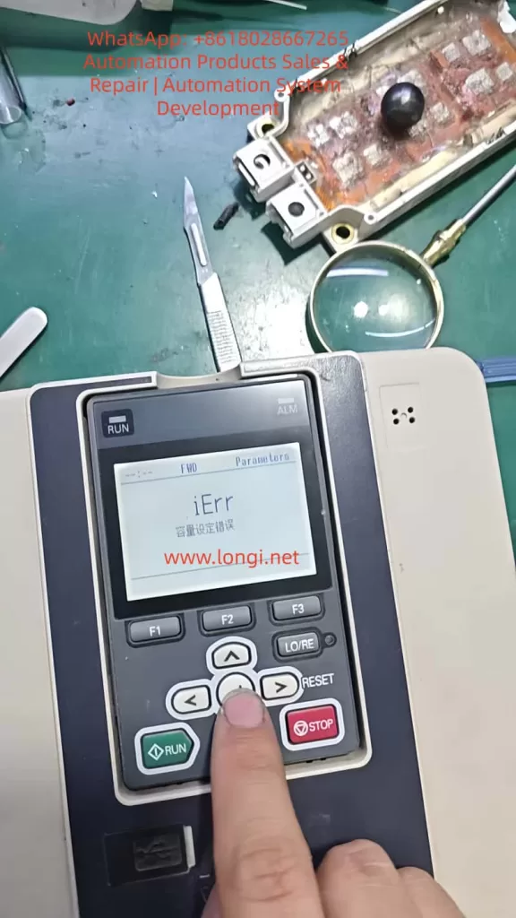
When servicing, commissioning, or restoring parameters on a Yaskawa GA700 inverter, technicians may encounter a common but easily misunderstood problem: when setting A1-03 = 2220 to perform 2-wire sequence initialization, the keypad does not complete initialization and instead displays iErr, meaning capacity setting error.
This error is often misjudged as a wrong key operation, insufficient access level, keypad failure, or corrupted software. In reality, for the GA700 series, the key issue is usually not A1-03 itself, but a mismatch between the inverter’s internal capacity setting and the actual power unit.
Yaskawa GA700 control boards have a certain level of interchangeability. In repair work, a control board may be taken from another GA700 unit and installed onto a different power section. However, “physically compatible” does not mean “automatically matched.” The control board must know the correct inverter capacity. If the capacity code stored in the control board does not match the actual power unit, the inverter may power up and display normally, but initialization, auto-tuning, or operation may fail.
1. What A1-03 = 2220 Actually Does
In GA700 parameters, A1-03 is the initialization parameter.
Common settings include:
1110: Initialize using user-saved parameters.2220: 2-wire sequence initialization.3330: 3-wire sequence initialization.
When A1-03 = 2220 is executed, the inverter restores many parameters to factory settings and assigns terminals S1 and S2 as forward run and reverse run inputs. However, this does not mean every parameter is reset. Several fundamental parameters are excluded from normal initialization, including capacity-related settings such as o2-04.
The important point is that “factory setting” is not one fixed parameter set for all GA700 drives. A 5.5 kW inverter, a 15 kW inverter, a 22 kW inverter, and a 75 kW inverter cannot share the same rated current, carrier frequency limit, overload curve, motor default values, or protection settings. Therefore, before the inverter can restore factory settings, it must first know its correct model and capacity.
If the capacity information is wrong, initialization cannot be safely completed.
2. The Real Meaning of iErr Capacity Setting Error
The iErr message is not a normal running fault such as overcurrent, overvoltage, undervoltage, or overload. It is closer to a parameter-processing error caused by failed capacity verification.
In simple terms, the inverter detects that:
the control board thinks it belongs to one capacity,
but the actual power unit appears to be another capacity,
or the capacity selection parameter has not been correctly written.
As a result, the inverter cannot safely generate the correct factory parameter set, so it refuses to complete initialization and displays iErr.
This protection logic is reasonable. If the inverter uses the wrong capacity data, it may apply the wrong rated current, wrong overload protection, wrong module thermal protection, wrong carrier frequency limit, and wrong control gain. The result may range from poor performance to IGBT damage, driver board damage, current detection errors, or motor damage.
The key parameter is:
o2-04 — Inverter Capacity Selection
This parameter sets the inverter model/capacity. After replacing the control circuit board, o2-04 must be correctly set according to the actual inverter model. If o2-04 is wrong, the protection functions may not operate correctly, and the inverter may be damaged.
Therefore, when A1-03 = 2220 causes iErr, the first parameter to check is not A1-03, but o2-04.
3. Why This Happens After Replacing the Main Control Board
Many technicians know that Yaskawa inverter control boards are often partly universal within the same series. This is true, but it must not be misunderstood.
The correct understanding is:
The control board may be hardware-compatible, but its capacity setting must match the actual power unit.
A GA700 inverter’s identity is determined by several items together:
- Nameplate model;
- Input voltage class;
- Rated output current;
- Power unit specification;
- Control board software version;
o2-04inverter capacity selection;C6-01heavy-duty/light-duty selection;- Capacity-dependent factory parameters.
If a control board is replaced but o2-04 is not corrected, the inverter may still power up, enter menus, and accept some parameter changes. However, problems may appear during initialization, auto-tuning, or trial operation. iErr during A1-03=2220 is a typical symptom.
4. o2-04 Is the Core Parameter
o2-04 is not a motor power parameter. It is not a parameter where the technician simply enters a motor kW value. It is a capacity selection code corresponding to the actual GA700 inverter model.
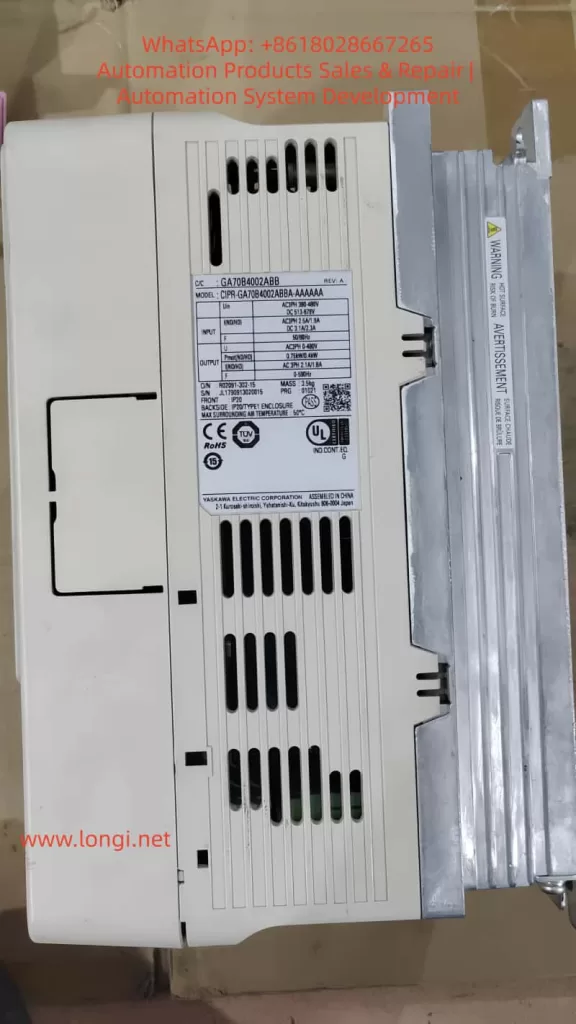
For example, for common 400 V class GA700 models:
| Inverter Model Suffix | o2-04 Setting |
|---|---|
| 4002 | 92 |
| 4004 | 93 |
| 4005 | 94 |
| 4007 | 95 |
| 4009 | 96 |
| 4012 | 97 |
| 4018 | 99 |
| 4023 | 9A |
| 4031 | 9C |
| 4038 | 9D |
| 4044 | 9E |
| 4060 | 9F |
| 4075 | A1 |
| 4089 | A2 |
| 4103 | A3 |
| 4140 | A4 |
| 4168 | A5 |
| 4208 | A6 |
| 4250 | A7 |
| 4296 | A8 |
| 4371 | A9 |
| 4389 | AA |
| 4453 | AC |
| 4568 | AD |
| 4675 | AE |
| 4810 | B0 |
| 4930 | B1 |
| 4H11 | B2 |
| 4H12 | B3 |
For example:
CIPR-GA70B4031 → o2-04 = 9CCIPR-GA70B4060 → o2-04 = 9FCIPR-GA70B4018 → o2-04 = 99
This value must be selected according to the inverter nameplate model, not according to the motor power at the site.
5. What Happens If o2-04 Is Set Incorrectly
Some people think the capacity parameter only affects the displayed model or rated power. This is dangerous.
An incorrect o2-04 setting may affect:
Rated Current Judgment
The drive’s overload protection, electronic thermal protection, and current limit are based on the correct inverter rated current. If a 15 kW inverter is set as a 7.5 kW unit, it may trip too early. If a 7.5 kW inverter is set as a 15 kW unit, protection may become too slow, and the power module may be damaged.
Carrier Frequency Limit
Different capacity drives have different allowable carrier frequency ranges. Larger drives generate more heat, and an excessive carrier frequency may cause the IGBTs to overheat.
Motor Default Parameters
After initialization, motor rated capacity, motor rated current, V/f base values, and other defaults may depend on the inverter capacity.
Protection Curves
Overload, overheat, module protection, and braking protection are all related to capacity. A wrong capacity setting may make protection inaccurate.
Control Performance
Vector control, current loop response, speed loop response, torque response, and low-speed performance all require correct capacity-based settings. If the capacity is wrong, the drive may still run, but it may show poor torque, vibration, overcurrent, unstable speed, or acceleration failure.
6. Correct Field Repair Procedure
When A1-03=2220 displays iErr, follow this procedure.
Step 1: Stop Repeating Initialization
Do not keep entering A1-03=2220. If the capacity data is wrong, repeating the same operation will not solve the problem.
Step 2: Check the Inverter Nameplate
Record the complete model number, especially:
- Full inverter model;
- Voltage class;
- Rated output current;
- Rated power;
- Production information;
- Whether it is a special version.
Example:
CIPR-GA70B4031xxxx
The key section is 4031.
Step 3: Set Parameter Access Level
Set:
A1-01 = 2
This allows access to advanced parameters. If the access level is too low, some parameters may not be visible or editable.
Step 4: Check Current o2-04
Enter parameter o2-04 and check whether the displayed value matches the nameplate model suffix.
Examples:
GA70B4018 → o2-04 = 99GA70B4023 → o2-04 = 9AGA70B4031 → o2-04 = 9CGA70B4038 → o2-04 = 9DGA70B4060 → o2-04 = 9F
If the value is obviously different, this is very likely the cause of iErr.
Step 5: Correct o2-04
Set o2-04 according to the actual inverter model.
After changing o2-04, power off the inverter. Wait until the CHARGE indicator is completely off and the DC bus voltage has dropped to a safe level. Then power on again.
This restart allows the drive to reload capacity-related internal settings.
Step 6: Execute A1-03 = 2220 Again
After power cycling, set:
A1-03 = 2220
If the capacity setting was the cause, initialization should now complete normally.
After initialization, recheck:
A1-02control method;C6-01heavy-duty/light-duty selection;- Motor rated voltage;
- Motor rated current;
- Motor rated frequency;
- Motor rated speed;
- Run command source;
- Frequency reference source;
- Acceleration/deceleration time;
- Multi-function terminal settings.
Do not assume that the drive is ready for load operation immediately after initialization. Application parameters must still be set correctly.
7. If iErr Still Appears After Correcting o2-04
If o2-04 matches the nameplate but A1-03=2220 still causes iErr, check deeper hardware and data issues.
Control Board and Power Board Version Mismatch
The control board may not be suitable for this voltage class, capacity range, or hardware version. Similar appearance does not guarantee compatibility.
Power Board Identification Circuit Problem
Some drives read capacity-related information from the power section, driver board, or internal identification circuit. Check:
- Control board-to-driver board ribbon cable;
- Connector oxidation;
- Bent pins;
- Loose or reversed cable connection;
- Low-voltage supply on the driver board;
- Identification resistors or related circuits.
EEPROM or Parameter Memory Error
If the drive has been affected by water, lightning, abnormal control power, failed repair, or incorrect programming, parameter memory may be corrupted. In this case, keypad operation may not be enough. The unit may require engineering software, special tools, EEPROM repair, or control board replacement.
Unknown Second-Hand Assembly
Used drives may be assembled from different units. The outer nameplate, control board, power board, and keypad may not belong to the same original inverter. In such cases, the technician must identify the actual power section rather than blindly trusting the nameplate.
Incorrect Capacity Code Entry
o2-04 values are not simple decimal numbers. Codes such as 9A, 9C, 9F, and A1 must be entered exactly. Misreading or mistyping these values will continue to cause problems.
8. Example Case
Suppose the nameplate shows:
CIPR-GA70B4031
This is a 400 V class GA700 with model suffix 4031. The corresponding o2-04 setting is 9C.
If a technician installs a control board taken from a GA70B4060, that control board may still store o2-04 = 9F. The drive may power on normally, but when A1-03=2220 is executed, it displays iErr.
The correct repair is:
- Set
A1-01 = 2; - Set
o2-04 = 9C; - Power off and wait until the CHARGE light goes out;
- Power on again;
- Set
A1-03 = 2220; - Reconfigure motor and application parameters.
If the initialization succeeds after this procedure, the original problem was capacity mismatch.
9. Common Mistakes to Avoid
Do not set o2-04 to a larger capacity just to avoid overload trips. This may delay protection and damage the inverter.
Do not set o2-04 according to motor power. It must be set according to the inverter’s actual model and power unit.
Do not assume initialization can fix capacity mismatch. Initialization itself depends on correct capacity data.
Do not skip power cycling after changing o2-04.
Do not ignore C6-01. Heavy-duty/light-duty selection affects rated current and overload characteristics.
10. Trial Operation After Repair
After correcting the capacity setting and completing initialization, perform a staged test.
First, power on the drive without load. Confirm that there is no fault, the keypad displays normally, the fan works normally, DC bus voltage is normal, and there is no abnormal smell or noise.
Second, check basic parameters, including:
A1-02 control method;b1-01 frequency reference source;b1-02 run command source;C1-01 acceleration time;C1-02 deceleration time;E1-01 input voltage setting;E1-04 maximum output frequency;E2-01 motor rated current;C6-01 heavy-duty/light-duty selection.
Third, run the motor without mechanical load at low frequency, such as 5 Hz, 10 Hz, and 20 Hz. Observe output current balance, motor rotation direction, vibration, and any abnormal alarm.
Fourth, gradually apply load. Do not immediately start with full load.
Fifth, perform motor auto-tuning if vector control or high-performance operation is required.
11. Professional Explanation for Customers
A clear explanation to the customer can be:
When the Yaskawa GA700 displays iErr during A1-03=2220 initialization, it indicates a capacity setting error. This is usually not caused by incorrect keypad operation or by the initialization command itself. The more likely cause is that the control board’s inverter capacity selection does not match the actual power unit. Although the GA700 control board has some interchangeability, after replacing the control board, parameter o2-04 must be set according to the actual inverter model. If the capacity setting is wrong, the drive cannot safely generate the correct factory parameter set, so it refuses initialization and displays iErr. The correct repair is to verify the nameplate model, set the proper o2-04 capacity code, power cycle the drive, and then execute A1-03=2220 again.
12. Conclusion
When a Yaskawa GA700 inverter reports iErr while setting A1-03=2220, the key point is not the initialization command itself but the inverter capacity selection parameter o2-04.
The GA700 control board may be reusable across certain models, but it must be matched to the actual power unit through the correct capacity code. If o2-04 is wrong, the inverter cannot safely restore factory parameters and will report a capacity setting error.
The correct repair logic is:
Check the inverter nameplate,
identify the model suffix,
set the correct o2-04,
power cycle the inverter,
execute A1-03=2220,
then reconfigure motor parameters and perform trial operation.
This fault looks like an initialization failure, but its real cause is usually a mismatch between the control board identity and the actual power unit capacity. For used GA700 drives, repaired units, replaced control boards, and mixed assemblies, this point is especially important.