
1. Background: When an SEM Cannot Work, the Electron Gun Is Not Always the Problem
A scanning electron microscope is a precision analytical instrument that depends heavily on a stable vacuum environment. For a field emission SEM such as the JEOL JSM-IT700HR/LA, the vacuum system is not just an auxiliary subsystem. It is one of the fundamental conditions that determines whether the instrument can enter observation mode.
When users report problems such as “the SEM cannot work,” “the software remains on the vacuum page,” “the system cannot enter observation,” or “there is no image,” the first suspicion is often directed toward the electron gun, high-voltage system, main computer, detector, or EDS analysis system. In many real service cases, however, the root cause is not located in the electron optical system. It is often related to the sample chamber, vacuum pump, vacuum valve, compressed air supply, vacuum sensor, or vacuum interlock logic.
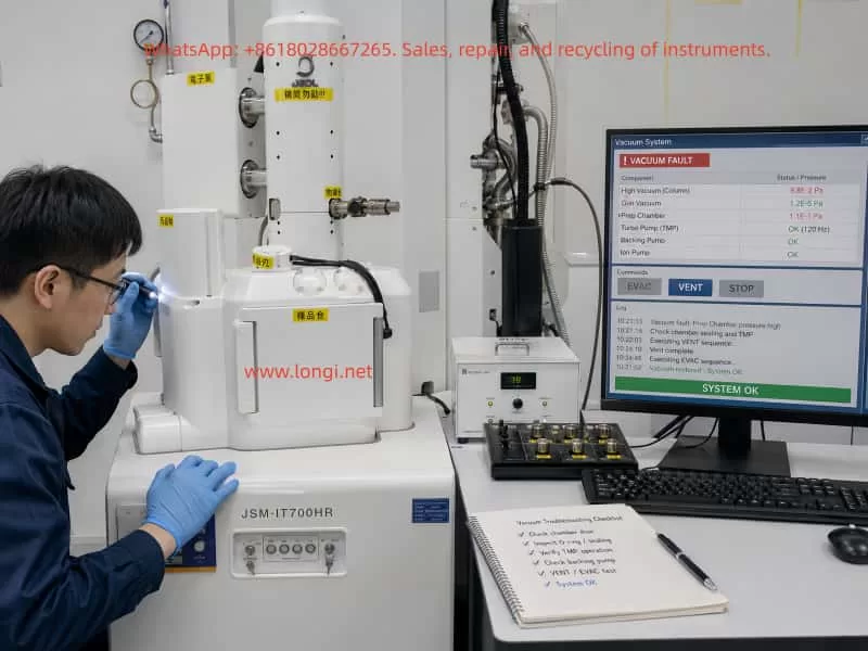
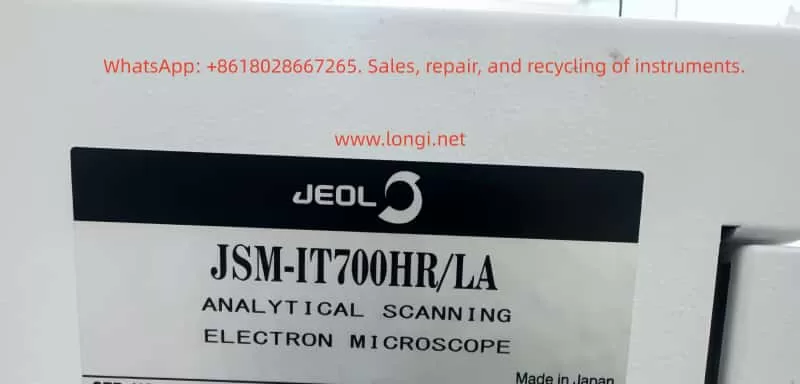
This article discusses a real troubleshooting case involving a JEOL JSM-IT700HR/LA analytical field emission scanning electron microscope. The customer provided several photos of the instrument and a video of the fault condition. The instrument software was stopped on the Vacuum System page, and the customer repeatedly pointed to a rear-side module related to the vacuum system. Based on the visual evidence and operating condition, the initial diagnosis was that the SEM had failed to complete the normal EVAC sequence, preventing the system from entering Observation mode.
After the customer followed a low-risk troubleshooting procedure involving the sample chamber door, O-ring, air supply, EVAC/VENT status, pump operation, and valve action, the instrument resumed normal operation. This confirmed that the fault was not a serious failure of the electron gun, EDS, display, or computer system. It was a typical vacuum interlock or vacuum sequence issue.
2. Instrument Overview: Why the JSM-IT700HR/LA Depends So Much on Vacuum Conditions
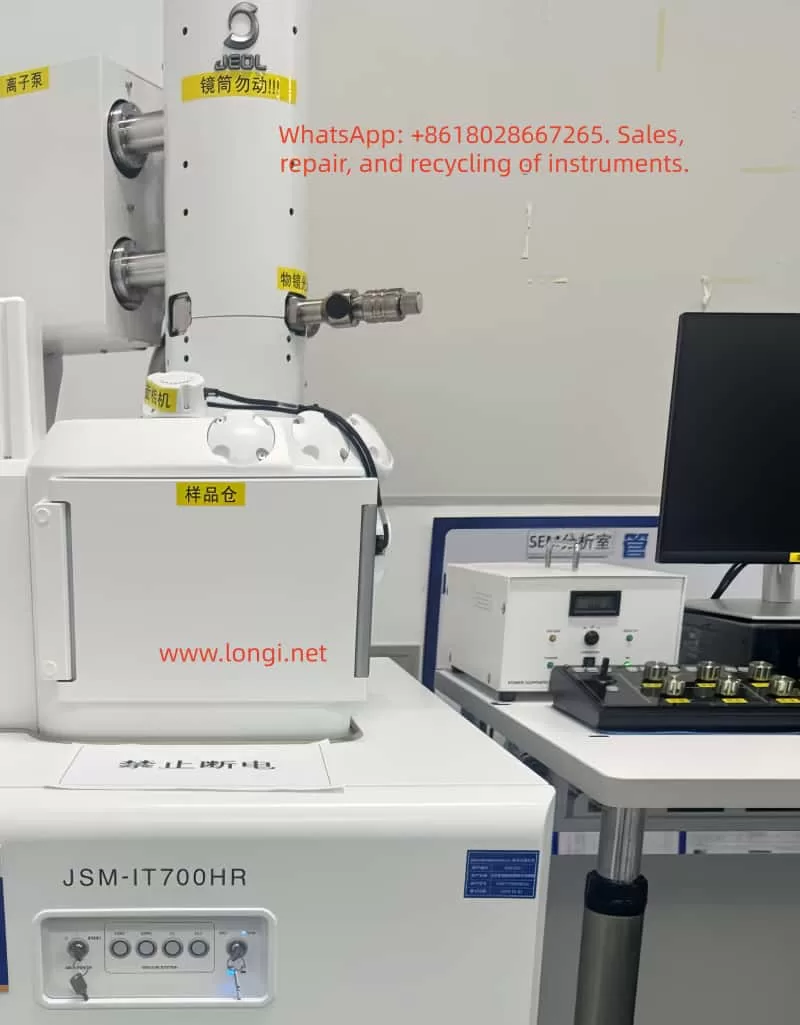
The JEOL JSM-IT700HR/LA is a high-performance field emission SEM with analytical capability. Compared with a conventional tungsten-filament SEM, a field emission SEM is much more sensitive to vacuum quality, especially around the electron gun, column, and sample chamber isolation system.
A typical configuration includes:
- Electron gun system
This generates the electron beam. A field emission gun is highly sensitive to contamination, moisture, and poor vacuum. It should never be forced to operate when the required vacuum has not been achieved. - Electron optical column
This includes condenser lenses, objective lens, scanning coils, stigmator system, and other beam control components. - Sample chamber
This is where the user loads samples. It is also the part of the instrument that is opened and closed most frequently, making it one of the most common sources of vacuum problems. - Vacuum system
This includes the roughing pump, turbo molecular pump, ion pump, vacuum valves, vent valve, gauges, pipelines, and pneumatic actuators. - Control system and software interface
The control software displays vacuum status, pump status, valve status, alarms, beam parameters, and imaging status. - EDS and analytical accessories
The “LA” configuration generally indicates an analytical version, often with an EDS system or related analytical hardware.
The key point is this: whether the SEM can enter Observation mode does not depend only on the computer or software. It depends on whether all vacuum, pump, valve, pressure, door, and high-voltage interlock conditions are satisfied.
Therefore, when the software stays on the Vacuum System screen, the first direction should be the vacuum system rather than the electron gun or main control board.
3. Fault Symptoms: The System Stayed on the Vacuum System Page
In this case, the video showed the SEM control interface displaying the vacuum system status diagram. Several important signs were visible:
- The software was stopped at the Vacuum System page.
- Status indicators such as VENT, EVAC, LV, and LLC were visible.
- The VENT/EVAC status did not appear to be in a normal completed state.
- Several valves, pumps, or vacuum paths appeared in abnormal colors.
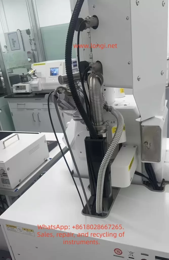
- The customer focused attention on a rear-side module with a fan and nearby control board.
- The system could not smoothly enter normal observation mode.
These signs indicate that the fault was not simply “no image.” The SEM had not completed its vacuum preparation sequence. Before a scanning electron microscope can generate an image, the sample chamber must be evacuated from atmospheric pressure to the required vacuum level. Only after the required pressure and valve conditions are satisfied will the instrument allow the system to open the necessary valves, enable the electron beam, and enter observation mode.
Therefore, the correct diagnostic question is not:
“Why is there no SEM image?”
The correct question is:
“Why did the sample chamber or column vacuum sequence fail to complete?”
This distinction is critical. Once the fault direction is correctly limited to the vacuum system, unnecessary work on the computer, monitor, EDS system, electron gun, or detector can be avoided.
4. Basic SEM Vacuum Sequence
To understand this type of fault, it is necessary to understand the normal vacuum sequence of an SEM.
A simplified operating sequence is as follows:
- The user presses VENT to bring the sample chamber to atmospheric pressure.
- The chamber reaches atmospheric pressure and the chamber door can be opened.
- The sample is loaded.
- The chamber door is closed.
- The user presses EVAC.
- The roughing pump starts to evacuate the sample chamber.
- The sample chamber pressure decreases.
- Vacuum valves switch in a defined sequence.
- The turbo molecular pump or high-vacuum system becomes effective.
- The pressure reaches the required range.
- The system allows Observation mode.
- The electron beam is enabled and imaging begins.
Every step is controlled by interlocks. The system may check:
- Whether the sample chamber door is closed.
- Whether the chamber is leaking.
- Whether the O-ring is sealing correctly.
- Whether the vent valve is fully closed.
- Whether the EVAC valve is open.
- Whether the roughing pump has started.
- Whether the backing pressure is suitable for the turbo pump.
- Whether the turbo pump has reached its required speed.
- Whether the vacuum gauges are giving reasonable feedback.
- Whether compressed air pressure is sufficient.
- Whether valve position feedback is correct.
- Whether the gun vacuum is safe for beam operation.
If any one of these conditions fails, the SEM may remain on the vacuum page and refuse to enter observation mode.
That is why an SEM vacuum fault often appears as a complete machine failure, even though the actual cause may be a small interlock condition.
5. Most Probable Causes in This Case
Based on the photos, the video, and the later successful recovery, the likely causes are concentrated in the following areas.
5.1 Sample Chamber Door Not Properly Sealed
The sample chamber door is one of the most common vacuum leak points in an SEM. It is opened and closed frequently, so its sealing surface and O-ring are exposed to dust, sample debris, carbon tape fragments, conductive adhesive, and mechanical wear.
Common problems include:
- The chamber door is not fully closed.
- The sample stage is too high and physically interferes with the chamber door.
- A sample holder, screw, or specimen edge touches the chamber wall.
- Dust or particles are present on the O-ring.
- Carbon tape, powder, metal particles, or adhesive remain on the sealing surface.
- The O-ring has cracks, compression marks, hardening, or deformation.
- The chamber door hinge or locking mechanism is slightly misaligned.
If the sample chamber door is not pulled inward by vacuum after pressing EVAC, or if evacuation takes much longer than usual, the first component to inspect should be the chamber door seal. In many cases, cleaning the O-ring and sealing surface is enough to restore normal evacuation.
5.2 VENT Valve Not Fully Closed
The VENT valve is used to admit air or nitrogen into the chamber so that the door can be opened. If the VENT valve does not fully close, the roughing pump will continuously pull against an air leak. The chamber pressure will not decrease properly.
A VENT valve problem may show the following symptoms:
- A slight air inlet sound after pressing EVAC.
- Very slow pressure decrease.
- Abnormal VENT status on the vacuum page.
- The system recovers after repeated VENT and EVAC operations.
- Intermittent valve sticking or poor sealing.
If the instrument recovers after repeated EVAC/VENT operation, the VENT valve or related pneumatic valve may have been sticking or not fully seated.
5.3 EVAC Valve or Pneumatic Valve Action Abnormal
The EVAC valve opens the evacuation path between the sample chamber and the pumping line. If the EVAC valve does not open, the pump may run but the chamber will not be evacuated.
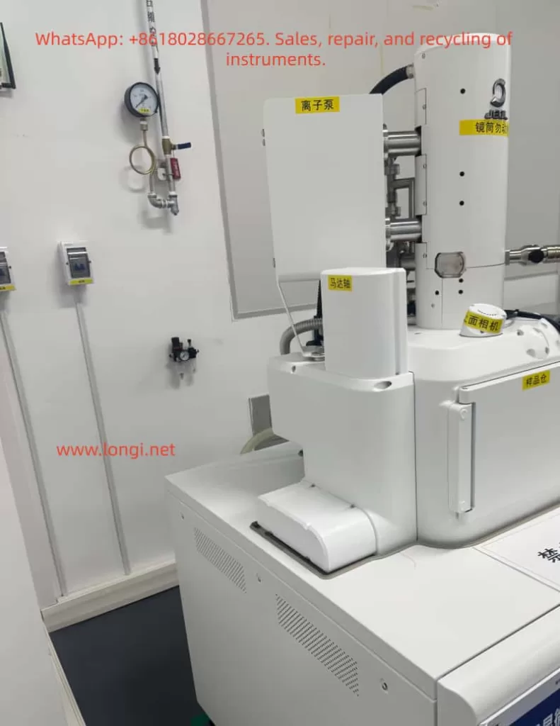
Many SEM vacuum valves are not directly driven by small solenoids alone. They may use compressed air through pneumatic actuators. The control board sends an electrical signal, the solenoid valve switches, and compressed air moves the vacuum valve. If compressed air pressure is insufficient, the software may command the valve to move, but the valve may not actually reach its correct position.
Therefore, the technician should check:
- Whether the compressed air supply is on.
- Whether the air pressure is within the required range.
- Whether the regulator is set correctly.
- Whether air tubing is loose or kinked.
- Whether the filter/regulator contains water.
- Whether a clear valve actuation sound can be heard when pressing EVAC or VENT.
- Whether the valve body is sticking.
- Whether valve position feedback is correct.
Low compressed air pressure can cause slow valve motion, incomplete valve travel, inconsistent feedback, or a vacuum sequence stop.
5.4 Roughing Pump or Dry Pump Not Starting Correctly
The roughing pump is essential for bringing the sample chamber down from atmospheric pressure to a low-vacuum level. If it does not start, or if its pumping capacity is severely reduced, the chamber cannot reach the conditions required for the next stage.
Typical symptoms include:
- No pump sound after pressing EVAC.
- Cooling fan runs but the pump does not actually pump.
- Pump body overheats.
- Pump control board has no output.
- A fuse is blown.
- Power cable or control cable is loose.
- The pump is worn and has reduced pumping speed.
- The roughing line is blocked or leaking.
In the video, the customer pointed to a rear module with a fan and nearby control board. This suggests that the on-site operator already suspected a module related to the pump, power supply, valve control, or vacuum I/O. It is important to confirm whether the pump is truly operating after EVAC, not merely whether a fan is spinning.
5.5 Turbo Molecular Pump or High-Vacuum System Not Reaching Required Conditions
For a field emission SEM, the high-vacuum section can only work normally after the roughing stage reaches an acceptable pressure. If the backing pressure is too high, the turbo molecular pump may not start correctly or may fail to reach rated speed.
A turbo pump-related issue may show:
- The roughing pump operates, but the pressure remains too high.
- TMP speed does not reach the required value.
- A TMP error or controller alarm appears.
- The vacuum sequence stops halfway.
- The system cannot enter high-vacuum mode or Observation.
However, in this case, because the instrument recovered after basic external checks, a serious turbo pump failure is less likely. A damaged turbo pump usually does not fully recover simply by cleaning the chamber seal or repeating the EVAC sequence.
5.6 Vacuum Sensor Feedback Abnormal
The vacuum control system depends on sensor feedback. If a vacuum gauge gives incorrect information, the SEM may refuse to proceed even if the actual pressure is acceptable.
Possible causes include:
- Contaminated vacuum gauge.
- Aging gauge.
- Loose sensor cable.
- Oxidized connector.
- Control board input fault.
- Abnormal sensor power supply.
- Software reading error.
For this kind of issue, it is not enough to look at the color of the vacuum diagram. The actual pressure values must be recorded, including:
- Chamber pressure.
- Column pressure.
- Gun pressure.
- Turbo pump speed.
- Ion pump current.
- Error log.
- Valve status.
If a pressure value does not change at all during evacuation, the sensor or its signal path should be suspected.
6. Why the Electron Gun or Main Board Should Not Be Disassembled First
High-end field emission SEM troubleshooting must follow a safe order: from external to internal, from low risk to high risk, from interlock conditions to core hardware.
The electron gun and column should not be opened without strong evidence.
There are several reasons:
- The field emission gun is extremely sensitive to contamination
Air exposure, moisture, particles, and oil vapor can cause unstable emission, low beam current, or permanent gun damage. - Column disassembly requires clean conditions and calibration
Random disassembly may introduce dust, mechanical misalignment, and vacuum contamination. - Forcing beam operation under poor vacuum is risky
Poor vacuum can cause high-voltage interlock, discharge, contamination, or emission instability. - When the system is stopped at the Vacuum System page, the electron optical system may not even be active yet
No image at this stage does not prove detector failure or electron gun failure. It may only mean that the system has not allowed beam operation. - Control board potentiometers must not be adjusted randomly
A visible trimmer or adjustable component on a control board may be used for threshold, feedback, drive calibration, or sensor adjustment. Without the service manual and original setting, it should not be turned.
Therefore, for this type of case, the correct approach is not to start with the most expensive component. The correct approach is to verify whether the most basic vacuum conditions are satisfied.
7. Recommended On-Site Troubleshooting Procedure
The following procedure can be used for SEM vacuum-related faults.
Step 1: Identify the Stage Where the Fault Occurs
The technician should first determine whether the problem occurs during:
- VENT;
- EVAC;
- transition to high vacuum;
- Observation entry;
- beam enable;
- imaging after the beam is already on.
Different stages correspond to different fault areas.
If the system is stuck on the Vacuum System page and cannot enter Observation, the vacuum system should be checked first.
Step 2: Observe Mechanical Response After Pressing EVAC
After pressing EVAC, observe:
- Does the roughing pump start?
- Is there a pump sound?
- Is the chamber door pulled tight by vacuum?
- Is there a valve actuation sound?
- Does the compressed air system move any valves?
- Does the chamber pressure decrease?
- Does the system produce an error message?
- Does it automatically return to VENT?
If there is no sound at all, check power, interlocks, pump control, and control signals.
If the pump runs but the door is not pulled inward, check for a large leak or EVAC valve failure.
If the door seals but the pressure decreases slowly, check for a small leak, weak pump, or leaking VENT valve.
Step 3: Inspect the Sample Chamber Seal
The recommended procedure is:
- Vent the chamber.
- Open the sample chamber.
- Remove the sample.
- Check whether the sample stage is too high.
- Inspect the sample holder, screws, and specimen edges.
- Inspect the chamber O-ring.
- Inspect the sealing surface.
- Clean the O-ring and sealing face carefully with suitable lint-free material.
- Close the chamber door again.
- Press EVAC and observe the result.
Do not use ordinary paper tissue that sheds fibers. Do not use aggressive solvent on the O-ring.
Step 4: Check the Compressed Air Supply
If the instrument uses pneumatic valves, compressed air must be checked.
Inspect:
- Air pressure.
- Air supply valve.
- Regulator setting.
- Loose air tubes.
- Kinked tubes.
- Water in the filter/regulator.
- Valve actuation sound during EVAC and VENT.
Insufficient air pressure is a hidden but common cause of SEM vacuum sequence failure. It may not always appear as a direct air pressure alarm, but it can stop valves from reaching their correct position.
Step 5: Check the Roughing Pump
Inspect:
- Whether the pump starts.
- Whether the pump sound is normal.
- Whether there is abnormal vibration.
- Whether the pump is overheating.
- Whether exhaust flow is present.
- Whether power input is normal.
- Whether the control cable is loose.
- Whether the fuse is blown.
- Whether the pipe connection is leaking.
- Whether the pump is overdue for maintenance.
If it is an oil pump, check oil level and oil condition. If it is a dry pump, check sound, temperature, and alarm indicators.
Step 6: Record Actual Vacuum Values and Error Logs
The technician should not rely only on colors in the vacuum diagram. Actual data should be recorded:
- Sample chamber pressure.
- Column pressure.
- Gun pressure.
- Roughing pressure.
- Turbo pump speed.
- Ion pump current.
- Valve status.
- Error log.
- Time required for evacuation.
These values help distinguish between leakage, weak pump performance, valve failure, and sensor feedback errors.
Step 7: Verify Repeatability
After recovery, the test should not stop immediately. Perform repeated cycles:
- VENT.
- Open and close the chamber.
- EVAC.
- Enter Observation.
- VENT again.
- EVAC again.
- Repeat at least two or three times.
If the sequence succeeds every time, the system is likely stable.
If the problem appears intermittently, there may still be valve sticking, air pressure fluctuation, poor sealing, or unstable sensor feedback.
8. Checks Required After the Instrument Recovers
In this case, the customer recovered the instrument after following the basic troubleshooting procedure. However, further verification is still necessary.
8.1 Check Evacuation Time
Record the time from pressing EVAC to reaching Observation-ready status. If this time becomes longer in future use, it may indicate a small leak or declining pump performance.
8.2 Save a Normal Vacuum System Screenshot
A screenshot of the normal Vacuum System page should be saved, including valve states, pump states, and pressure readings. This is an important reference for future troubleshooting.
8.3 Confirm Actual SEM Imaging
Vacuum recovery is only the first step. The user should also confirm:
- Observation mode can be entered.
- The electron beam is stable.
- An image can be obtained.
- Magnification change is normal.
- Focus works correctly.
- Stigmation adjustment is effective.
- Detector signal is normal.
- EDS or analytical functions work normally.
8.4 Watch for Recurrence
If EVAC failure returns soon after recovery, the likely suspects are:
- Aging O-ring.
- Leaking VENT valve.
- Sticking pneumatic valve.
- Fluctuating compressed air pressure.
- Reduced roughing pump performance.
- Unstable vacuum gauge.
- Loose connector on a vacuum control board.
9. Practical Value of This Case
This case demonstrates an important principle in high-end instrument repair:
Do not be intimidated by the complexity of the instrument. Understand the system logic first, then check the basic conditions.
Although the JSM-IT700HR/LA is a high-end field emission SEM, its vacuum control still follows basic physical logic. When the system cannot enter Observation mode, the first questions should be:
- Is the chamber door closed correctly?
- Is the O-ring clean?
- Has EVAC been executed properly?
- Is the VENT valve closed?
- Has the roughing pump started?
- Is compressed air pressure sufficient?
- Are the valves moving?
- Is the chamber pressure decreasing?
- Are the sensor readings reasonable?
These questions seem simple, but they solve many real SEM field failures. By contrast, immediately suspecting the electron gun, high-voltage power supply, main control board, or software may lead to misdiagnosis, unnecessary disassembly, and high repair risk.
In this case, the fact that the customer solved the fault through basic checks indicates that the actual problem was probably one of the following:
- Incomplete sample chamber sealing.
- VENT/EVAC sequence stuck.
- Pneumatic valve not fully actuated.
- Roughing pump or valve interlock temporarily abnormal.
- Vacuum system status restored after re-operation.
This is a vacuum sequence fault, not a core electron optical failure.
10. Preventive Maintenance Recommendations
To reduce recurrence of similar problems, laboratories should establish routine maintenance practices.
10.1 Check Sample Height Before Every Evacuation
A sample that is too high can interfere with the chamber, holder, or objective area. Large, irregular, or screw-mounted samples should be checked carefully.
10.2 Keep the Sample Chamber Clean
Sample powder, conductive adhesive, carbon tape fragments, and metal particles can affect sealing and contaminate the vacuum system. The chamber should be cleaned regularly.
10.3 Inspect the O-Ring Regularly
The O-ring is a consumable part. If it becomes cracked, flattened, hardened, or contaminated, it should be cleaned or replaced.
10.4 Avoid Unnecessary VENT/EVAC Cycling
Frequent venting and evacuation increase the workload on pumps, valves, and seals. Samples should be arranged in batches when possible.
10.5 Maintain Stable Compressed Air
Low or unstable air pressure can cause valve movement problems. Filters should be drained regularly, and the regulator setting should remain stable.
10.6 Record Normal Vacuum Parameters
A maintenance log should include:
- Evacuation time.
- Sample chamber pressure.
- Column pressure.
- Gun pressure.
- TMP status.
- Ion pump status.
- Alarm history.
When a fault occurs, these records help compare normal and abnormal conditions.
10.7 Do Not Adjust Internal Boards Without Evidence
Potentiometers, jumpers, and internal control settings should not be changed randomly. Any adjustment should be supported by service documentation and original position records.
10.8 Do Not Force Beam Operation Under Poor Vacuum
Operating the electron beam under poor vacuum conditions can cause contamination, discharge, emission instability, and possible gun damage. Vacuum conditions must be restored first.
11. Common Symptoms and Diagnostic Directions
| Symptom | Possible Cause | Priority Check |
|---|---|---|
| No sound after pressing EVAC | Pump not starting, power fault, control signal fault | Pump power, fuse, interlock, control board |
| Pump runs but chamber door is not pulled tight | Large leak, door not closed, EVAC valve not open | Chamber door, O-ring, valve, air supply |
| Chamber seals but evacuation is slow | Small leak, weak pump, leaking VENT valve | O-ring, pipeline, pump performance, VENT valve |
| System returns to VENT after evacuation attempt | Vacuum not achieved, valve feedback error, protection | Error log, valve state, sensor readings |
| Turbo pump does not reach speed | Backing pressure too high, TMP controller fault | Roughing pump, TMP controller, pressure values |
| Vacuum value does not change | Gauge or signal problem | Sensor, cable, connector, control board input |
| Intermittent success and failure | Sticking valve, air pressure fluctuation, bad connection | Air supply, valve body, connectors, sealing |
| Vacuum normal but no image | Beam, detector, or parameter issue | HV, beam current, working distance, detector |
12. Conclusion
When a JEOL JSM-IT700HR/LA scanning electron microscope cannot operate normally and the software remains on the Vacuum System page, especially with abnormal VENT, EVAC, LV, LLC, valve, or pump status, the first diagnostic direction should be the vacuum system. It is not correct to immediately assume that the electron gun, EDS system, main computer, or display system is damaged.
In this case, the instrument recovered after basic checks, which strongly indicates that the root cause was related to chamber sealing, VENT/EVAC valve status, compressed air, roughing pump operation, or vacuum interlock conditions.
The correct troubleshooting sequence is:
Check the sample chamber seal first, then the compressed air supply, then the pump, then the valves, then the actual pressure values and error logs. Only after these checks should deeper hardware faults such as sensors, control boards, or high-vacuum components be considered.
For a field emission SEM, vacuum is the foundation of operation. If the vacuum sequence is not completed, the system will not allow normal observation. Many faults that look like serious whole-machine failures are actually caused by a dirty O-ring, an incompletely closed vent valve, insufficient air pressure, a slow valve, or a failed EVAC sequence.
The safest and most effective repair strategy is not blind disassembly, but understanding the interlock logic of the instrument. By checking the vacuum process step by step, many SEM field failures can be restored without opening the electron gun, disturbing the column, or replacing expensive components.