
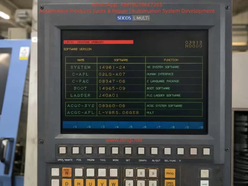
Hitachi Seiki HT 23R III is a typical medium-sized CNC lathe equipped with the SEICOS L MULTI / SEICOS MULTI control system. On this type of machine, when the control screen starts normally and the software version page can be displayed, but the alarm line shows L2191 MACHINE UNREADY, the problem usually does not mean that the NC system has completely failed. It more often indicates that the machine-side ready conditions have not been satisfied.
In practical maintenance, this alarm should be understood as follows: the CNC control has powered up, the screen and basic system software are running, but the machine tool has not entered the fully ready state required for servo enable, spindle operation, axis movement, tool indexing, or automatic cycle operation. The NC system is waiting for the PLC and machine-side interlock chain to confirm that all necessary conditions are normal.
For an old CNC lathe such as the Hitachi Seiki HT 23R III, the “Machine Ready” condition is not a single signal or a single pushbutton. It is a combined result of many hardware and PLC logic conditions, including the emergency stop circuit, safety door, hydraulic pressure, lubrication, air pressure, chuck clamping confirmation, turret locking, servo drive ready signal, spindle drive ready signal, overload relays, 24 VDC control power, and PLC output permission. If any one of these conditions is missing, the system may display L2191 MACHINE UNREADY.
This article explains the meaning, diagnostic logic, common causes, and practical troubleshooting method for the Hitachi Seiki HT 23R III CNC lathe when it reports the L2191 MACHINE UNREADY alarm.
1. Fault Phenomenon and Basic Meaning of the Alarm
A typical fault condition is as follows:
The machine is powered on. The CRT or operator screen lights up normally. The SEICOS MULTI system page can be displayed. The software version information, ladder version, boot software, and system software can be read. However, the alarm area shows:
L2191 MACHINE UNREADY
This situation is different from a completely dead NC system. If the screen can display the software version page, it means that the NC control, display unit, boot software, and basic human-machine interface have at least started successfully. Therefore, the first diagnostic direction should not be direct replacement of the NC CPU board or display unit.
The alarm means that the CNC system has not received the machine ready confirmation from the machine-side control logic. In other words, the PLC has not judged the machine as ready, or the ready signal has not been returned to the NC system.
The phrase “Machine Unready” is broad. It does not directly point to one failed component. It is a result alarm, not a component-level alarm. The actual cause may be located in the electrical cabinet, hydraulic system, lubrication unit, spindle drive, servo drive, safety circuit, turret mechanism, chuck clamping circuit, pressure switch, proximity switch, relay, contactor, or PLC input/output circuit.
For this reason, the correct maintenance method is not to replace parts blindly, but to trace the machine ready condition chain step by step.
2. Control Structure of the Hitachi Seiki HT 23R III
The Hitachi Seiki HT 23R III generally uses a SEICOS MULTI series control system. The control structure of this type of CNC lathe can be divided into several levels.
The first level is the NC control level. It handles coordinate control, program interpretation, interpolation, tool offset, spindle command, axis command, and screen display.
The second level is the PLC / ladder logic level. It controls the machine-side logic, such as hydraulic pump start, lubrication pump operation, chuck clamp confirmation, turret indexing, turret lock confirmation, tailstock movement, door interlock, coolant pump, chip conveyor, spindle permissive signals, and alarm collection.
The third level is the drive and actuator level. This includes the X-axis servo drive, Z-axis servo drive, spindle drive, hydraulic pump motor, contactors, relays, solenoid valves, pressure switches, limit switches, proximity switches, and other field components.
The fourth level is the safety and ready interlock level. This includes emergency stop, control power, servo enable, spindle ready, hydraulic pressure ready, lubrication ready, air pressure ready, turret lock ready, chuck clamp ready, and other conditions required before machine operation is allowed.
The L2191 MACHINE UNREADY alarm usually occurs between the PLC logic level and the safety/ready interlock level. The NC system has started, but the PLC has not completed the machine ready logic. Therefore, the troubleshooting focus should be on machine-side signals, PLC inputs, relays, drives, hydraulic conditions, and safety circuits.
3. Typical Machine Ready Logic Chain
On a CNC lathe, the Machine Ready signal is usually generated only after a series of conditions are satisfied. A simplified logic chain may look like this:
Main control power normal → Emergency stop circuit closed → Safety door condition normal → 24 VDC control power normal → PLC running normally → Hydraulic pressure established → Lubrication condition normal → Servo and spindle drives ready → Turret locked → Chuck clamping confirmation normal → Machine Ready output established
Different machine versions may use different logic, but the basic principle is the same. If one condition is missing, the machine cannot enter the ready state.
For the Hitachi Seiki HT 23R III, the following conditions should be checked carefully.
4. Emergency Stop Circuit
The emergency stop circuit is the first and most important condition. On an old CNC lathe, the emergency stop button may not only be on the main operator panel. It may also be located on the electrical cabinet, tailstock area, chuck area, chip conveyor, hydraulic unit, bar feeder interface, or robot interface.
If the emergency stop circuit is open, the NC system may still power up and display normally, but the machine will not allow servo power, spindle operation, hydraulic operation, or axis movement.
The following points should be checked:
All emergency stop buttons should be released.
After releasing the emergency stop buttons, the RESET button should be pressed.
The emergency stop relay or safety relay inside the electrical cabinet should be checked.
The PLC input corresponding to emergency stop should be checked.
External machine interfaces should be inspected. If the machine was disconnected from a bar feeder, robot, loader, or chip conveyor, the emergency stop loop at the external interface may be open.
During machine relocation, emergency stop wiring, cabinet connectors, or interface plugs may become loose. This is especially common on imported second-hand machines. Therefore, even if the emergency stop button appears released, the actual emergency stop chain must still be verified electrically.
5. Control Power and 24 VDC Supply
A common mistake is assuming that the entire electrical system is normal just because the NC screen is on. In reality, the NC control power and the machine control power may be different circuits.
Old CNC lathes may use several control voltages, such as AC 100 V, AC 110 V, AC 200 V, DC 24 V, and other auxiliary supplies. PLC inputs, proximity switches, relays, solenoid valves, pressure switches, safety relays, and interface circuits often depend on 24 VDC control power.
If the 24 VDC power supply is low, unstable, missing, overloaded, or has blown fuses, the PLC may fail to receive the required ready signals. The machine may then remain in the Machine Unready state.
The following measurements should be performed with a multimeter:
Measure the output of the 24 VDC power supply.
Measure the 24 VDC supply at the PLC input common terminals.
Measure the power supply to the proximity switches and pressure switches.
Check whether any fuses or circuit breakers are open.
Check whether the 24 VDC voltage drops when the Machine Ready button is pressed.
Check terminal blocks for loose screws, oxidation, or broken wires.
The power indicator on a power supply is not enough. The voltage must be measured under load. A weak 24 VDC supply may still turn on its indicator lamp, but fail when relays or solenoids are energized.
6. Hydraulic System and Hydraulic Pressure Confirmation
The hydraulic system is one of the most important ready conditions on a CNC lathe. The Hitachi Seiki HT 23R III typically uses hydraulic functions for the chuck, turret, tailstock, spindle braking, or other auxiliary mechanisms, depending on configuration.
If the hydraulic pump does not start, the hydraulic pressure is too low, or the pressure switch does not confirm pressure, the machine will not become ready.
The following hydraulic-related faults are common:
Hydraulic pump motor does not start.
Hydraulic pump contactor does not energize.
Thermal overload relay has tripped.
Three-phase power is missing or phase sequence is wrong.
Hydraulic oil level is too low.
Hydraulic pump is worn or damaged.
Oil suction filter is blocked.
Relief valve setting is too low.
Hydraulic pressure switch is faulty.
Hydraulic pressure switch setting is incorrect.
Hydraulic pressure is present, but the pressure signal does not reach the PLC.
Hydraulic pipe leakage causes pressure loss.
The correct diagnostic method is to first observe whether the hydraulic pump starts. If it does not start, check the electrical control circuit of the pump, contactor, overload relay, motor, and PLC output. If the pump runs but there is no pressure, check the oil level, pump suction, filter, relief valve, and pump condition.
If the pressure gauge shows normal pressure but the alarm remains, the pressure switch and its PLC input must be checked. This is a very common fault: the machine has hydraulic pressure physically, but the control system does not receive the hydraulic ready signal.
In this case, the technician should check whether the pressure switch contact changes state, whether the signal reaches the terminal block, and whether the corresponding PLC input indicator turns on.
7. Lubrication System
The lubrication system can also prevent Machine Ready. CNC lathes require lubrication for guideways, ball screws, turret mechanisms, and other moving parts. The machine may monitor lubrication oil level, lubrication pump operation, or lubrication pressure.
Common lubrication-related problems include:
Lubrication oil level is too low.
Lubrication pump does not operate.
Lubrication pressure switch does not activate.
Lubrication line is blocked.
Lubrication pump motor or coil is defective.
Low oil level switch is stuck.
Lubrication relay or PLC output is faulty.
If the lubrication ready condition is not satisfied, the machine may remain in the unready state even if the NC system, hydraulic pump, and drives appear normal.
On older machines, lubrication oil may become dirty or thick after long storage. Oil lines may be blocked. Low-level float switches may stick. Therefore, lubrication should not be ignored when troubleshooting Machine Unready alarms.
8. Air Pressure and Safety Door Interlock
Some CNC lathes use compressed air for door locks, air blow, chuck confirmation, tailstock operation, measuring devices, or auxiliary systems. If air pressure is too low or the pressure switch is not activated, the machine ready chain may not be completed.
The safety door is another important interlock. Depending on the original configuration or later safety modification, the door lock may be part of the machine ready logic. If the door is open, the door switch is damaged, or the door proximity switch is misaligned, the machine may not enter ready state.
For second-hand machines imported from another country, the safety door circuit may have been modified. Sometimes safety switches are bypassed improperly, or external safety interfaces are left open after accessories are removed. These problems can directly cause Machine Unready.
Safety circuits should never be permanently shorted as a repair method. Temporary bypassing for diagnosis should only be performed by qualified personnel and only under controlled conditions. During normal machine operation, all safety devices must be restored to proper function.
9. Servo Drive and Spindle Drive Ready Signals
The machine ready logic often requires the servo drives and spindle drive to report ready status. If the X-axis servo drive, Z-axis servo drive, spindle drive, servo power module, regenerative unit, encoder feedback, cooling fan, or thermal protection circuit has an alarm, the PLC may not receive the drive ready signal.
Common drive-related problems include:
Servo drive alarm.
Spindle drive alarm.
Servo power supply undervoltage.
Main contactor does not energize.
Regenerative braking unit fault.
Encoder cable loose or damaged.
Servo motor overheat.
Drive cooling fan fault.
DC bus voltage abnormal.
Axis overtravel.
Axis position shifted during transport.
For this reason, when the NC screen only displays L2191 MACHINE UNREADY, the technician must still open the electrical cabinet and check all drive displays. The actual root cause may be shown on the servo drive or spindle drive, not on the NC screen.
For example, a spindle drive may show an undervoltage or overcurrent alarm, while the NC screen only summarizes the situation as Machine Unready. Similarly, an X-axis servo drive encoder fault may prevent the ready chain from completing.
Recording all drive alarm codes is essential before making any repair decision.
10. Axis Overtravel and Machine Position After Transportation
Old CNC lathes are often transported long distances. During transportation, the X or Z axis may move slightly due to vibration, lifting angle, or mechanical impact. If an axis presses a hard limit switch or enters an overtravel state, the machine may not become ready.
Possible symptoms include:
Axis is at the extreme end of travel.
Overtravel switch is pressed.
Limit switch roller is stuck.
Limit switch cable is broken.
Axis position is beyond the software travel range.
Servo cannot enable because the axis is in an unsafe position.
The technician should visually inspect the X and Z axis positions and check the limit switches. If the machine is in overtravel, the correct overtravel release procedure must be followed according to the machine manual. It is not recommended to force axis movement without understanding the control logic and mechanical condition.
11. Turret Lock Confirmation
The turret is one of the most important mechanisms on a CNC lathe. If the turret is not fully locked, the machine may not become ready. A turret that appears mechanically in position may still fail to provide the correct lock confirmation signal.
Typical turret-related causes include:
Turret stopped between stations.
Turret index did not complete.
Turret lock hydraulic pressure is low.
Turret lock proximity switch is faulty.
Turret position encoder is faulty.
Turret motor overload relay tripped.
Turret mechanism is jammed.
Turret clamp/unclamp cylinder does not move correctly.
Oil contamination affects proximity switch operation.
When troubleshooting, the technician should not judge only by visual inspection. The turret lock signal must be checked at the PLC input. If the turret lock input is not active, the PLC will not allow Machine Ready even if the turret looks locked from outside.
12. Chuck Clamping Confirmation
The chuck clamping signal is another critical condition. A CNC lathe usually requires confirmation that the chuck is properly clamped before spindle operation or automatic cycle. Depending on the machine logic, missing chuck clamp confirmation may also prevent the machine from entering full ready state.
Common chuck-related problems include:
Hydraulic chuck pressure too low.
Chuck clamp pressure switch faulty.
Drawtube cylinder stroke switch not activated.
Chuck clamp/unclamp confirmation switch damaged.
Foot pedal switch faulty.
Internal/external clamping mode selection incorrect.
PLC input does not receive the chuck clamp signal.
Hydraulic leakage inside chuck cylinder.
In troubleshooting, the hydraulic pressure should be checked first. Then the clamp/unclamp confirmation switches and their PLC input signals should be verified.
A very common situation is that the chuck physically clamps the workpiece, but the confirmation switch does not send the correct signal to the PLC. In that case, the machine logic still considers the chuck unsafe.
13. Why the NC Screen Can Work While the Machine Is Still Unready
It is important to distinguish between “NC power on” and “machine ready.”
A CNC lathe has several power and control stages:
The first stage is NC control power. The screen turns on, the control software starts, and menus can be displayed.
The second stage is machine control power. PLC modules, relays, contactors, sensors, solenoids, and auxiliary circuits receive power.
The third stage is machine ready. All safety, hydraulic, lubrication, drive, turret, chuck, and position conditions are satisfied.
The L2191 MACHINE UNREADY alarm means the machine has passed the first stage but has not completed the third stage. Therefore, the troubleshooting focus should be on the machine-side ready chain instead of immediately suspecting the NC CPU board.
14. Standard Troubleshooting Procedure
Step 1: Record the Current Alarm and Machine State
Before switching power off, the technician should record the alarm page, alarm number, machine mode, status codes, and whether the alarm changes after pressing RESET.
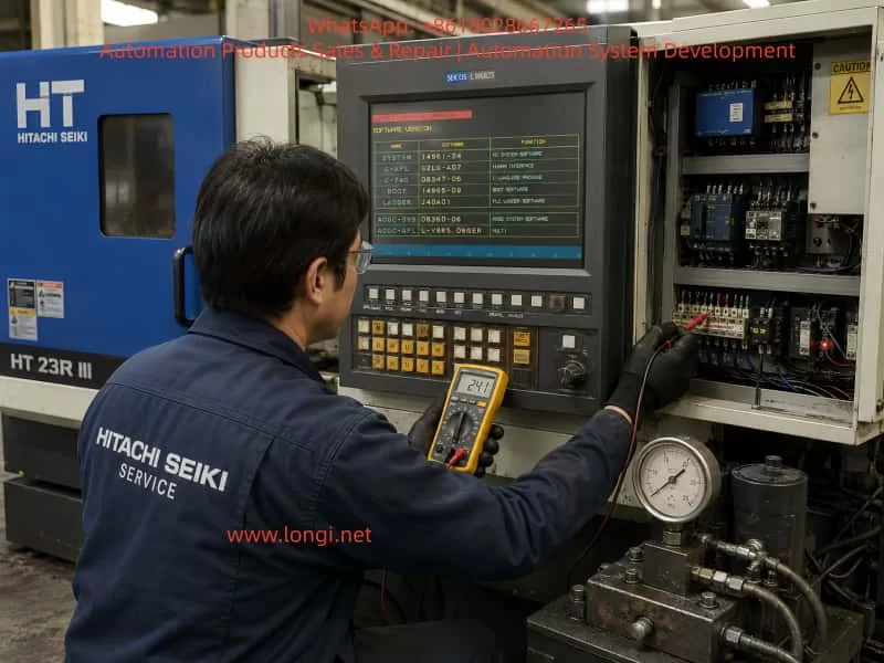
It is also important to observe whether any contactor energizes when the Machine Ready, Power On, or Servo On button is pressed. Listen for relay or contactor movement inside the electrical cabinet. Check whether the hydraulic pump starts. Check whether any alarm lamps are on inside the electrical cabinet.
If there are multiple alarms, handle the most basic safety, emergency stop, and power supply alarms first.
Step 2: Check Emergency Stop and Safety Chain
Release all emergency stop buttons and press RESET. Check the emergency stop relay and safety relay. Verify whether the corresponding PLC input changes state.
If the machine has external interfaces for a bar feeder, loader, robot, or chip conveyor, check whether the safety contacts are properly connected. Many second-hand machines fail to become ready because an external emergency stop loop is open after accessory removal.
Step 3: Check Control Power
Measure all important control voltages, especially 24 VDC. Check fuses, circuit breakers, terminal blocks, relays, and power supply outputs.
Do not rely only on indicator lights. Use a multimeter and measure the voltage under actual load.
Step 4: Check Hydraulic System
Confirm whether the hydraulic pump starts. If not, check the pump contactor, overload relay, motor, PLC output, and control circuit.
If the pump starts but pressure is low or zero, check oil level, filter, pump suction, relief valve, and hydraulic leakage.
If pressure is normal, check the hydraulic pressure switch and its PLC input signal.
Step 5: Check Servo and Spindle Drives
Open the electrical cabinet and record all alarm codes from the servo drives, spindle drive, and power modules. The NC screen may not display the detailed drive alarm.
If any drive is not ready, solve that drive fault first.
Step 6: Check Axis Limit Switches
Inspect whether the X or Z axis is pressing a limit switch. Check positive and negative overtravel switches. Verify the overtravel signal at the PLC input.
If the machine is in overtravel, follow the correct release procedure.
Step 7: Check Turret and Chuck Signals
Verify turret lock confirmation and chuck clamp confirmation at the PLC input level. Do not rely only on mechanical appearance. If the PLC does not receive the confirmation signal, the ready chain will remain open.
Step 8: Use PLC Input/Output Diagnosis
If the electrical cabinet has PLC input indicator lights, use them to verify each ready condition.
Check whether the input changes when:
Emergency stop is released.
Safety door is closed.
Hydraulic pressure is established.
Lubrication pressure is established.
Air pressure is normal.
Turret is locked.
Chuck is clamped.
Drives are ready.
If ladder monitoring is available, trace the Machine Ready coil and identify which contact in the logic chain is not satisfied. This is the most accurate method.
15. Common Fault Points and Repair Directions
Hydraulic Pump Does Not Start
If the hydraulic pump does not run and the pressure gauge stays at zero, check the pump contactor, thermal overload relay, motor, three-phase power, and PLC output.
If the contactor does not energize, the fault is likely in the control circuit. If the contactor energizes but the motor does not rotate, check the motor and main power. If the motor rotates but no pressure builds, check the oil pump, oil level, suction line, filter, and relief valve.
Hydraulic Pressure Exists but PLC Does Not Receive the Signal
If the pressure gauge shows normal pressure but the machine remains unready, check the pressure switch, wiring, terminal blocks, and PLC input. The pressure switch may need adjustment or replacement.
Emergency Stop Chain Open
If pressing Machine Ready produces no contactor action and the servo system does not power up, check emergency stop buttons, safety relays, door switches, external interface jumpers, and relay contacts.
Servo or Spindle Drive Alarm
If any drive shows an alarm, repair that drive fault first. Possible causes include encoder failure, motor fault, undervoltage, overcurrent, fan failure, regenerative unit fault, or power module fault.
Turret Not Locked
If the turret is between stations or the turret lock signal is missing, check the turret motor, turret hydraulic clamp, position encoder, lock switch, and turret mechanism.
Chuck Clamp Signal Abnormal
If the chuck is physically clamped but the machine does not recognize it, check the hydraulic pressure, clamp confirmation switch, drawtube cylinder switch, clamp/unclamp mode, and PLC input.
Lubrication Alarm
If the lubrication condition is not satisfied, check oil level, lubrication pump, pressure switch, low-level switch, and lubrication lines.
24 VDC Power Supply Fault
If multiple input signals are missing at the same time, check the 24 VDC supply, fuses, common terminals, sensor supply, and shorted field devices.
16. Common Misdiagnoses
Misdiagnosis 1: Assuming the Machine Is Electrically Normal Because the Screen Works
A working screen only proves that the NC control has started. It does not prove that the hydraulic system, safety circuit, PLC inputs, drives, or machine ready chain are normal.
Misdiagnosis 2: Replacing the NC Main Board Too Early
Most Machine Unready alarms are caused by peripheral ready conditions, not NC CPU board failure. The NC board should only be suspected after power, safety, hydraulic, drive, and PLC I/O conditions have been confirmed.
Misdiagnosis 3: Only Pressing RESET Without Following the Correct Power-On Sequence
Many old CNC machines require a specific sequence: main power, NC power, hydraulic start, Machine Ready, Servo On, and RESET. If the operator does not follow the correct sequence, the machine may appear faulty even when no component is damaged.
Misdiagnosis 4: Judging by Mechanical Appearance Only
A turret may look locked, a chuck may look clamped, and hydraulic pressure may appear normal. But if the corresponding confirmation signals do not reach the PLC, the machine will still remain unready.
Misdiagnosis 5: Permanently Bypassing Safety Signals
Safety signals should not be permanently shorted. Emergency stop, door interlock, chuck clamp confirmation, and hydraulic pressure confirmation are safety-critical. Bypassing them may cause unexpected spindle start, axis movement, or workpiece ejection.
17. Recommended On-Site Inspection Checklist
For a Hitachi Seiki HT 23R III with L2191 MACHINE UNREADY, the following checklist is recommended:
Record the NC alarm page and software version page.
Confirm that all emergency stop buttons are released.
Press RESET and observe whether the alarm changes.
Press Machine Ready / Power On / Servo On and listen for contactor action.
Check whether the hydraulic pump starts.
Check the hydraulic pressure gauge.
Check lubrication oil level and lubrication pump operation.
Check air pressure and air pressure switch.
Check the safety door and door lock switch.
Open the electrical cabinet and record servo drive and spindle drive alarms.
Check thermal overload relays.
Measure 24 VDC control power.
Check PLC input indicators.
Check whether X or Z axis is pressing an overtravel switch.
Check turret lock confirmation.
Check chuck clamp confirmation.
Trace the Machine Ready condition in the electrical diagram or ladder logic.
If ladder monitoring is available, identify which contact prevents the Machine Ready coil from turning on.
This troubleshooting process follows a clear principle: start from safety and power, then check hydraulic and drive conditions, then verify machine-side confirmation signals through PLC inputs, and finally consider NC or PLC board-level faults only if all field conditions are proven normal.
18. Repair Cost and Spare Parts Consideration
The L2191 MACHINE UNREADY alarm alone is not enough to determine the repair cost. It is only a general machine status alarm. The final cost depends on the actual failed component.
If the cause is an unreleased emergency stop, open safety door, low hydraulic oil, tripped overload relay, or missing external interface jumper, the repair cost may be low and mainly involve labor and adjustment.
If the cause is a pressure switch, proximity switch, relay, contactor, 24 VDC power supply, lubrication pump, or minor wiring fault, the cost is moderate and the parts are usually replaceable.
If the cause is a servo drive, spindle drive, power module, PLC I/O board, NC interface board, or SEICOS system board, the cost can be much higher. Spare parts for older Hitachi Seiki machines may be difficult to source, and compatibility must be verified carefully.
If the cause is turret mechanical jamming, hydraulic pump failure, spindle drive failure, lost parameters, or ladder program issues, the repair may require deeper on-site troubleshooting and machine-specific documentation.
Therefore, when only a screen photo is available, the correct conclusion is: the machine is not ready, and the most likely direction is a missing machine-side ready condition. However, the exact failed component cannot be confirmed without checking the electrical cabinet, hydraulic pressure, drive displays, PLC inputs, and interlock signals.
19. Practical Diagnostic Logic for Field Engineers
A practical diagnostic logic for this type of fault can be summarized as:
Do not start by replacing the NC board.
Do not judge only from the NC screen.
Do not ignore hydraulic pressure and pressure switch feedback.
Do not ignore safety door, emergency stop, and external accessory interfaces.
Do not trust mechanical appearance without checking PLC inputs.
Do not bypass safety circuits as a final solution.
Always trace the ready condition chain from the machine side back to the PLC.
In real maintenance, the fastest way is to identify which ready condition is missing. If the machine has ladder monitoring, locate the Machine Ready coil and inspect the preceding contacts. If ladder monitoring is not available, use PLC input indicators and an electrical diagram to check the ready chain one signal at a time.
The key question is not simply “Why does the screen show Machine Unready?” The real question is: Which required ready condition has not been confirmed by the PLC?
Once this question is answered, the fault becomes much easier to repair.
20. Conclusion
When a Hitachi Seiki HT 23R III CNC lathe displays L2191 MACHINE UNREADY, the essential meaning is that the machine ready conditions have not been completed. The alarm usually does not indicate a machining program problem, and it should not immediately be judged as NC control board failure.
Because this type of CNC lathe includes hydraulic chuck operation, turret locking, servo axes, spindle drive, lubrication, safety interlocks, and multiple PLC confirmation signals, the Machine Ready state depends on many conditions working together. The common causes include emergency stop circuit open, missing 24 VDC control power, hydraulic pump not starting, hydraulic pressure switch not confirming, lubrication failure, air pressure failure, safety door interlock problem, servo or spindle drive alarm, turret not locked, chuck clamp signal missing, overtravel switch active, relay fault, contactor fault, or PLC input signal failure.
The correct troubleshooting method is to start with the emergency stop and safety chain, then check control power and 24 VDC, then inspect hydraulic pressure and pressure switch feedback, then check servo and spindle drive alarms, and then verify turret, chuck, lubrication, air pressure, and limit switch signals. Finally, use PLC input indicators or ladder monitoring to trace the Machine Ready logic.
For old imported second-hand CNC machines, the most valuable maintenance resources are the original electrical diagrams, ladder logic, alarm list, parameter backup, and drive manuals. General public information can help identify machine configuration and control system type, but the final diagnosis must always return to the actual machine signal chain.
As long as the technician follows the logic of “alarm result → ready condition → PLC input → field component,” the broad L2191 MACHINE UNREADY alarm can usually be broken down into a specific, repairable fault point.