
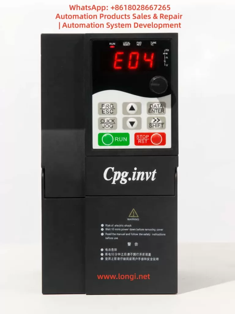
1. Overview of the E04 Fault
In Cpg.invt series variable frequency drives (VFDs), the E04 fault represents a “Constant Speed Overcurrent” condition. This fault occurs when the inverter detects that the output current exceeds the allowable threshold while the motor is already running at a stable speed (i.e., not during acceleration or deceleration).
This is a critical protection mechanism designed to prevent:
- Power device (IGBT) damage
- Motor overheating
- System instability or mechanical failure
Unlike transient overcurrent conditions, E04 indicates a sustained abnormal load or electrical condition during steady-state operation, making it particularly important to analyze correctly.
2. Internal Mechanism of E04 Fault Detection
2.1 Current Monitoring Path
The inverter continuously monitors output current through:
- Current sensors (Hall sensors or shunt resistors)
- Analog-to-digital conversion (ADC)
- DSP/MCU processing
The system compares real-time current with internally calculated limits based on:
- Motor rated current
- Control mode (V/F or vector)
- Operating conditions
2.2 Trigger Logic
The E04 fault is triggered when:
- Output frequency is stable (steady-state operation)
- Output current exceeds the protection threshold
- The overcurrent persists beyond a defined time window
3. Differentiation from Other Overcurrent Faults
| Fault Code | Operating Stage | Description |
|---|---|---|
| E01 | Startup | Overcurrent during motor start |
| E02 | Acceleration | Overcurrent during ramp-up |
| E03 | Deceleration | Overcurrent during ramp-down |
| E04 | Constant speed | Overcurrent during steady operation |
Key insight:
E04 does not result from transient dynamics, but from load or system abnormalities under stable conditions.
4. Root Cause Analysis (Engineering Classification)
4.1 Mechanical Load Issues (Most Common)
Typical scenarios:
- Bearing seizure or increased friction
- Sudden load increase
- Conveyor jam or blockage
- Pump clogging or valve closure
- Gearbox failure
Characteristics:
- System starts normally
- After running for some time, current gradually increases
- Eventually triggers E04
4.2 Motor-Related Problems
- Partial winding short circuit
- Insulation degradation (especially in humid environments)
- Mechanical drag inside motor
- Mismatch between motor and load
Diagnostic approach:
- Measure phase resistance balance
- Perform insulation test (megger)
- Run motor without load
4.3 Output Side Electrical Faults
- Cable insulation damage
- Loose terminals causing arcing
- Phase-to-ground leakage
Characteristics:
- Fault may appear immediately or randomly
- Unstable current behavior
4.4 Incorrect Parameter Settings (Critical Factor)
Key parameters affecting current protection:
- Rated motor current
- Rated voltage
- Rated frequency
- Control mode selection (V/F or vector)
Improper configuration leads to:
- Incorrect current calculation
- False triggering of protection
- Poor control performance
4.5 Acceleration/Deceleration Time Too Short
If ramp time is too short:
- High inertia loads behave like shock loads
- Even at near-constant speed, current spikes occur
- System may misinterpret as steady-state overcurrent
4.6 Power Supply Issues
- Voltage fluctuation
- Phase imbalance or phase loss
- Harmonic distortion
Indicators:
- Multiple devices affected simultaneously
- No consistent load-related pattern
4.7 Inverter Hardware Fault
Possible failures:
- IGBT degradation or partial failure
- Current sensing circuit malfunction
- Gate driver issues
Characteristics:
- Fault persists even without load
- May be accompanied by abnormal noise or heat
5. Systematic Troubleshooting Procedure
Step 1: Confirm Fault Timing
- Occurs during startup → not E04
- Occurs during steady operation → E04 confirmed
Step 2: Run Motor Without Mechanical Load
Procedure:
- Disconnect mechanical load
- Run motor freely
Result interpretation:
| Result | Conclusion |
|---|---|
| Normal | Mechanical problem |
| Fault persists | Electrical or drive issue |
Step 3: Check Motor Condition
- Measure three-phase resistance balance
- Perform insulation resistance test
- Replace with known-good motor for comparison
Step 4: Inspect Output Circuit
- Check U/V/W wiring integrity
- Inspect cable insulation
- Verify no grounding faults
Step 5: Verify Parameter Settings
Focus on:
- Motor rated current
- Control mode
- Parameter consistency
Recommended approach:
- Restore factory settings
- Reconfigure parameters from motor nameplate
- Perform auto-tuning
Step 6: Adjust Acceleration/Deceleration Time
Recommendations:
- Increase acceleration time (especially for heavy loads)
- Ensure smooth torque transition
Step 7: Monitor Real-Time Current
Observe inverter display:
- Check current value during operation
- Compare with rated current
Step 8: Evaluate Inverter Hardware
If all above steps fail:
- Suspect power module (IGBT)
- Check current sensing circuit
- Consider board-level repair or replacement
6. Engineering Conclusions
- Over 80% of E04 faults originate from mechanical load problems
- Incorrect parameter configuration is the second most common cause
- Output-side grounding faults are often hidden but critical
- Hardware failures are less frequent but must be considered
7. Preventive Measures
7.1 Proper Parameter Configuration
- Always input motor nameplate data accurately
- Perform auto-tuning before operation
7.2 Optimize Ramp Time
- Use longer acceleration time for high-inertia loads
- Avoid abrupt torque changes
7.3 Regular Maintenance
- Inspect mechanical system regularly
- Check cable insulation condition
7.4 Improve Power Quality
- Install filters if necessary
- Ensure stable and balanced supply
8. Final Insight
The E04 “Constant Speed Overcurrent” fault is not simply an indication of high current. It reflects a deeper issue:
The system is unable to maintain stable operation under existing load or electrical conditions.
Effective resolution requires a structured approach:
Mechanical → Motor → Parameters → Electrical → Drive Hardware
Only by following this hierarchy can the root cause be accurately identified and permanently eliminated.