Posted on

Panasonic MCDJT3220 Servo Drive Alarm 49.0: Model Identification, Encoder Fault Analysis, and Practical Troubleshooting Guide

In industrial automation maintenance, it is very common for a customer to send only a servo drive nameplate photo or a short alarm video and ask the technician to identify the model, determine the series, and analyze the fault. For experienced servo technicians, the nameplate and alarm code often provide enough key information to establish the initial diagnostic direction. However, for non-specialists, different Panasonic servo drive series can look similar from the outside, and model names can easily be confused. As a result, MINAS LIQI, A4, A5, and A6 series drives are sometimes misidentified.

This article is based on a real field case involving a Panasonic AC Servo Driver. The nameplate shows the model as MCDJT3220, and the video appears to show the display flashing 49.0. Based on the nameplate, Panasonic servo model naming, and common field repair experience, this drive should not be identified as a MINAS A5 or MINAS A6 unit. It is a Panasonic MINAS LIQI series servo drive. The displayed alarm 49.0 should not first lead the technician toward the IGBT module, main power circuit, or motor U/V/W output stage. Instead, the main diagnostic direction should be the servo motor encoder feedback chain, especially the encoder itself, encoder cable, X2 encoder connector, and the encoder receiving circuit inside the drive.


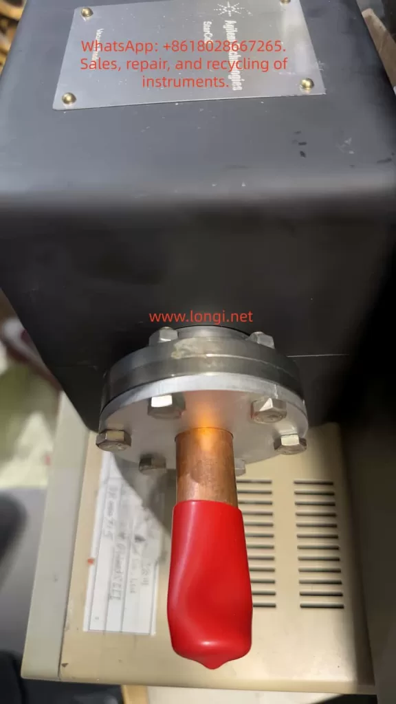
1. Nameplate Identification: This Is Not an A5 or A6 Drive, but a LIQI Series Drive

From the customer’s photo, several important details can be read from the drive nameplate:

  • Brand: Panasonic
  • Product type: AC Servo Driver
  • Model: MCDJT3220
  • Input power supply: 220–240V AC
  • Input phase: single phase
  • Output: 0–240V, three phase
  • Output current: 4.0A
  • Power rating: 750W

The most important information is the model number: MCDJT3220. This model belongs to the Panasonic MINAS LIQI series, not the MINAS A5 or MINAS A6 series.

Many maintenance technicians immediately think of Panasonic A4, A5, or A6 servo drives when they see a Panasonic servo unit, because these series are widely used in factory automation, packaging machines, CNC equipment, labeling machines, printing machines, and various motion control systems. However, Panasonic also has the LIQI series, which is generally positioned as an economical servo system for relatively simple positioning, speed control, light-load transmission, packaging machinery, small automation equipment, and similar applications.

From the model naming structure, MCDJT3220 is clearly different from common A5 or A6 model formats. Panasonic A5 and A6 drives often use model structures such as MBDHT, MCDHT, MADHT, or MDDHT. The LIQI series commonly uses model combinations such as MCDJT. Therefore, the nameplate alone is already sufficient to make a reliable identification: this is a Panasonic MINAS LIQI 750W servo drive.

This distinction is important for repair quotation, spare parts procurement, and technical diagnosis. Different Panasonic servo series may use different control interfaces, encoder protocols, motor matching rules, parameter software, and alarm definitions. If the drive is incorrectly treated as an A5 or A6 model, the technician may consult the wrong manual, select the wrong motor, misunderstand the alarm code, or follow an incorrect troubleshooting path.


2. Basic Electrical Parameters of the Panasonic MCDJT3220

Based on the nameplate, the main electrical specifications of this MCDJT3220 servo drive can be summarized as follows:

ItemSpecification
BrandPanasonic
Product typeAC Servo Driver
SeriesMINAS LIQI
ModelMCDJT3220
Input powerSingle-phase AC 220–240V
Input frequency50/60Hz
Input current6.6A
Output voltageThree-phase 0–240V
Output current4.0A
Rated power750W
Matching motorPanasonic LIQI series servo motor

This is a 750W servo drive with single-phase 220V-class input and three-phase output for a servo motor. A common misunderstanding should be avoided here: although the input power is single phase, the output to the motor is still three-phase U/V/W. Inside the servo drive, the AC input is first rectified into a DC bus, and then the inverter stage generates three-phase PWM output for the servo motor.

Therefore, this drive should not be treated as a simple single-phase motor controller. It should also not be considered equivalent to an ordinary VFD. A servo system has not only a main power circuit and motor U/V/W output, but also a very important encoder feedback loop. If the encoder feedback is abnormal, the servo drive cannot operate normally even if the main power section is still healthy.


3. Alarm 49.0 Indicates the Encoder Feedback System Should Be the Primary Focus

In the customer’s video, the servo drive display appears to flash 49.0. According to Panasonic servo alarm logic, alarm 49.0 is generally related to encoder protection and is commonly described as:

Incremental Encoder CS Signal Error Protection

In practical terms, it can be understood as:

Incremental encoder CS signal error
or, more simply:

The encoder feedback signal is abnormal, and the servo drive cannot correctly read or identify the motor encoder feedback.

The key word here is encoder. The defining characteristic of a servo system is closed-loop control. The drive does not simply output voltage and current to the motor; it must also continuously receive feedback from the motor encoder to determine rotor position, speed, and direction. If the encoder feedback is incorrect, missing, unstable, or logically inconsistent, the drive cannot safely control the motor.

For this reason, alarm 49.0 should not be diagnosed first as a general “motor not running,” “drive power module failure,” or “IGBT failure” problem. The first diagnostic area should be the encoder feedback chain.


4. What Does an Encoder CS Signal Error Mean?

A servo motor usually has an encoder mounted at the rear end. The encoder converts the motor shaft position, speed, direction, and related feedback information into signals that are sent back to the servo drive. The servo drive uses this feedback for position loop, speed loop, and current loop control.

A CS signal error can be understood as an abnormality in encoder serial communication or status-check logic. During power-on or operation, the drive checks whether the encoder feedback data is valid. If the drive detects abnormal encoder data, communication check errors, missing signals, or logical inconsistency, it triggers encoder protection.

In actual repair work, an encoder CS signal error does not always mean that the encoder itself is definitely damaged. It only means that the drive is receiving abnormal encoder feedback. The root cause may be located anywhere in the feedback chain, including:

  1. Broken encoder cable;
  2. Poor contact at the encoder connector;
  3. Abnormal encoder power supply;
  4. Defective encoder inside the servo motor;
  5. Oil, water, or contamination entering the motor encoder section;
  6. Poor shielding or grounding of the encoder cable, causing electrical interference;
  7. Damaged X2 encoder interface on the drive;
  8. Damaged encoder receiving circuit inside the drive;
  9. Motor and drive mismatch;
  10. Incorrect wiring or modified encoder cable pin assignment.

Therefore, when facing alarm 49.0, the correct method is not to immediately replace the drive. The technician should isolate and check the feedback path step by step: drive → encoder cable → motor encoder.


5. Common Causes of Alarm 49.0

5.1 Encoder Connector Not Fully Inserted or Poor Pin Contact

This is one of the most common and easily overlooked causes in the field. After transportation, machine vibration, drive replacement, cable removal, or maintenance work, the encoder connector may become slightly loose. It may look inserted from the outside, but the locking mechanism may not be fully engaged, or one of the internal pins may not be making reliable contact.

After long-term use, oil, dust, moisture, oxidation, or contamination may also accumulate inside the connector. Encoder signals are low-voltage weak signals. Unlike main power wiring, a small amount of contact resistance or instability can already cause communication failure.

The technician should power off the equipment, wait for the servo drive to discharge, unplug the X2 encoder connector, and inspect the pins carefully. Look for bent pins, recessed pins, broken pins, blackened contacts, oil contamination, moisture, or corrosion. After inspection and cleaning, the connector should be fully inserted and locked before powering on again.

5.2 Internal Breakage or Intermittent Contact in the Encoder Cable

Servo motor encoder cables are usually multi-core cables with thin conductors and shielding. In machines using drag chains, reciprocating axes, robotic arms, feeding mechanisms, cutting axes, or moving carriages, encoder cables are repeatedly bent during operation. Over time, one or more internal conductors may break.

The difficult part is that the outer sheath may still look normal while an internal conductor is already cracked or intermittently open. The machine may work when stationary but alarm when the axis moves to a certain position. The alarm may also appear or disappear when the cable is lightly moved.

For this type of fault, visual inspection alone is not reliable. A multimeter can be used to check continuity pin by pin. During the continuity test, gently bend and move the cable, especially near the motor end, drag chain bending section, and connector root. If the resistance changes or the continuity jumps, the cable likely has an internal break or intermittent connection.

5.3 Abnormal Encoder Power Supply

The encoder normally requires a low-voltage supply from the servo drive, commonly 5V or another specified voltage depending on the system. If the encoder power supply is missing or pulled down, the drive cannot read encoder data correctly.

There are two typical types of encoder power supply problems.

The first type is that the drive does not output the encoder supply correctly. Possible internal causes include a damaged 5V supply circuit, protective resistor, regulator, fuse element, or related power component.

The second type is that the external encoder cable or encoder itself is shorted, pulling down the encoder power supply from the drive. In this case, if the technician replaces only the drive without identifying the external short, the replacement drive may still show the same alarm or may even suffer damage again.

During repair, the technician may disconnect the encoder cable and check whether the encoder supply voltage from the drive side returns to normal. Another effective method is to connect the drive to a known-good matching motor and encoder cable for comparison testing. When measuring the encoder connector, extreme care is required to avoid shorting adjacent pins with the meter probe. A megohmmeter or insulation tester must never be used on encoder signal lines, because the high test voltage can easily damage the encoder and the drive input circuit.

5.4 Defective Motor Encoder

If the encoder connector and cable are confirmed to be normal but alarm 49.0 remains, the motor encoder itself must be suspected. Servo motor encoder damage can be caused by many factors, including:

  • Water entering the motor;
  • Oil entering the encoder section;
  • Mechanical impact on the motor rear cover;
  • Aging of encoder electronic components;
  • Heavy dust contamination;
  • Poor shielding or grounding causing static discharge or interference damage;
  • Hot-plugging the encoder cable;
  • Long-term high-temperature operation causing encoder aging.

A defective encoder may cause an alarm immediately at power-on, or it may fail only after the motor warms up. A temperature-dependent encoder fault can be especially difficult to identify because the drive may work normally when cold and fail only after some operating time.

5.5 Motor and Drive Mismatch

A servo drive cannot be connected to any motor simply because the power rating appears similar. Different Panasonic servo series may use different encoder protocols, feedback resolution, signal formats, and motor identification logic. If the customer has replaced the motor, drive, or cable, it is essential to confirm that the motor model is compatible with the MCDJT3220 drive.

In field repair, this type of situation is very common. The original drive may have failed, and the customer may have found another drive with the “same power rating” as a replacement. Or the original motor may have been replaced by another motor with a similar appearance. For an ordinary VFD driving a three-phase induction motor, similar voltage and power ratings may sometimes be enough for a basic test. However, a servo system is different. If the encoder protocol or motor identification is not compatible, the drive may immediately alarm and refuse to run.

Therefore, when diagnosing alarm 49.0, the motor nameplate must also be checked. The technician should confirm the motor model, encoder type, and power rating, and verify that the motor is suitable for the MCDJT3220 LIQI drive.

5.6 Fault in the Drive’s Internal Encoder Interface Circuit

If a known-good matching motor and encoder cable are connected to the drive and alarm 49.0 still appears, then the internal encoder interface circuit of the drive becomes the main suspect.

The encoder interface circuit may include:

  • Encoder power supply circuit;
  • Input protection components;
  • Differential receiver or serial communication interface IC;
  • Pull-up and pull-down resistors;
  • Filtering capacitors;
  • Optocouplers or isolation components;
  • MCU or control-chip input section.

This part of the circuit is a weak-signal processing circuit and can be damaged by external short circuits, hot-plugging, incorrect encoder wiring, electrostatic discharge, water corrosion, or contamination. Once the encoder interface circuit is damaged, the main power stage of the servo drive may still be normal, but the drive will still alarm because it cannot read the motor feedback.

In such a case, the technician should not focus only on measuring the IGBT or the DC bus voltage. For alarm 49.0, the diagnostic focus should be the X2 encoder interface and its related receiving circuit.


6. Recommended Field Troubleshooting Procedure

When dealing with this alarm, it is best to follow a structured troubleshooting procedure instead of immediately disassembling the drive or replacing expensive components.

Step 1: Confirm That the Alarm Code Is Really 49.0

First, observe the display carefully and confirm that the code is indeed 49.0, not 4.9, 49, E49, or another similar-looking code. Some servo drive displays are small, and a flashing video can easily lead to misreading. Ask the customer to take a clear still photo or record a close-up video of the display.

Correct alarm identification is critical because different alarm codes lead to completely different diagnostic paths. Overvoltage, overcurrent, undervoltage, overload, encoder fault, and excessive position deviation are all different types of faults.

Step 2: Confirm the Drive Model and Motor Model

Check the drive nameplate and confirm that the model is MCDJT3220. Then ask the customer to provide a clear photo of the servo motor nameplate. Confirm whether the motor belongs to the correct Panasonic LIQI matching series.

If the motor model cannot be confirmed, the diagnosis remains incomplete. This is especially important if the customer has replaced the motor or drive before the alarm appeared.

Step 3: Power Off and Reinsert the X2 Encoder Connector

Turn off the main power and wait until the internal capacitors of the servo drive have discharged. Then unplug the X2 encoder connector. Inspect the connector and socket carefully for abnormal pins, contamination, corrosion, loose contact, or mechanical damage. After cleaning and inspection, reinsert the connector firmly and power on again to check whether the alarm disappears.

Servo drives contain a high-voltage DC bus internally. Do not touch the terminals immediately after power-off. Always wait for proper discharge time and follow safety procedures.

Step 4: Inspect the Encoder Cable

Check the encoder cable for visible damage, cuts, crushing, pulling, oil contamination, or water ingress. If the machine uses a drag chain, pay special attention to the bending section. If the alarm changes when the cable is gently moved, an intermittent cable fault is very likely.

If possible, the fastest method is to replace the encoder cable with a known-good cable of the same type.

Step 5: Perform Cross Testing

Cross testing is one of the most effective methods in servo repair.

If there is another identical machine or compatible servo system on site, connect the suspected drive to a known-good motor and encoder cable. Alternatively, connect a known-good drive to the original motor and encoder cable.

The judgment logic is as follows:

  • If the fault follows the motor and encoder cable, the motor encoder or cable is faulty;
  • If the fault follows the drive, the drive’s internal encoder interface is faulty;
  • If replacing the encoder cable solves the problem, the encoder cable is faulty;
  • If replacing the motor solves the problem, the motor encoder is faulty;
  • If replacing the drive solves the problem, the drive interface circuit is faulty.

Cross testing is more reliable than simple measurement because encoder signals are high-speed or serial weak signals. Some problems cannot be clearly detected with a standard multimeter.

Step 6: Measure the Encoder Power Supply

If the technician has proper electrical repair experience, the encoder supply voltage can be measured. If the encoder supply voltage is abnormally low, disconnect the encoder cable and measure again.

If the supply voltage returns to normal after disconnecting the encoder cable, the external cable or motor encoder may be shorted. If the supply voltage is still missing after the encoder cable is disconnected, the drive’s internal encoder power supply circuit may be faulty.

When measuring the encoder connector, avoid shorting the pins. Do not use a high-voltage insulation tester on encoder lines.

Step 7: Check Shielding, Grounding, and Interference

If the alarm does not appear immediately at power-on but occurs intermittently during operation, the technician should also consider electrical interference. In a servo system, the U/V/W motor power cable is a strong noise source, while the encoder cable carries weak feedback signals. These two cables should not be routed closely in parallel over a long distance.

The encoder cable should be an original or high-quality shielded cable, and the shielding should be grounded according to proper practice. If the customer has extended the encoder cable, replaced it with an ordinary multi-core cable, or routed it near power wiring, the probability of alarm 49.0 increases significantly.


7. Difference Between Alarm 49.0 and Main Power Circuit Faults

Many customers see a servo drive alarm and immediately assume that the drive is damaged or that the power module has failed. However, from a repair perspective, it is necessary to distinguish the type of alarm.

If the problem is related to the IGBT module, output short circuit, overcurrent, DC bus overvoltage, braking circuit, or current detection circuit, the alarm code will usually point toward the power circuit or current feedback circuit. Alarm 49.0, on the other hand, points toward encoder feedback. In many cases, the drive may not even begin high-power output before the alarm is generated during power-on self-check or before servo enable.

In other words, alarm 49.0 does not primarily indicate:

  • IGBT failure;
  • Motor winding short circuit;
  • Braking resistor failure;
  • Main capacitor failure;
  • Rectifier bridge failure.

These parts are not impossible to fail, but based on the alarm logic, they should not be the first diagnostic priority. The encoder feedback system should be checked first. Starting with IGBT removal or main circuit testing may waste time and may not address the real fault.


8. Diagnostic Priorities Based on Different Symptoms

8.1 Alarm 49.0 Appears Immediately at Power-On

If the drive displays 49.0 immediately after power-on, before running or servo enable, the most likely causes include:

  • Encoder connector not properly inserted;
  • Broken encoder cable;
  • Encoder supply voltage shorted or missing;
  • Defective motor encoder;
  • Motor and drive mismatch;
  • Damaged encoder interface circuit inside the drive.

This type of fault is usually stable and can often be located by connector inspection, cable replacement, and cross testing.

8.2 Alarm 49.0 Appears After Servo Enable

If the drive powers on normally but alarms after servo enable, the technician should consider encoder data reading, motor identification, feedback validity, and parameter compatibility. Possible causes include:

  • Poor encoder signal quality;
  • Motor and drive parameter mismatch;
  • Partial failure in the encoder signal channels;
  • Failure when the drive attempts to read motor feedback data.

8.3 Alarm 49.0 Appears After Running for Some Time

If the equipment can run but alarms after some operating time, the main suspects are:

  • Intermittent break inside a drag-chain cable;
  • Motor encoder failure after heating;
  • Vibration causing momentary connector contact loss;
  • Encoder cable interference from nearby power wiring;
  • Cable tension when the axis moves to a certain position.

This type of fault is best diagnosed dynamically. Run the axis at low speed while observing the cable bending sections, or move the axis position and gently move the cable while watching whether the alarm appears or clears.


9. Safety Precautions During Repair

Servo drive repair involves both high-voltage power circuits and low-voltage signal circuits. The drive has 220V AC input and an internal high-voltage DC bus. The following precautions are essential:

First, do not touch main circuit terminals immediately after power-off. The internal capacitors need time to discharge.

Second, do not hot-plug the encoder cable. The encoder interface is a weak-signal electronic interface. Hot-plugging may generate transient voltage spikes and damage either the encoder or the drive interface IC.

Third, do not use a megohmmeter on encoder lines. An insulation tester is suitable for checking motor winding insulation to ground, but not for encoder signal wires. Encoder wires are connected directly to electronic circuits, and high test voltage can destroy them.

Fourth, do not randomly modify the encoder cable pinout. Servo encoder wiring is not ordinary control wiring. Pin assignment, shielding, twisted pairs, and grounding all matter. Incorrect modification may cause alarms or damage the interface circuit.

Fifth, when measuring the encoder connector, prevent probe slips and pin short circuits. Encoder connector pins are often dense. A brief short between 5V, signal, and ground pins may create a new fault.


10. Repair Communication and Quotation Suggestions

For a repair service provider, it is not professional to simply tell the customer “the drive is bad” or “the motor is bad” when alarm 49.0 appears. A better explanation is that the current alarm points to the encoder feedback chain, and further testing is required to locate the exact faulty part.

A suitable communication process is:

  1. Confirm the drive model and alarm code;
  2. Explain that the drive is a LIQI series unit, not an A5 or A6 drive;
  3. Explain that alarm 49.0 is an encoder feedback signal fault;
  4. Ask the customer for the motor nameplate, encoder cable photos, and X2 connector photos;
  5. Ask the customer to reinsert the encoder connector and inspect the cable;
  6. If possible, perform cross testing with a known-good matching motor, cable, or drive;
  7. Determine whether the fault is in the motor encoder, encoder cable, or drive interface circuit.

This approach is more professional and helps avoid misunderstanding. In particular, if the customer sends only the drive for repair but keeps the motor and encoder cable on site, the repair provider should explain that if the real fault is in the motor encoder or cable, repairing the drive alone will not solve the on-site alarm.


11. Information the Customer Should Provide

To improve diagnostic accuracy, the customer should provide the following information:

  • Full front photo of the servo drive;
  • Clear drive nameplate photo;
  • Servo motor nameplate photo;
  • Close-up photo of the X2 encoder connector;
  • Photos of both ends of the encoder cable;
  • Power-on alarm video;
  • Whether the alarm appears immediately at power-on, after servo enable, or during operation;
  • Whether the drive, motor, or cable has been replaced before;
  • Whether the machine has experienced water ingress, oil contamination, impact, cable damage, or drag-chain failure;
  • Whether there is another identical machine available for cross testing.

The more complete the information, the more accurate the fault judgment will be.


12. Conclusion

The Panasonic MCDJT3220 is a MINAS LIQI series 750W AC servo drive with single-phase 220–240V input and three-phase 0–240V output. It is not a MINAS A5 or MINAS A6 drive. The customer’s video appears to show alarm 49.0, which should be understood as an encoder feedback abnormality, commonly related to incremental encoder CS signal error protection.

The troubleshooting focus should not begin with the IGBT, rectifier bridge, braking resistor, or main capacitor. Instead, it should focus on the following chain:

Drive X2 encoder interface → encoder cable → motor encoder → encoder power supply and receiving circuit.

In practical repair work, the most effective method is to inspect the connector and cable first, then perform cross testing among the drive, encoder cable, and motor. If the alarm disappears after connecting a known-good matching motor and encoder cable, the original motor encoder or cable is faulty. If the alarm remains, the drive’s internal encoder interface circuit is likely damaged.

For technicians and service engineers, the key point is this: when alarm 49.0 appears on this Panasonic servo drive, do not immediately assume that the power module is defective. A servo system is a closed-loop control system, and encoder feedback is the foundation of operation. If the encoder feedback is invalid, the drive will protect itself even when the main power circuit is still normal. Correct model identification, accurate alarm interpretation, and systematic feedback-chain troubleshooting are the most important steps for solving this type of Panasonic servo fault.

Posted on

MARPOSS TBD Laser Tool Breakage Detector Repair and Signal Testing: From Wiring Identification to Tool OK Output Diagnosis

1. Overview: The TBD Is Not a Conventional Laser Tool Setter

The MARPOSS TBD is a non-contact laser tool breakage detector used on CNC machining centers, drilling/tapping machines, and automated machine tools. At first glance, many technicians may mistake it for a normal laser tool setter. This leads to a common misunderstanding: as long as an object blocks the laser beam, the output should change immediately.

That is not how this device works.

The TBD is not primarily designed to measure tool length or automatically write tool offset values into the CNC system. Its core function is to check whether a tool is present, broken, or still suitable for machining. A more accurate description would be:

MARPOSS TBD laser tool breakage detector / non-contact tool presence detector.

During operation, the CNC or PLC enables the TBD through an external input signal. The spindle moves the tool to a preset inspection position. The TBD emits a laser beam toward the tool surface. If the tool is intact, the laser is reflected back to the receiver lens. If the tool is broken, the expected reflective surface is missing, and the detector will classify the tool as broken or not identified.

Therefore, the TBD should not be treated as a simple through-beam or reflective photoelectric switch. It does not merely detect whether something blocks the laser beam. It must receive a valid reflected signal that matches its internal recognition logic. Only after the controller identifies a valid tool condition will the STATUS indicator turn on and the Tool OK output become active.

This distinction is crucial for repair work. If the technician only blocks the laser with a finger or metal plate and expects the output to change, the test result may be misleading.


MARPOSS TBD reflective laser tool breakage detector installed inside a CNC machine, emitting and receiving a red laser beam from a rotating cutting tool for non-contact tool presence detection.

2. External Structure and Key Components

A typical MARPOSS TBD unit has several important physical features.

The first is the large circular optical window on the front. This is mainly the receiving window. Reflected laser light from the tool surface enters through this lens and is detected by the internal optical receiver. Behind this window are typically the receiving optics, photodiode circuit, preamplifier, and signal conditioning circuits. If this window is cracked, fogged, contaminated, or filled with coolant residue, the detector may fail to identify the tool even when the laser emitter is working.

The second feature is the small laser emission aperture. The laser beam is emitted from this small opening and aimed toward the tool. The reflected light then returns to the large receiving lens. In many units, an air purge port is also provided near the optical area. The purpose of the air port is to keep coolant mist, oil, dust, and chips away from the optical surfaces.

The third feature is the multi-pin circular connector. This connector carries the power supply, Laser Enable input, Tool OK output, Signal Monitor analog output, and related common terminals. Different TBD versions and cable assemblies may use different wiring colors. Therefore, wiring should not be identified only by wire color. It must be confirmed by PCB tracing, component function, and actual testing.

The fourth feature is the front indicator panel. It usually has three indicators:

  • POWER
  • SIGNAL
  • STATUS

POWER indicates the power and laser enable state. SIGNAL indicates reflected signal strength. STATUS indicates whether the tool has been successfully identified. In troubleshooting, STATUS is the most important indicator for judging whether the Tool OK output should be active.

The fifth feature is the FOCUS POSITION adjustment. On some versions, this appears as a small adjustment mechanism marked with “FOCUS POSITION” and “FAR.” This is not a general operating mode selector. It is related to optical focus or detection distance. If the distance, angle, or focus setting is incorrect, the detector may show analog signal variation while the STATUS indicator remains off.


Technician testing an opened MARPOSS TBD laser tool breakage detector on a repair bench, measuring the PCB, signal wiring, laser enable input, signal monitor, and Tool OK output with a multimeter.

3. Identifying the Six Signal Wires

During repair, the unit may contain a separate pair of main power wires and a six-wire signal harness connected to the circular connector. By comparing a faulty unit with a known-good TBD, the six signal wires can be identified as follows:

Wire ColorProbable FunctionDescription
BlackSignal Monitor reference groundAnalog reference, not necessarily connected to main power 0V
RedSignal Monitor analog output0–5V analog monitor signal
YellowTool OK / COM OUT terminalOne side of PVT212S output
GreenTool OK / COM OUT terminalThe other side of PVT212S output
PinkLaser Enable inputExternal enable input
GrayCOM INCommon terminal for Laser Enable input

Several important points must be emphasized.

First, the black wire may connect to a local capacitor negative terminal or local signal reference node on the PCB, but it is not necessarily connected to the main power supply negative terminal. It should not be assumed to be the same as the device power 0V.

Second, the red wire is not the Laser Enable wire. PCB tracing shows that the red wire passes through a resistor and enters an AD823A signal conditioning stage. This strongly suggests that it belongs to an analog signal path, most likely the Signal Monitor output. Applying 12V or 24V to the red wire may damage the analog front end.

Third, the pink and gray wires form the Laser Enable input pair. In actual testing, applying an external 12V signal through a 4.7kΩ resistor to the pink wire, with the gray wire connected to 0V, caused the POWER indicator to change from green to orange and the laser to turn on. This confirms the pink/gray pair as the enable input.

Fourth, the yellow and green wires connect to the output side of a PVT212S PhotoMOS relay. They are not active voltage outputs. They behave like an isolated solid-state contact. An external power source and load are required to observe switching behavior.


Technical diagram explaining the MARPOSS TBD reflective laser tool detection principle, showing laser emission, reflected light reception, signal monitor output, status recognition, and Tool OK output flow.

4. The Role of the PVT212S PhotoMOS Relay

The PCB contains a PVT212S device. This component is not a simple optocoupler and not an analog amplifier. It is a PhotoMOS solid-state relay. Internally, it contains an input LED and an output MOSFET switch, optically isolated from each other.

In the TBD, the PVT212S is used as the final isolated Tool OK output stage.

Its working logic can be understood as follows:

The controller determines that a valid tool has been identified
↓
The controller drives the input LED of the PVT212S
↓
The PVT212S output MOSFET turns on
↓
The yellow and green wires form a closed solid-state switch
↓
The CNC / PLC receives the Tool OK signal

This explains why the yellow and green wires do not output 12V or 24V by themselves. They are equivalent to an isolated relay contact. Measuring yellow-to-ground or green-to-ground with a multimeter may show no meaningful voltage.

The correct way to test this output is to create an external low-current load circuit, for example:

+12V → 2.2kΩ or 4.7kΩ resistor → LED → Yellow wire
Green wire → 0V

If there is no response, reverse the yellow and green wiring and test again. In many PhotoMOS outputs, polarity may not matter for low-current DC tests, but both directions should still be verified.

However, the PVT212S output will only switch if its input side is driven. If pins 1 and 2 of the PVT212S always measure 0V, the yellow/green output will not change no matter how the external output circuit is connected.


5. Why Blocking the Laser Does Not Necessarily Activate the Output

A common mistake is to block the laser beam with a hand or metal plate and expect the Tool OK output to change. This is not a valid test for a TBD.

The TBD is based on reflected laser detection. It is not checking simple beam interruption. It is looking for reflected light from a tool surface under the correct geometric and optical conditions.

When a hand blocks the laser, the red/black Signal Monitor output may change significantly. For example, it may rise from about 0.6V to around 5V. This only proves that the receiver and analog signal chain respond to optical changes. It does not prove that the controller has recognized a valid tool.

A hand, flat metal plate, or random obstruction may create a saturated or invalid reflection. The internal logic may classify this as an invalid condition rather than a valid tool.

A more realistic test should use:

  • A drill bit
  • A tap
  • A shiny round steel rod
  • A screwdriver shaft
  • A cylindrical metal tool

The laser should strike the cylindrical surface or tool surface, not simply a flat plate. The best simulation is to rotate the tool or round bar slowly, because the real application typically involves rotating tools.

Only when the controller decides that the reflected signal corresponds to a valid tool will the STATUS indicator turn on. Only then should the PVT212S input and yellow/green output be expected to change.


6. Meaning of the POWER, SIGNAL, and STATUS Indicators

The three front indicators are essential for diagnosing the TBD.

POWER Indicator

The POWER indicator shows the power and laser enable state.

A typical operating sequence is:

  • Main power only: POWER should be green.
  • Laser Enable active: POWER should change to orange.
  • Fault state: POWER may show red or fail to remain on.

If the unit cannot hold a green POWER indicator with only main power applied, it has not entered normal standby. In that case, there is no point in expecting the yellow/green output to switch. The internal power supply, control logic, reset circuit, laser driver, or local regulators must be checked first.

SIGNAL Indicator

The SIGNAL indicator reflects the strength or quality of the received optical signal. It does not directly mean that the Tool OK output is active.

Signal Monitor voltage and the SIGNAL indicator are useful for aligning the optical path. However, signal variation alone does not guarantee that the tool has been identified.

STATUS Indicator

STATUS is the key indicator.

When STATUS turns on, the unit has identified the tool. When STATUS remains off, the tool is not identified or is considered broken. As long as STATUS is off, the PVT212S output may remain inactive. This is normal behavior.

If STATUS turns on but PVT212S pins 1 and 2 still remain at 0V, then the output drive circuit should be investigated.


7. The Red and Black Signal Monitor Wires

The red and black wires form the analog Signal Monitor output.

In testing, the voltage between red and black may vary from roughly 0V to 5V depending on the reflected signal. For example:

  • No valid reflection: around 0.6V
  • Strong obstruction or saturated reflection: near 5V

This signal is useful for optical alignment and signal evaluation. It is not a switching output and not a Laser Enable input.

The correct use of the Signal Monitor is:

  1. Apply the Laser Enable signal through the pink/gray pair.
  2. Measure DC voltage between the red and black wires.
  3. Move a drill bit or round rod in the laser path.
  4. Observe voltage changes.
  5. Use the voltage together with SIGNAL and STATUS indicators to find a valid detection position.

If red/black voltage changes but STATUS remains off, the receiver circuit is responding, but the signal is not being accepted as a valid tool identification condition.


8. The Importance of FOCUS POSITION Adjustment

The TBD is highly sensitive to distance, angle, and focus. The FOCUS POSITION adjustment is critical.

The unit may output laser light and show analog signal variation, but still fail to identify the tool if the focus is not correct. Typical symptoms include:

  • POWER changes from green to orange after Laser Enable.
  • The laser is visible.
  • Red/black Signal Monitor voltage changes.
  • SIGNAL may change.
  • STATUS remains off.
  • PVT212S is not driven.
  • Yellow/green output does not change.

This does not necessarily mean the electronics are faulty. It may simply mean the optical geometry is wrong.

A proper bench test should use a fixed setup. The TBD should be clamped securely. The test drill or round rod should also be fixed in a stable holder. Suggested starting distances are:

300mm → 500mm → 800mm

At each distance, slowly adjust:

  • Tool height
  • Tool angle
  • Lateral position
  • FOCUS POSITION
  • Tool rotation

The goal is to make STATUS turn on stably. If the technician holds the detector and tool by hand, the position may be too unstable, and STATUS may appear only briefly or not at all.


9. Function of the Air Port

The air port is often misunderstood. It is not usually an electrical interlock.

Its purpose is to provide air purge for the optical windows. It prevents coolant mist, oil vapor, dust, and chips from sticking to the transmitter aperture and receiver lens.

The air purge helps with:

  • Keeping the laser emission aperture clean
  • Keeping the receiver window clean
  • Reducing coolant interference
  • Improving long-term stability
  • Preventing false alarms in machine environments

For bench testing, air supply is generally not required to verify main power, Laser Enable, laser output, Signal Monitor, STATUS, and Tool OK output. However, for actual machine operation, clean and dry compressed air should be used. If the air contains oil or water, it may make the optical window dirtier rather than cleaner.


10. Complete Test Procedure Using a Known-Good Unit

The most efficient troubleshooting method is to compare the faulty unit with a known-good TBD.

Step 1: Main Power Test

Apply main power only.

Expected result:

  • POWER indicator stays green.
  • No abnormal heating.
  • The main controller appears to start normally.

If the POWER indicator does not stay green, check internal power supply, local regulators, reset circuit, MCU power, and laser driver supply.

Step 2: Laser Enable Test

Apply the enable signal:

+12V or +24V → 4.7kΩ resistor → Pink wire
0V → Gray wire

Expected result:

  • POWER changes from green to orange.
  • Laser output becomes active.

This confirms the pink/gray pair as Laser Enable and COM IN.

Step 3: Signal Monitor Test

Measure between red and black:

Red probe → Red wire
Black probe → Black wire

Move a drill bit or round metal rod in front of the laser. The voltage should change in the 0–5V range.

Step 4: STATUS Recognition Test

Use a drill bit, tap, or round steel rod to simulate a tool. Adjust distance, angle, rotation, and FOCUS POSITION until STATUS turns on.

This is the key step. Without STATUS, the Tool OK output should not be expected to switch.

Step 5: PVT212S Input Test

When STATUS is on, measure the DC voltage directly across PVT212S pins 1 and 2.

If the controller is driving the output, the input side should show a forward LED drive voltage.

If STATUS is on but pins 1 and 2 remain at 0V, check the PVT drive circuit.

Step 6: Yellow/Green Output Test

Build a low-current external test circuit:

+12V → 4.7kΩ resistor → LED → Yellow wire
Green wire → 0V

If there is no response, reverse yellow and green. Observe whether the LED changes when STATUS turns on and off.


11. Troubleshooting a Faulty TBD Unit

When a faulty TBD has a cracked lens, coolant ingress, corrosion, or unstable output, the repair should proceed stage by stage.

Case 1: POWER Does Not Stay Green

If the unit cannot remain in green standby with only main power applied, check:

  • Main power input
  • Power driver daughterboard
  • 5V and 3.3V regulators
  • MCU reset
  • Clock circuit
  • Laser driver detection
  • Corrosion leakage
  • Protection devices

At this stage, Tool OK output testing is not meaningful.

Case 2: POWER Is Green, but Laser Enable Does Not Turn It Orange

Check:

  • Pink/gray input circuit
  • Input current limiting resistor
  • Input optocoupler or isolation device
  • Input protection diodes
  • COM IN reference circuit
  • MCU input recognition

Case 3: POWER Turns Orange, but There Is No Laser

Check:

  • Laser diode
  • Laser driver
  • Laser module cable
  • Laser aperture contamination
  • Driver daughterboard
  • Laser fault detection circuit

Case 4: Laser Works, but Red/Black Signal Monitor Does Not Change

Check:

  • Receiver window
  • Photodiode
  • Transimpedance preamplifier
  • AD823A signal conditioning circuit
  • Lens contamination
  • Optical alignment

Case 5: Signal Monitor Changes, but STATUS Never Turns On

Check:

  • Detection distance
  • FOCUS POSITION
  • Tool surface
  • Tool rotation
  • Signal saturation or insufficient signal
  • Receiver window fogging
  • Controller recognition logic

Case 6: STATUS Turns On, but Yellow/Green Output Does Not Switch

Check:

  • PVT212S pins 1 and 2 drive voltage
  • PVT input resistor
  • PVT driver transistor or MOSFET
  • PVT212S device itself
  • Output protection components
  • Yellow/green cable path

12. Common Mistakes During Repair

Mistake 1: Treating Red/Black as Power Wires

Red and black belong to Signal Monitor, not main power. A low voltage between red and black is normal when there is no valid optical signal.

Mistake 2: Applying 12V to the Red Wire

The red wire is part of the analog signal chain. Applying 12V to it may damage the AD823A input stage or related analog circuitry.

Mistake 3: Expecting Yellow/Green to Output 24V

Yellow and green are isolated switch output terminals. They do not actively output voltage. An external load and supply are required.

Mistake 4: Testing with a Hand Blocking the Laser

Blocking the laser with a hand only proves that the receiver sees optical disturbance. It does not simulate a valid rotating tool.

Mistake 5: Replacing the PVT212S Before STATUS Turns On

If STATUS is not on, PVT212S may not be driven. Replacing the PhotoMOS relay without proving that the controller is issuing Tool OK may be unnecessary.

Mistake 6: Assuming the Air Port Is Required for Electrical Output

The air port is for optical cleaning and protection. It is not the main reason the Tool OK output fails to switch during bench testing.


13. Practical Recommendations for Machine Installation

When installing or repairing a MARPOSS TBD on a machine tool, several practical points should be observed.

The detector must be mounted rigidly. Any movement between the TBD and the tool detection position can cause unstable recognition.

The CNC program must move the tool to the correct inspection position. The TBD does not automatically search for the tool tip. It checks whether a valid reflective tool surface exists at the programmed location.

The tool should ideally rotate during detection. A rotating tool produces a more realistic reflective pattern than a static flat surface.

The optical windows must be kept clean. Coolant residue, oil mist, and chips can cause false broken-tool alarms.

The air purge should use clean, dry air. Dirty air may contaminate the optics instead of cleaning them.

When replacing a damaged TBD with a used unit, do not rely only on similar appearance. Confirm the code, connector, wiring, optical focus, detection distance, and output behavior.

Before returning a repaired unit to service, the technician should verify:

  • Main power
  • Laser Enable
  • Laser output
  • Signal Monitor
  • STATUS recognition
  • Tool OK output

A unit that only powers on but cannot identify a simulated tool is not properly tested.


14. Conclusion

The MARPOSS TBD laser tool breakage detector is not a simple laser switch. It is an optical tool recognition system consisting of laser emission, reflected light reception, analog signal conditioning, controller judgment, status indication, and isolated output stages.

Based on practical tracing and testing, the six signal wires can be defined as:

Black: Signal Monitor reference ground
Red: Signal Monitor 0–5V analog output
Yellow / Green: Tool OK / COM OUT isolated output
Pink: Laser Enable
Gray: COM IN

When the pink/gray enable input is activated, POWER changes from green to orange and the laser turns on. The red/black Signal Monitor voltage varies with reflected light. The yellow/green output is controlled by the PVT212S PhotoMOS relay and only changes when the detector identifies a valid tool.

The key point is this:

The PVT212S output will not operate merely because the laser is blocked. It operates only when the detector receives valid reflected tool information, the STATUS indicator confirms Tool Identified, and the controller drives the PVT212S input.

For repair technicians, this means that troubleshooting must follow the signal chain:

Main power
↓
Laser Enable
↓
Laser emission
↓
Reflected signal reception
↓
Signal Monitor
↓
STATUS recognition
↓
PVT212S drive
↓
Tool OK output

Once this logic is understood, troubleshooting becomes much more systematic. Faults such as cracked receiver glass, coolant ingress, corroded PCB areas, unstable output, no Tool OK signal, or false broken-tool alarms can be separated into optical faults, power faults, analog reception faults, controller recognition faults, or output stage faults.

This is the correct way to repair and test a MARPOSS TBD laser tool breakage detector: not by guessing from wire colors or simply blocking the laser, but by verifying each stage of the signal path step by step.

Posted on

Troubleshooting WEIHONG NK300BX CNC Controller Blue Screen: Technical Analysis of STOP 0x000000EA and iegddis Display Driver Failure

1. Fault Overview

WEIHONG CNC control systems are widely used in woodworking engraving machines, panel cutting machines, CNC routers, and woodworking machining centers. Compared with common faults related to VFDs, servo drives, PLCs, limit switches, or pneumatic components, faults inside the CNC controller itself are often more difficult for field technicians to judge correctly. Once the controller fails to start properly, the whole machine cannot perform homing, load machining programs, enable servo axes, or run automatic operation.

In this case, a woodworking machining center equipped with a WEIHONG NK300BX controller showed a Windows blue screen after power-on. The screen displayed the following message:

A problem has been detected and Windows has been shut down to prevent damage to your computer.

The most important fault information on the screen was:

STOP: 0x000000EA

and the related fault file was:

iegddis

The blue screen also showed the following explanation:

The device driver got stuck in an infinite loop. This usually indicates problem with the device itself or with the device driver programming the hardware incorrectly.

From these messages, it can be determined that this is not a normal CNC machining alarm. It is not a servo alarm, spindle inverter alarm, tool magazine alarm, air pressure alarm, limit switch alarm, or emergency stop alarm. Instead, it is a Windows system crash inside the industrial computer section of the CNC controller.

The NK300BX controller is not only a simple operation panel. It normally contains an industrial computer mainboard, system storage device, RAM, display circuit, I/O control interface, CNC control software, and dedicated machine configuration files. Therefore, this type of blue screen fault must be analyzed from the perspective of an industrial PC system, not only from the perspective of ordinary machine electrical faults.

WEIHONG NK300BX CNC controller showing a Windows blue screen error with STOP 0x000000EA and iegddis display driver fault on a woodworking machining center.

2. Difference Between an NK300BX Blue Screen and a Normal CNC Alarm

In woodworking CNC machines, technicians usually judge faults from alarm messages shown inside the CNC software interface. Typical alarms include emergency stop not released, axis limit triggered, servo not ready, spindle not started, insufficient air pressure, homing failure, tool number error, tool magazine position error, or external input abnormality. These alarms are generated after the CNC software has started normally and detected an abnormal condition from the machine.

The blue screen in this case is completely different. A Windows blue screen means that the underlying operating system has crashed. When this happens, the WEIHONG CNC software cannot continue running, the I/O status cannot be read normally, servo enable signals cannot be controlled properly, spindle control cannot be issued, machining programs cannot be loaded, and homing operation cannot be performed.

Therefore, this type of fault should not be handled as an ordinary machining alarm. Checking the limit switches, emergency stop button, servo drives, spindle VFD, pneumatic valves, air pressure switch, or tool sensor will usually not solve the problem. The correct maintenance focus should be on the internal industrial computer hardware, system disk, display driver, RAM, motherboard chipset, graphics circuit, cooling condition, and power supply stability of the controller.

3. Meaning of STOP 0x000000EA

The Windows blue screen code STOP 0x000000EA generally means that a device driver has become stuck in an infinite loop. Windows stops the system to prevent further damage or a complete lock-up. The explanation shown on the blue screen already gives an important clue: the device driver is unable to correctly control the hardware, or the hardware itself is not responding correctly.

In this specific case, the fault file shown is iegddis. This file name is generally related to the Intel integrated graphics/display driver. Many early industrial PC mainboards use Intel chipsets and integrated graphics. During Windows startup and operation, the display driver is responsible for screen output, graphical interface refresh, and communication with the display hardware.

If the display driver file is damaged, the integrated graphics chipset is abnormal, the RAM reads data incorrectly, or the system disk has damaged files, the system may report this kind of blue screen.

For a CNC controller, this type of problem may appear in different ways. Some machines may occasionally show a blue screen and work again after restart. Some may repeatedly show the blue screen and never enter the WEIHONG operation interface. Some may start normally but crash after running for a period of time due to heat, vibration, unstable power supply, or file read errors. Different symptoms point to different possible root causes.

Technician inspecting the internal motherboard, RAM module, DOM system disk, power supply, and cooling area inside a dusty WEIHONG NK300BX CNC controller cabinet.

4. Possible Causes

4.1 Damaged Windows System Files or Display Driver

This is one of the most common causes. Woodworking CNC controllers often operate in dusty environments and may experience improper shutdowns, unstable power supply, sudden power loss, or long-term lack of system maintenance. These conditions can damage Windows system files.

If the damaged file is related to the display driver, graphics initialization, or Windows startup, the machine may show STOP 0x000000EA during startup.

If the machine shows the same blue screen every time it starts, and the fault file is always iegddis, the probability of system file damage or display driver damage is high. In this situation, it is not reasonable to immediately replace servo drives or spindle inverters, because external actuators normally do not directly cause a Windows display driver blue screen.

4.2 Aging System Disk, DOM, CF Card, or Hard Disk

Many WEIHONG controllers and early industrial CNC systems use DOM electronic disks, CF cards, IDE hard disks, SATA industrial disks, or small industrial storage modules as the system storage device. After years of operation, these storage devices may develop bad sectors, slow reading speed, file corruption, missing system files, or damaged partitions.

When the system disk becomes weak, Windows may fail to read the display driver file correctly during startup. It may also read corrupted data and then crash. Common symptoms include slow startup, occasional “system not found” messages, missing file warnings, CNC software freezing, machining programs failing to save, frequent crashes, or repeated blue screens.

For CNC controller maintenance, the system disk is a very important inspection point. The system disk does not only contain Windows. It also contains the CNC software, controller card driver, machine parameters, manufacturer configuration files, tool magazine logic, I/O mapping, axis settings, and sometimes authorization files. If the system disk is completely damaged without backup, recovery becomes much more difficult.

4.3 Poor RAM Contact or Damaged RAM

Woodworking machines operate in environments with dust, vibration, temperature changes, and sometimes humidity. The RAM module inside the controller may become loose, oxidized, or contaminated with dust. Poor RAM contact can cause system files to load incorrectly, drivers to execute abnormally, and the graphical interface to crash.

RAM faults do not always produce the same blue screen code. Sometimes the machine fails during startup. Sometimes it freezes during operation. Sometimes the CNC software crashes after entering Windows. If cleaning and reseating the RAM temporarily solves the problem, poor contact is likely. If replacing the RAM completely solves the issue, the original RAM should be considered faulty.

4.4 Integrated Graphics or Motherboard Chipset Failure

Because the blue screen points to the display driver, the graphics hardware itself must also be considered. On many industrial mainboards, the graphics function is integrated into the chipset. If the graphics chipset is aging, overheating, poorly soldered, or affected by unstable power supply, the display driver may fail to control the hardware correctly, resulting in the “infinite loop” blue screen.

This possibility becomes more likely if the fault still appears after system restoration, system disk replacement, and display driver reinstallation. If the controller has been used for many years, if the cooling fan has stopped, if the heat sink is full of dust, or if motherboard capacitors are aging, the probability of motherboard hardware failure increases significantly.

4.5 Poor Cooling and Dust Contamination

The biggest environmental problem for woodworking machines is wood dust. Dust can enter the controller and accumulate on the motherboard, RAM, heat sink, power supply board, and connectors. It reduces cooling efficiency and may also cause slight leakage or corrosion when combined with moisture.

If the CPU, chipset, or graphics section overheats, the system may freeze, show a blue screen, restart automatically, or display abnormal graphics. If the customer reports that the machine works normally when cold but crashes after running for some time, or if the problem becomes more frequent in hot weather, cooling should be checked carefully.

The technician should inspect whether the internal fan is rotating, whether the heat sink is blocked by dust, and whether the motherboard is covered by wood powder.

4.6 Abnormal Controller Power Supply

Although this case mainly points to a display driver problem, the controller power supply should not be ignored. The industrial PC mainboard normally requires stable 5V, 12V, or dedicated power rails. If the power supply is aging, filter capacitors are weak, or ripple is excessive, the system may crash randomly.

A woodworking machine may contain high-interference devices such as spindle VFDs, servo drives, solenoid valves, vacuum pumps, dust collectors, and large motors. Poor grounding, weak shielding, or unstable supply voltage can increase the chance of controller instability.

For an intermittent blue screen, the technician should measure the controller input voltage and internal power supply output. It is also important to observe whether the blue screen appears when the spindle starts, when servo axes move, or when a dust collector or vacuum pump is switched on. If the fault is synchronized with high-power equipment operation, power quality and electrical interference must be investigated.

5. Initial On-Site Diagnosis

When an NK300BX controller shows a blue screen, external electrical components should not be replaced blindly. A correct diagnosis should begin with the blue screen information, timing of the fault, restart behavior, and internal controller condition.

First, record the blue screen code and the file name. In this case, the important information is STOP 0x000000EA and iegddis. This clearly points toward the Windows display driver, graphics hardware, or related system files.

Second, check whether the fault appears every time. If the controller shows the same blue screen at every startup, the system disk, display driver, system files, or motherboard graphics hardware are the main suspects. If the fault appears only occasionally, RAM contact, cooling, power supply, or vibration-related problems should also be considered.

Third, power off the machine completely and wait for several minutes before restarting. If the controller can enter Windows or the WEIHONG CNC interface even once, immediately back up machine parameters, machining programs, and configuration files. Do not continue repeated test starts without backup, because if the system disk is already weak, repeated abnormal shutdowns may make the damage worse.

Fourth, open the controller and check the internal condition. Look for heavy wood dust, stopped fans, swollen capacitors, loose RAM, loose system disk connectors, oxidized terminals, or damaged ribbon cables.

Fifth, if possible, try to enter Windows Safe Mode. If Safe Mode can be entered, the basic hardware may still be functional, and the problem may be related to the display driver or normal startup items. The display driver can be removed or replaced by the standard VGA driver for testing. However, for CNC controllers, random driver installation is not recommended, because an incorrect driver version may affect the CNC software environment or controller card driver.

6. Recommended Repair Procedure

6.1 Back Up Data First

If the controller can still enter the system, the first action should be backup, not repair. Important data includes machine parameters, machining programs, tool magazine parameters, homing parameters, I/O configuration, manufacturer-specific configuration files, WEIHONG software installation package, and license-related files if available.

For woodworking machining centers, even if the control system model is the same, the parameters may be different from one machine to another. Machine stroke, pulse equivalent, home direction, limit polarity, tool magazine logic, vacuum zone control, spindle command method, lubrication output, and pneumatic sequence may all be customized by the machine manufacturer.

If the system disk is damaged and there is no parameter backup, reinstalling the software alone may not restore the machine to working condition. The machine may still need a complete parameter setup and commissioning.

6.2 Clean Dust and Reseat RAM and System Disk

After disconnecting power, open the controller housing and clean the internal dust using dry compressed air or an anti-static brush. Remove the RAM module, clean the gold fingers with alcohol, allow it to dry, and reinstall it firmly. Check whether the DOM, CF card, hard disk, SATA cable, or IDE connector is loose. Reseat the connectors if necessary.

This simple step is very effective in woodworking machinery. Many blue screen, freezing, and startup problems are not caused by completely failed components, but by dust, oxidation, vibration, and poor contact.

6.3 Check Cooling Fan and Motherboard Condition

Check whether the CPU fan and enclosure fan are operating normally. If a fan is stuck, slow, noisy, or not rotating, it should be replaced. Check whether the heat sink is blocked by dust. Inspect the motherboard capacitors for swelling or leakage. Look for overheating marks around the chipset, power section, and display circuit.

If the controller only fails after running for a period of time, use a temperature measuring tool or infrared thermometer to check the CPU, chipset, and power module temperature. If the temperature is too high, solve the cooling problem before doing deeper system repair.

6.4 Test or Replace the System Disk

If the system disk can be removed, make a full disk image backup first. For old CF cards, DOM modules, or hard disks, it is not recommended to repeatedly repair the original disk directly. If the disk is already weak, repair operations may cause further data loss.

A safer method is to clone the original system disk to a new industrial-grade disk and then test the cloned disk. If the cloned disk works normally, the original disk is likely aging or unstable. If the cloning process reports read errors or becomes extremely slow, the original disk condition is probably poor.

6.5 Restore the System Image or Reinstall the CNC Environment

If system files are confirmed to be damaged, the system image may need to be restored. However, an ordinary Windows installation is not enough for a WEIHONG CNC controller. The NK300BX requires dedicated CNC software, hardware drivers, controller card drivers, authorization files, and machine manufacturer parameters.

System recovery should preferably use the original manufacturer image, the same controller model image, or a complete backup image. If no image is available, the equipment manufacturer or WEIHONG system supplier should be contacted for the correct version. Installing a normal Windows system blindly may allow the controller to boot, but the machine may still be unable to move or operate correctly.

6.6 Replace RAM for Cross Testing

If the blue screen is intermittent, the fault code changes, or the system is unstable, replace the RAM with a known good module of the same specification. RAM faults cannot always be judged visually, and they may not always prevent startup. In field repair, cross testing with a known good RAM module is one of the fastest and most practical methods.

6.7 Determine Whether the Motherboard Is Faulty

If cleaning, reseating RAM, replacing the system disk, restoring the system, and reinstalling the display driver do not solve the problem, and the controller still repeatedly shows STOP 0x000000EA with iegddis, the motherboard graphics section or chipset should be strongly suspected.

Motherboard faults may include integrated graphics failure, chipset soldering problems, abnormal motherboard power supply, aging capacitors, or BIOS-related issues. These faults are more difficult to repair on site. Unless professional BGA repair and industrial motherboard repair equipment are available, replacing the same model motherboard or replacing the complete controller is usually more efficient.

7. How to Distinguish This Fault from Servo, VFD, and I/O Faults

When a woodworking machine cannot start, many technicians first suspect the servo drive, spindle inverter, or control wiring. In this case, however, the Windows blue screen appears before the CNC software can run normally. Therefore, external servo drives and VFDs are usually not the direct cause.

External equipment may indirectly affect the controller through electrical noise, grounding problems, or power supply disturbance, but this is different from a normal servo alarm.

The distinction is simple:

If the screen enters the WEIHONG CNC software and shows an axis alarm, emergency stop alarm, limit alarm, spindle alarm, or input/output alarm, it belongs to the CNC control layer.

If the screen directly shows a Windows blue screen with a STOP code and a system file name, it belongs to the industrial computer layer inside the controller.

This case is clearly the second type. The correct repair direction should focus on the controller itself instead of blindly checking the tool sensor, spindle, limit switch, or pneumatic components.

8. How to Explain the Fault to the Customer

When communicating with a woodworking machine customer, it is better to avoid excessive computer terminology. The explanation can be made simple and practical:

This is not a normal machining alarm. It is a Windows blue screen inside the CNC controller. The blue screen code is 0x000000EA, and the related file is iegddis, which is associated with the Intel display driver or graphics hardware. Possible causes include damaged system files, aging system disk, poor RAM contact, motherboard graphics failure, internal dust, overheating, or unstable controller power supply. The first step is to power off the machine, clean the controller, reseat the RAM and system disk, and try to restart. If the controller can enter the system, back up the parameters and machining programs immediately. If the blue screen appears repeatedly, the system disk, Windows image, or controller motherboard needs further repair or replacement.

This explanation helps the customer understand that the problem cannot be solved simply by changing a parameter. The controller itself must be inspected.

9. Preventive Maintenance

To reduce blue screen and freezing faults in WEIHONG CNC controllers, woodworking machines should be maintained regularly. The electrical cabinet and controller should be cleaned periodically. Cooling air channels should be kept clear. The machine should be shut down through the normal procedure whenever possible, instead of switching off power directly.

Important machining programs and machine parameters should be backed up regularly to a USB drive or computer. For older controllers using CF cards, DOM modules, or old hard disks, a system disk image should be made in advance. This is especially important because once the system disk fails completely, recovery may require the original machine manufacturer, and downtime will be much longer.

Good grounding, proper shielding, and stable power supply are also important. The spindle VFD, servo drives, vacuum pump, and dust collector may generate electrical interference. If grounding is poor, the CNC controller may become unstable even if the controller itself is not completely damaged.

10. Conclusion

A WEIHONG NK300BX controller showing a Windows blue screen with STOP 0x000000EA and iegddis is an internal industrial PC system fault, not a normal CNC machining alarm. The problem is usually related to the Intel display driver, Windows system files, system disk, RAM, integrated graphics chipset, cooling condition, or controller power supply stability.

The correct repair principle is to proceed from simple checks to deeper diagnosis. First record the blue screen information. Then clean the controller, reseat RAM and system disk, and check fans and cooling. If the system can still enter Windows, back up parameters and programs immediately. Next, test the system disk, clone or replace it if necessary, restore the system image, or reinstall the correct WEIHONG CNC software environment. If the same 0x000000EA iegddis blue screen remains after system and storage repair, the motherboard graphics section or chipset should be suspected.

For woodworking CNC machine users, the key point is to identify the fault level correctly. A Windows blue screen means the CNC software has already failed to run. The troubleshooting direction should begin with the controller’s internal industrial computer system, not with the common external machine alarms such as servo, spindle, limit switch, or air pressure faults. Correct fault identification can prevent unnecessary parts replacement, reduce downtime, and help restore production faster.

Posted on

Parameter Setup and Troubleshooting for Driving a 400 Hz High-Speed Spindle Motor with a KC500 Inverter

High-speed spindle motors are widely used in CNC routers, woodworking machines, engraving machines, small machining centers, grinding machines, and other high-speed cutting equipment. These motors are very different from ordinary 50 Hz industrial motors. A typical high-speed spindle motor may have nameplate data such as 380 V three-phase input, 400 Hz rated frequency, 24,000 rpm rated speed, and a power rating from 1.5 kW to 5.5 kW or higher.

Because the rated frequency is much higher than the normal mains frequency, this type of spindle motor must be driven by a variable frequency drive. It cannot be connected directly to a 380 V three-phase power supply. When a general-purpose inverter such as the KC500 series is used to drive a 400 Hz spindle motor, correct parameter setting is essential. Incorrect parameters may cause the spindle to stop at 50 Hz, fail to accelerate above 100 Hz, only shake without rotating, or trigger overload faults such as Err10.

This article analyzes a typical case: a KC500 inverter was used to drive a 3.3 kW, 380 V, 7 A, 400 Hz, 24,000 rpm high-speed spindle motor. The customer reported that the device was limited to 50 Hz, then limited to 100 Hz, and the spindle only tried to turn but could not start properly. Later, the inverter displayed an Err10 fault. This is a typical example of incorrect inverter selection, incorrect parameter group understanding, insufficient current margin, and unsuitable commissioning procedure.

KC500 inverter displaying Err10 fault connected to a 400 Hz high-speed spindle motor in an industrial CNC control cabinet.

1. Difference Between a 400 Hz Spindle Motor and a Standard 50 Hz Motor

A standard three-phase induction motor usually has a rated frequency of 50 Hz or 60 Hz. Its rated speed is normally around 1450 rpm, 2900 rpm, or similar values depending on pole number. A high-speed spindle motor is designed differently. It often uses a much higher rated frequency, such as 300 Hz, 400 Hz, 600 Hz, or even higher.

For a 400 Hz, 24,000 rpm spindle motor, the rated operating point is 400 Hz, not 50 Hz. This means the motor reaches its rated speed and rated output power only when the inverter output frequency is close to 400 Hz. If the inverter is only set to 50 Hz, the spindle runs at only about one-eighth of its rated speed. The output torque and power at that point are limited, and the motor may not be able to start under load.

This is a key point. Many technicians are used to ordinary industrial motors and assume that 50 Hz is the normal operating frequency. For a high-speed spindle motor, this assumption is wrong. If the maximum frequency, upper frequency limit, or frequency source is not set correctly, the inverter may remain limited at 50 Hz. The spindle may then only vibrate, hum, or attempt to rotate without actually accelerating.

A 400 Hz spindle motor also has weaker low-frequency performance than many standard motors. It is normally intended to run at medium to high frequencies. At very low frequency, especially under load, the available starting torque may be insufficient. Therefore, during commissioning, it is often better to test carefully at around 100 Hz with a long acceleration time, rather than forcing the motor to run at 50 Hz under load.

Wiring and parameter setup diagram for a KC500 inverter driving a 380V 400Hz high-speed spindle motor with P0, P1, and P2 parameter guidance.

2. Inverter Selection: Do Not Only Look at the Light-Duty kW Rating

In this case, the inverter used by the customer was marked as KC500-4T-0022G/0040P. This model indicates approximately 2.2 kW heavy-duty rating and 4.0 kW light-duty rating. The output current was marked as 6 A / 10 A.

At first glance, some users may think that because the inverter has a 4.0 kW light-duty rating, it should be able to drive a 3.3 kW spindle motor. This is a common mistake.

For a spindle motor, it is not enough to select the inverter only by the light-duty kW rating. The key is output current and overload capacity under actual load. A high-speed spindle may require strong current during starting, acceleration, cutting, grinding, or when bearing friction is high. For this type of load, the heavy-duty rating is more relevant than the light-duty rating.

The motor in this case is rated at 3.3 kW and 7 A. The inverter heavy-duty output current is only about 6 A. This is already lower than the motor rated current. If the acceleration time is short, the mechanical load is high, the spindle bearing is tight, or the parameters are not correct, the inverter can easily enter overload protection and display Err10.

For a 3.3 kW, 7 A, 400 Hz spindle motor, a more suitable inverter would be KC500-4T3.7G/5.5P or a larger model. A larger inverter provides more current margin, better acceleration capability, and a lower probability of overload faults.

3. Meaning of Err10 on the KC500 Inverter

Err10 generally indicates inverter overload. It is not simply a wiring alarm. It means the inverter is being required to deliver more load current or load capacity than it can safely provide for a certain period.

Common causes include:

The mechanical load is too heavy. The spindle bearing may be damaged, the shaft may be stuck, the belt may be too tight, the coupling may be misaligned, or a cutting tool/load may still be attached during testing.

The motor parameters are incorrect. If rated power, voltage, current, frequency, and speed are not entered correctly, the inverter’s motor model and protection logic will not match the real motor.

The inverter is undersized. In this case, the spindle motor rated current is 7 A, while the inverter heavy-duty current is only around 6 A.

The acceleration time is too short. Accelerating a high-speed spindle from zero to several hundred hertz requires time. If the acceleration ramp is too aggressive, the inverter current rises quickly and may trigger overload or overcurrent.

The control mode or related parameters are unsuitable. For first commissioning, V/F control is usually safer and easier than changing vector speed loop parameters. Incorrectly changing P2 group parameters may cause poor startup behavior or unstable motor control.

Technician troubleshooting a KC500 inverter Err10 overload fault while measuring current on a 3.3 kW 400 Hz spindle motor system.

4. Do Not Confuse P0, P1, P2, and P3 Parameter Groups

One important issue in this case was that the customer wrote down parameters such as P2-00 = 400 Hz, P2-01 = 20 s, and P2-02 = 20 s. This is incorrect. P2 group is not the correct place to set maximum frequency, acceleration time, or deceleration time.

On many KC500 applications, the parameter groups have different functions:

P0 group is the basic function group. It includes control mode, run command source, frequency source, keypad frequency setting, maximum frequency, upper frequency limit, lower frequency limit, acceleration time, deceleration time, and other basic operating parameters. If the spindle cannot exceed 50 Hz, the first group to check is usually P0.

P1 group is the motor parameter group. It should contain motor nameplate data such as rated power, rated voltage, rated current, rated frequency, and rated speed. These values must be set according to the motor nameplate.

P2 group is normally related to vector control and speed loop parameters. It is not the correct group for basic spindle frequency setting. During basic V/F commissioning, users should not randomly modify P2 parameters. If P2 parameters have already been changed incorrectly, they should be restored to default values before further testing.

P3 group is usually related to V/F control characteristics, including V/F curve and torque boost. For high-speed spindle applications, a linear V/F curve is usually used first. Low-frequency torque boost can be applied carefully, but excessive boost may cause high current and overheating.

Confusing these parameter groups is one of the most common reasons why the spindle cannot start correctly.

5. Why the Inverter May Be Limited to 50 Hz

If a 400 Hz spindle motor is limited to 50 Hz, the problem is usually not the motor itself. It is normally caused by inverter parameter limits or frequency source configuration.

Common causes include:

The maximum frequency is still set to 50 Hz.

The upper frequency limit is still set to 50 Hz.

The keypad frequency setting is only 50 Hz.

The frequency source is not the keypad but an external analog signal, terminal input, or communication command.

The analog input scaling is set so that maximum input only corresponds to 50 Hz.

The run command source and frequency source are bound to another channel.

For a 400 Hz spindle motor, both the maximum frequency and the upper frequency limit must allow 400 Hz operation. It is not enough to change only one parameter. If maximum frequency is set to 400 Hz but the upper limit remains at 50 Hz, the actual output will still be limited. If the frequency source is not the keypad, the keypad setting may also be ignored.

During first commissioning, the simplest method is to use keypad start/stop and keypad digital frequency setting. This removes confusion from external terminals, potentiometers, PLC communication, or analog input scaling.

6. Recommended Basic Parameter Logic for a 400 Hz Spindle

For a 3.3 kW, 380 V, 7 A, 400 Hz, 24,000 rpm spindle motor, the basic setup logic should be as follows.

Use V/F control for first testing. Use keypad command for run/stop. Use keypad digital setting as the frequency source. Set maximum frequency to 400 Hz. Set the upper frequency limit to 400 Hz. Set the lower frequency limit to 0 Hz or a suitable safe value. Set acceleration and deceleration times to a relatively long value at first, such as 20 to 30 seconds.

Motor nameplate data must be entered correctly:

Rated power: 3.3 kW
Rated voltage: 380 V
Rated current: 7 A
Rated frequency: 400 Hz
Rated speed: 24,000 rpm

For the V/F curve, use a linear V/F curve first. A small amount of torque boost may be used to improve low-frequency starting, for example 3% to 5%. However, torque boost should not be increased blindly. Too much boost can cause excessive low-frequency current and overheating.

The most important warning is this: do not set P2-00 as 400 Hz, and do not set P2-01 or P2-02 as acceleration/deceleration time unless the exact function of those parameters is confirmed. For this basic spindle setup, P2 should generally be left at default values.

7. Why the Spindle Only Tries to Turn but Cannot Start

When the spindle only shakes or attempts to turn but cannot accelerate, several causes are possible.

First, the spindle may have mechanical resistance. Before electrical testing, the spindle should be rotated by hand with power off. It should rotate smoothly. If it feels tight, stuck, noisy, or rough, the mechanical problem must be solved first.

Second, the motor winding may have a problem. The resistance between U-V, V-W, and W-U should be balanced. Insulation from winding to ground should be good. A winding fault can cause abnormal current, vibration, or inverter trip.

Third, the inverter may be too small. In this case, the inverter heavy-duty rating is lower than the motor rated current. Even if the motor can rotate without load, it may fail under real conditions.

Fourth, the frequency and V/F settings may be wrong. If the inverter is trying to start a 400 Hz spindle at an unsuitable low frequency with insufficient voltage compensation, the motor may not develop enough torque.

Fifth, acceleration may be too aggressive. A high-speed spindle should not be forced to accelerate too quickly during the first test.

8. Correct Commissioning Procedure

A high-speed spindle motor should not be tested by immediately running to 400 Hz. The commissioning process should be gradual and controlled.

First, check the wiring. Three-phase input power should be connected to R/S/T. The spindle motor should be connected to U/V/W. The motor ground wire must be connected to PE/earth. No capacitor, contactor, power factor correction capacitor, or surge absorber should be installed between the inverter output and the motor.

Second, check the mechanical condition. The spindle should rotate freely by hand when power is off. If possible, remove the tool and test without load first.

Third, simplify the control system. Use keypad operation first. Do not use external terminals, analog input, or communication control until the motor runs correctly.

Fourth, set the correct basic parameters. Set P0 and P1 correctly. Do not randomly change P2. Use V/F control and a long acceleration time.

Fifth, test step by step. Start with around 100 Hz, not heavy load at 50 Hz. If the spindle rotates correctly, increase gradually: 100 Hz, 150 Hz, 200 Hz, 300 Hz, and finally 400 Hz.

Sixth, check rotation direction. If the direction is wrong, stop the inverter completely and swap any two motor output wires U/V/W. Never change output wiring while the inverter is running.

Seventh, monitor output current. If current quickly approaches or exceeds the motor rated current, stop and investigate. If Err10 appears repeatedly, the inverter may be undersized or the mechanical load may be too heavy.

9. Risks of Using an Undersized Inverter

Using an undersized inverter may appear to work during a short no-load test, but it is not reliable. Long-term operation with insufficient inverter capacity can cause frequent overload trips, high internal temperature, reduced capacitor life, stress on the IGBT module, and eventually inverter failure.

A spindle motor should be matched with sufficient current margin. This is especially important when the working environment is hot, the motor cable is long, the spindle bearing condition is unknown, or the load changes quickly during machining.

For a 3.3 kW, 7 A spindle motor, a 2.2 kW heavy-duty inverter is not an ideal choice. A 3.7 kW heavy-duty inverter or larger is more appropriate.

Acceleration and deceleration time also matter. A very short ramp can cause high current during acceleration and overvoltage during deceleration. For first commissioning, 20 to 30 seconds is a safer starting point. After successful testing, the ramp time can be optimized according to the machine requirements.

10. How to Determine Whether the Problem Is Parameter, Motor, Mechanical, or Inverter Related

When a spindle fails to start, the problem should be diagnosed step by step rather than guessing.

If the inverter can run up to 400 Hz without the motor connected, the inverter’s frequency command and output logic are probably functional. If it trips only when the motor is connected, focus on motor parameters, motor condition, mechanical load, and inverter capacity.

If the inverter cannot exceed 50 Hz even without load, check maximum frequency, upper frequency limit, frequency source, keypad setting, and external command configuration.

If the motor winding resistance is unbalanced or insulation to ground is poor, the motor must be repaired before further testing.

If the spindle is mechanically tight or noisy, the mechanical fault must be corrected first. A VFD cannot solve a seized bearing.

If parameters are correct, the spindle is mechanically free, and the motor still cannot start while current rises quickly, the inverter is probably too small or the motor has an electrical fault.

11. Practical Field Recommendations

For technicians commissioning a high-speed spindle with a KC500 inverter, the following recommendations are important.

Always read the motor nameplate first. The key data are voltage, current, frequency, speed, and power.

Do not treat a 400 Hz spindle motor like a 50 Hz industrial motor.

Open both maximum frequency and upper frequency limit to 400 Hz when the motor is rated for 400 Hz.

Use keypad control for the first test. Do not introduce PLC, external potentiometer, or analog signals before the motor runs correctly.

Set the motor nameplate parameters accurately in the motor parameter group.

Do not randomly modify vector control speed loop parameters.

Use V/F control first unless encoder feedback and vector tuning are properly configured.

Use long acceleration and deceleration times during the first test.

Test without load first.

Observe output current during each test.

Select the inverter according to output current and load type, not only according to the light-duty kW rating.

12. Conclusion

A KC500 inverter can be used to drive a 400 Hz high-speed spindle motor, but correct inverter selection and parameter setup are essential. In the analyzed case, the spindle motor was rated at 3.3 kW, 380 V, 7 A, 400 Hz, and 24,000 rpm, while the inverter was a KC500-4T-0022G/0040P. Its heavy-duty rating was smaller than the spindle requirement, so Err10 overload and startup failure were predictable under real conditions.

When a 400 Hz spindle is limited to 50 Hz, cannot start at 100 Hz, only shakes, or triggers Err10, the technician should check the maximum frequency, upper frequency limit, frequency source, run command source, motor nameplate parameters, V/F curve, acceleration time, mechanical load, motor winding condition, and inverter capacity.

The most common mistakes are setting the spindle like a normal 50 Hz motor, using an undersized inverter, and entering frequency or ramp values into the wrong parameter group. In particular, P2 group should not be mistaken for basic frequency and acceleration settings during simple V/F commissioning.

The correct approach is to set the motor parameters according to the nameplate, allow 400 Hz operation in the inverter, use V/F control for the first test, apply a reasonable acceleration ramp, test the spindle without load step by step, and ensure the inverter has enough output current margin. For a 3.3 kW / 7 A spindle motor, a KC500-4T3.7G/5.5P or larger inverter is a more suitable choice than a 2.2 kW heavy-duty model.

Following this method can prevent unnecessary fault misjudgment, reduce inverter overload trips, protect the spindle motor, and ensure stable operation of high-speed machining equipment.

Posted on

Technical Analysis and Troubleshooting Method for Hitachi Seiki HT 23R III CNC Lathe L2191 “MACHINE UNREADY” Alarm

Hitachi Seiki HT 23R III is a typical medium-sized CNC lathe equipped with the SEICOS L MULTI / SEICOS MULTI control system. On this type of machine, when the control screen starts normally and the software version page can be displayed, but the alarm line shows L2191 MACHINE UNREADY, the problem usually does not mean that the NC system has completely failed. It more often indicates that the machine-side ready conditions have not been satisfied.

In practical maintenance, this alarm should be understood as follows: the CNC control has powered up, the screen and basic system software are running, but the machine tool has not entered the fully ready state required for servo enable, spindle operation, axis movement, tool indexing, or automatic cycle operation. The NC system is waiting for the PLC and machine-side interlock chain to confirm that all necessary conditions are normal.

For an old CNC lathe such as the Hitachi Seiki HT 23R III, the “Machine Ready” condition is not a single signal or a single pushbutton. It is a combined result of many hardware and PLC logic conditions, including the emergency stop circuit, safety door, hydraulic pressure, lubrication, air pressure, chuck clamping confirmation, turret locking, servo drive ready signal, spindle drive ready signal, overload relays, 24 VDC control power, and PLC output permission. If any one of these conditions is missing, the system may display L2191 MACHINE UNREADY.

This article explains the meaning, diagnostic logic, common causes, and practical troubleshooting method for the Hitachi Seiki HT 23R III CNC lathe when it reports the L2191 MACHINE UNREADY alarm.


Close-up of a Hitachi Seiki SEICOS L MULTI CNC control panel displaying the L2191 MACHINE UNREADY alarm and software version information on an HT 23R III lathe.

1. Fault Phenomenon and Basic Meaning of the Alarm

A typical fault condition is as follows:

The machine is powered on. The CRT or operator screen lights up normally. The SEICOS MULTI system page can be displayed. The software version information, ladder version, boot software, and system software can be read. However, the alarm area shows:

L2191 MACHINE UNREADY

This situation is different from a completely dead NC system. If the screen can display the software version page, it means that the NC control, display unit, boot software, and basic human-machine interface have at least started successfully. Therefore, the first diagnostic direction should not be direct replacement of the NC CPU board or display unit.

The alarm means that the CNC system has not received the machine ready confirmation from the machine-side control logic. In other words, the PLC has not judged the machine as ready, or the ready signal has not been returned to the NC system.

The phrase “Machine Unready” is broad. It does not directly point to one failed component. It is a result alarm, not a component-level alarm. The actual cause may be located in the electrical cabinet, hydraulic system, lubrication unit, spindle drive, servo drive, safety circuit, turret mechanism, chuck clamping circuit, pressure switch, proximity switch, relay, contactor, or PLC input/output circuit.

For this reason, the correct maintenance method is not to replace parts blindly, but to trace the machine ready condition chain step by step.


2. Control Structure of the Hitachi Seiki HT 23R III

The Hitachi Seiki HT 23R III generally uses a SEICOS MULTI series control system. The control structure of this type of CNC lathe can be divided into several levels.

The first level is the NC control level. It handles coordinate control, program interpretation, interpolation, tool offset, spindle command, axis command, and screen display.

The second level is the PLC / ladder logic level. It controls the machine-side logic, such as hydraulic pump start, lubrication pump operation, chuck clamp confirmation, turret indexing, turret lock confirmation, tailstock movement, door interlock, coolant pump, chip conveyor, spindle permissive signals, and alarm collection.

The third level is the drive and actuator level. This includes the X-axis servo drive, Z-axis servo drive, spindle drive, hydraulic pump motor, contactors, relays, solenoid valves, pressure switches, limit switches, proximity switches, and other field components.

The fourth level is the safety and ready interlock level. This includes emergency stop, control power, servo enable, spindle ready, hydraulic pressure ready, lubrication ready, air pressure ready, turret lock ready, chuck clamp ready, and other conditions required before machine operation is allowed.

The L2191 MACHINE UNREADY alarm usually occurs between the PLC logic level and the safety/ready interlock level. The NC system has started, but the PLC has not completed the machine ready logic. Therefore, the troubleshooting focus should be on machine-side signals, PLC inputs, relays, drives, hydraulic conditions, and safety circuits.


Service engineer troubleshooting a Hitachi Seiki HT 23R III CNC lathe with SEICOS L MULTI control, checking the open electrical cabinet and hydraulic pressure during an L2191 MACHINE UNREADY fault diagnosis.

3. Typical Machine Ready Logic Chain

On a CNC lathe, the Machine Ready signal is usually generated only after a series of conditions are satisfied. A simplified logic chain may look like this:

Main control power normal → Emergency stop circuit closed → Safety door condition normal → 24 VDC control power normal → PLC running normally → Hydraulic pressure established → Lubrication condition normal → Servo and spindle drives ready → Turret locked → Chuck clamping confirmation normal → Machine Ready output established

Different machine versions may use different logic, but the basic principle is the same. If one condition is missing, the machine cannot enter the ready state.

For the Hitachi Seiki HT 23R III, the following conditions should be checked carefully.


4. Emergency Stop Circuit

The emergency stop circuit is the first and most important condition. On an old CNC lathe, the emergency stop button may not only be on the main operator panel. It may also be located on the electrical cabinet, tailstock area, chuck area, chip conveyor, hydraulic unit, bar feeder interface, or robot interface.

If the emergency stop circuit is open, the NC system may still power up and display normally, but the machine will not allow servo power, spindle operation, hydraulic operation, or axis movement.

The following points should be checked:

All emergency stop buttons should be released.

After releasing the emergency stop buttons, the RESET button should be pressed.

The emergency stop relay or safety relay inside the electrical cabinet should be checked.

The PLC input corresponding to emergency stop should be checked.

External machine interfaces should be inspected. If the machine was disconnected from a bar feeder, robot, loader, or chip conveyor, the emergency stop loop at the external interface may be open.

During machine relocation, emergency stop wiring, cabinet connectors, or interface plugs may become loose. This is especially common on imported second-hand machines. Therefore, even if the emergency stop button appears released, the actual emergency stop chain must still be verified electrically.


5. Control Power and 24 VDC Supply

A common mistake is assuming that the entire electrical system is normal just because the NC screen is on. In reality, the NC control power and the machine control power may be different circuits.

Old CNC lathes may use several control voltages, such as AC 100 V, AC 110 V, AC 200 V, DC 24 V, and other auxiliary supplies. PLC inputs, proximity switches, relays, solenoid valves, pressure switches, safety relays, and interface circuits often depend on 24 VDC control power.

If the 24 VDC power supply is low, unstable, missing, overloaded, or has blown fuses, the PLC may fail to receive the required ready signals. The machine may then remain in the Machine Unready state.

The following measurements should be performed with a multimeter:

Measure the output of the 24 VDC power supply.

Measure the 24 VDC supply at the PLC input common terminals.

Measure the power supply to the proximity switches and pressure switches.

Check whether any fuses or circuit breakers are open.

Check whether the 24 VDC voltage drops when the Machine Ready button is pressed.

Check terminal blocks for loose screws, oxidation, or broken wires.

The power indicator on a power supply is not enough. The voltage must be measured under load. A weak 24 VDC supply may still turn on its indicator lamp, but fail when relays or solenoids are energized.


6. Hydraulic System and Hydraulic Pressure Confirmation

The hydraulic system is one of the most important ready conditions on a CNC lathe. The Hitachi Seiki HT 23R III typically uses hydraulic functions for the chuck, turret, tailstock, spindle braking, or other auxiliary mechanisms, depending on configuration.

If the hydraulic pump does not start, the hydraulic pressure is too low, or the pressure switch does not confirm pressure, the machine will not become ready.

The following hydraulic-related faults are common:

Hydraulic pump motor does not start.

Hydraulic pump contactor does not energize.

Thermal overload relay has tripped.

Three-phase power is missing or phase sequence is wrong.

Hydraulic oil level is too low.

Hydraulic pump is worn or damaged.

Oil suction filter is blocked.

Relief valve setting is too low.

Hydraulic pressure switch is faulty.

Hydraulic pressure switch setting is incorrect.

Hydraulic pressure is present, but the pressure signal does not reach the PLC.

Hydraulic pipe leakage causes pressure loss.

The correct diagnostic method is to first observe whether the hydraulic pump starts. If it does not start, check the electrical control circuit of the pump, contactor, overload relay, motor, and PLC output. If the pump runs but there is no pressure, check the oil level, pump suction, filter, relief valve, and pump condition.

If the pressure gauge shows normal pressure but the alarm remains, the pressure switch and its PLC input must be checked. This is a very common fault: the machine has hydraulic pressure physically, but the control system does not receive the hydraulic ready signal.

In this case, the technician should check whether the pressure switch contact changes state, whether the signal reaches the terminal block, and whether the corresponding PLC input indicator turns on.


7. Lubrication System

The lubrication system can also prevent Machine Ready. CNC lathes require lubrication for guideways, ball screws, turret mechanisms, and other moving parts. The machine may monitor lubrication oil level, lubrication pump operation, or lubrication pressure.

Common lubrication-related problems include:

Lubrication oil level is too low.

Lubrication pump does not operate.

Lubrication pressure switch does not activate.

Lubrication line is blocked.

Lubrication pump motor or coil is defective.

Low oil level switch is stuck.

Lubrication relay or PLC output is faulty.

If the lubrication ready condition is not satisfied, the machine may remain in the unready state even if the NC system, hydraulic pump, and drives appear normal.

On older machines, lubrication oil may become dirty or thick after long storage. Oil lines may be blocked. Low-level float switches may stick. Therefore, lubrication should not be ignored when troubleshooting Machine Unready alarms.


8. Air Pressure and Safety Door Interlock

Some CNC lathes use compressed air for door locks, air blow, chuck confirmation, tailstock operation, measuring devices, or auxiliary systems. If air pressure is too low or the pressure switch is not activated, the machine ready chain may not be completed.

The safety door is another important interlock. Depending on the original configuration or later safety modification, the door lock may be part of the machine ready logic. If the door is open, the door switch is damaged, or the door proximity switch is misaligned, the machine may not enter ready state.

For second-hand machines imported from another country, the safety door circuit may have been modified. Sometimes safety switches are bypassed improperly, or external safety interfaces are left open after accessories are removed. These problems can directly cause Machine Unready.

Safety circuits should never be permanently shorted as a repair method. Temporary bypassing for diagnosis should only be performed by qualified personnel and only under controlled conditions. During normal machine operation, all safety devices must be restored to proper function.


9. Servo Drive and Spindle Drive Ready Signals

The machine ready logic often requires the servo drives and spindle drive to report ready status. If the X-axis servo drive, Z-axis servo drive, spindle drive, servo power module, regenerative unit, encoder feedback, cooling fan, or thermal protection circuit has an alarm, the PLC may not receive the drive ready signal.

Common drive-related problems include:

Servo drive alarm.

Spindle drive alarm.

Servo power supply undervoltage.

Main contactor does not energize.

Regenerative braking unit fault.

Encoder cable loose or damaged.

Servo motor overheat.

Drive cooling fan fault.

DC bus voltage abnormal.

Axis overtravel.

Axis position shifted during transport.

For this reason, when the NC screen only displays L2191 MACHINE UNREADY, the technician must still open the electrical cabinet and check all drive displays. The actual root cause may be shown on the servo drive or spindle drive, not on the NC screen.

For example, a spindle drive may show an undervoltage or overcurrent alarm, while the NC screen only summarizes the situation as Machine Unready. Similarly, an X-axis servo drive encoder fault may prevent the ready chain from completing.

Recording all drive alarm codes is essential before making any repair decision.


10. Axis Overtravel and Machine Position After Transportation

Old CNC lathes are often transported long distances. During transportation, the X or Z axis may move slightly due to vibration, lifting angle, or mechanical impact. If an axis presses a hard limit switch or enters an overtravel state, the machine may not become ready.

Possible symptoms include:

Axis is at the extreme end of travel.

Overtravel switch is pressed.

Limit switch roller is stuck.

Limit switch cable is broken.

Axis position is beyond the software travel range.

Servo cannot enable because the axis is in an unsafe position.

The technician should visually inspect the X and Z axis positions and check the limit switches. If the machine is in overtravel, the correct overtravel release procedure must be followed according to the machine manual. It is not recommended to force axis movement without understanding the control logic and mechanical condition.


11. Turret Lock Confirmation

The turret is one of the most important mechanisms on a CNC lathe. If the turret is not fully locked, the machine may not become ready. A turret that appears mechanically in position may still fail to provide the correct lock confirmation signal.

Typical turret-related causes include:

Turret stopped between stations.

Turret index did not complete.

Turret lock hydraulic pressure is low.

Turret lock proximity switch is faulty.

Turret position encoder is faulty.

Turret motor overload relay tripped.

Turret mechanism is jammed.

Turret clamp/unclamp cylinder does not move correctly.

Oil contamination affects proximity switch operation.

When troubleshooting, the technician should not judge only by visual inspection. The turret lock signal must be checked at the PLC input. If the turret lock input is not active, the PLC will not allow Machine Ready even if the turret looks locked from outside.


12. Chuck Clamping Confirmation

The chuck clamping signal is another critical condition. A CNC lathe usually requires confirmation that the chuck is properly clamped before spindle operation or automatic cycle. Depending on the machine logic, missing chuck clamp confirmation may also prevent the machine from entering full ready state.

Common chuck-related problems include:

Hydraulic chuck pressure too low.

Chuck clamp pressure switch faulty.

Drawtube cylinder stroke switch not activated.

Chuck clamp/unclamp confirmation switch damaged.

Foot pedal switch faulty.

Internal/external clamping mode selection incorrect.

PLC input does not receive the chuck clamp signal.

Hydraulic leakage inside chuck cylinder.

In troubleshooting, the hydraulic pressure should be checked first. Then the clamp/unclamp confirmation switches and their PLC input signals should be verified.

A very common situation is that the chuck physically clamps the workpiece, but the confirmation switch does not send the correct signal to the PLC. In that case, the machine logic still considers the chuck unsafe.


13. Why the NC Screen Can Work While the Machine Is Still Unready

It is important to distinguish between “NC power on” and “machine ready.”

A CNC lathe has several power and control stages:

The first stage is NC control power. The screen turns on, the control software starts, and menus can be displayed.

The second stage is machine control power. PLC modules, relays, contactors, sensors, solenoids, and auxiliary circuits receive power.

The third stage is machine ready. All safety, hydraulic, lubrication, drive, turret, chuck, and position conditions are satisfied.

The L2191 MACHINE UNREADY alarm means the machine has passed the first stage but has not completed the third stage. Therefore, the troubleshooting focus should be on the machine-side ready chain instead of immediately suspecting the NC CPU board.


14. Standard Troubleshooting Procedure

Step 1: Record the Current Alarm and Machine State

Before switching power off, the technician should record the alarm page, alarm number, machine mode, status codes, and whether the alarm changes after pressing RESET.

It is also important to observe whether any contactor energizes when the Machine Ready, Power On, or Servo On button is pressed. Listen for relay or contactor movement inside the electrical cabinet. Check whether the hydraulic pump starts. Check whether any alarm lamps are on inside the electrical cabinet.

If there are multiple alarms, handle the most basic safety, emergency stop, and power supply alarms first.

Step 2: Check Emergency Stop and Safety Chain

Release all emergency stop buttons and press RESET. Check the emergency stop relay and safety relay. Verify whether the corresponding PLC input changes state.

If the machine has external interfaces for a bar feeder, loader, robot, or chip conveyor, check whether the safety contacts are properly connected. Many second-hand machines fail to become ready because an external emergency stop loop is open after accessory removal.

Step 3: Check Control Power

Measure all important control voltages, especially 24 VDC. Check fuses, circuit breakers, terminal blocks, relays, and power supply outputs.

Do not rely only on indicator lights. Use a multimeter and measure the voltage under actual load.

Step 4: Check Hydraulic System

Confirm whether the hydraulic pump starts. If not, check the pump contactor, overload relay, motor, PLC output, and control circuit.

If the pump starts but pressure is low or zero, check oil level, filter, pump suction, relief valve, and hydraulic leakage.

If pressure is normal, check the hydraulic pressure switch and its PLC input signal.

Step 5: Check Servo and Spindle Drives

Open the electrical cabinet and record all alarm codes from the servo drives, spindle drive, and power modules. The NC screen may not display the detailed drive alarm.

If any drive is not ready, solve that drive fault first.

Step 6: Check Axis Limit Switches

Inspect whether the X or Z axis is pressing a limit switch. Check positive and negative overtravel switches. Verify the overtravel signal at the PLC input.

If the machine is in overtravel, follow the correct release procedure.

Step 7: Check Turret and Chuck Signals

Verify turret lock confirmation and chuck clamp confirmation at the PLC input level. Do not rely only on mechanical appearance. If the PLC does not receive the confirmation signal, the ready chain will remain open.

Step 8: Use PLC Input/Output Diagnosis

If the electrical cabinet has PLC input indicator lights, use them to verify each ready condition.

Check whether the input changes when:

Emergency stop is released.

Safety door is closed.

Hydraulic pressure is established.

Lubrication pressure is established.

Air pressure is normal.

Turret is locked.

Chuck is clamped.

Drives are ready.

If ladder monitoring is available, trace the Machine Ready coil and identify which contact in the logic chain is not satisfied. This is the most accurate method.


15. Common Fault Points and Repair Directions

Hydraulic Pump Does Not Start

If the hydraulic pump does not run and the pressure gauge stays at zero, check the pump contactor, thermal overload relay, motor, three-phase power, and PLC output.

If the contactor does not energize, the fault is likely in the control circuit. If the contactor energizes but the motor does not rotate, check the motor and main power. If the motor rotates but no pressure builds, check the oil pump, oil level, suction line, filter, and relief valve.

Hydraulic Pressure Exists but PLC Does Not Receive the Signal

If the pressure gauge shows normal pressure but the machine remains unready, check the pressure switch, wiring, terminal blocks, and PLC input. The pressure switch may need adjustment or replacement.

Emergency Stop Chain Open

If pressing Machine Ready produces no contactor action and the servo system does not power up, check emergency stop buttons, safety relays, door switches, external interface jumpers, and relay contacts.

Servo or Spindle Drive Alarm

If any drive shows an alarm, repair that drive fault first. Possible causes include encoder failure, motor fault, undervoltage, overcurrent, fan failure, regenerative unit fault, or power module fault.

Turret Not Locked

If the turret is between stations or the turret lock signal is missing, check the turret motor, turret hydraulic clamp, position encoder, lock switch, and turret mechanism.

Chuck Clamp Signal Abnormal

If the chuck is physically clamped but the machine does not recognize it, check the hydraulic pressure, clamp confirmation switch, drawtube cylinder switch, clamp/unclamp mode, and PLC input.

Lubrication Alarm

If the lubrication condition is not satisfied, check oil level, lubrication pump, pressure switch, low-level switch, and lubrication lines.

24 VDC Power Supply Fault

If multiple input signals are missing at the same time, check the 24 VDC supply, fuses, common terminals, sensor supply, and shorted field devices.


16. Common Misdiagnoses

Misdiagnosis 1: Assuming the Machine Is Electrically Normal Because the Screen Works

A working screen only proves that the NC control has started. It does not prove that the hydraulic system, safety circuit, PLC inputs, drives, or machine ready chain are normal.

Misdiagnosis 2: Replacing the NC Main Board Too Early

Most Machine Unready alarms are caused by peripheral ready conditions, not NC CPU board failure. The NC board should only be suspected after power, safety, hydraulic, drive, and PLC I/O conditions have been confirmed.

Misdiagnosis 3: Only Pressing RESET Without Following the Correct Power-On Sequence

Many old CNC machines require a specific sequence: main power, NC power, hydraulic start, Machine Ready, Servo On, and RESET. If the operator does not follow the correct sequence, the machine may appear faulty even when no component is damaged.

Misdiagnosis 4: Judging by Mechanical Appearance Only

A turret may look locked, a chuck may look clamped, and hydraulic pressure may appear normal. But if the corresponding confirmation signals do not reach the PLC, the machine will still remain unready.

Misdiagnosis 5: Permanently Bypassing Safety Signals

Safety signals should not be permanently shorted. Emergency stop, door interlock, chuck clamp confirmation, and hydraulic pressure confirmation are safety-critical. Bypassing them may cause unexpected spindle start, axis movement, or workpiece ejection.


17. Recommended On-Site Inspection Checklist

For a Hitachi Seiki HT 23R III with L2191 MACHINE UNREADY, the following checklist is recommended:

Record the NC alarm page and software version page.

Confirm that all emergency stop buttons are released.

Press RESET and observe whether the alarm changes.

Press Machine Ready / Power On / Servo On and listen for contactor action.

Check whether the hydraulic pump starts.

Check the hydraulic pressure gauge.

Check lubrication oil level and lubrication pump operation.

Check air pressure and air pressure switch.

Check the safety door and door lock switch.

Open the electrical cabinet and record servo drive and spindle drive alarms.

Check thermal overload relays.

Measure 24 VDC control power.

Check PLC input indicators.

Check whether X or Z axis is pressing an overtravel switch.

Check turret lock confirmation.

Check chuck clamp confirmation.

Trace the Machine Ready condition in the electrical diagram or ladder logic.

If ladder monitoring is available, identify which contact prevents the Machine Ready coil from turning on.

This troubleshooting process follows a clear principle: start from safety and power, then check hydraulic and drive conditions, then verify machine-side confirmation signals through PLC inputs, and finally consider NC or PLC board-level faults only if all field conditions are proven normal.


18. Repair Cost and Spare Parts Consideration

The L2191 MACHINE UNREADY alarm alone is not enough to determine the repair cost. It is only a general machine status alarm. The final cost depends on the actual failed component.

If the cause is an unreleased emergency stop, open safety door, low hydraulic oil, tripped overload relay, or missing external interface jumper, the repair cost may be low and mainly involve labor and adjustment.

If the cause is a pressure switch, proximity switch, relay, contactor, 24 VDC power supply, lubrication pump, or minor wiring fault, the cost is moderate and the parts are usually replaceable.

If the cause is a servo drive, spindle drive, power module, PLC I/O board, NC interface board, or SEICOS system board, the cost can be much higher. Spare parts for older Hitachi Seiki machines may be difficult to source, and compatibility must be verified carefully.

If the cause is turret mechanical jamming, hydraulic pump failure, spindle drive failure, lost parameters, or ladder program issues, the repair may require deeper on-site troubleshooting and machine-specific documentation.

Therefore, when only a screen photo is available, the correct conclusion is: the machine is not ready, and the most likely direction is a missing machine-side ready condition. However, the exact failed component cannot be confirmed without checking the electrical cabinet, hydraulic pressure, drive displays, PLC inputs, and interlock signals.


19. Practical Diagnostic Logic for Field Engineers

A practical diagnostic logic for this type of fault can be summarized as:

Do not start by replacing the NC board.

Do not judge only from the NC screen.

Do not ignore hydraulic pressure and pressure switch feedback.

Do not ignore safety door, emergency stop, and external accessory interfaces.

Do not trust mechanical appearance without checking PLC inputs.

Do not bypass safety circuits as a final solution.

Always trace the ready condition chain from the machine side back to the PLC.

In real maintenance, the fastest way is to identify which ready condition is missing. If the machine has ladder monitoring, locate the Machine Ready coil and inspect the preceding contacts. If ladder monitoring is not available, use PLC input indicators and an electrical diagram to check the ready chain one signal at a time.

The key question is not simply “Why does the screen show Machine Unready?” The real question is: Which required ready condition has not been confirmed by the PLC?

Once this question is answered, the fault becomes much easier to repair.


20. Conclusion

When a Hitachi Seiki HT 23R III CNC lathe displays L2191 MACHINE UNREADY, the essential meaning is that the machine ready conditions have not been completed. The alarm usually does not indicate a machining program problem, and it should not immediately be judged as NC control board failure.

Because this type of CNC lathe includes hydraulic chuck operation, turret locking, servo axes, spindle drive, lubrication, safety interlocks, and multiple PLC confirmation signals, the Machine Ready state depends on many conditions working together. The common causes include emergency stop circuit open, missing 24 VDC control power, hydraulic pump not starting, hydraulic pressure switch not confirming, lubrication failure, air pressure failure, safety door interlock problem, servo or spindle drive alarm, turret not locked, chuck clamp signal missing, overtravel switch active, relay fault, contactor fault, or PLC input signal failure.

The correct troubleshooting method is to start with the emergency stop and safety chain, then check control power and 24 VDC, then inspect hydraulic pressure and pressure switch feedback, then check servo and spindle drive alarms, and then verify turret, chuck, lubrication, air pressure, and limit switch signals. Finally, use PLC input indicators or ladder monitoring to trace the Machine Ready logic.

For old imported second-hand CNC machines, the most valuable maintenance resources are the original electrical diagrams, ladder logic, alarm list, parameter backup, and drive manuals. General public information can help identify machine configuration and control system type, but the final diagnosis must always return to the actual machine signal chain.

As long as the technician follows the logic of “alarm result → ready condition → PLC input → field component,” the broad L2191 MACHINE UNREADY alarm can usually be broken down into a specific, repairable fault point.

Posted on

Troubleshooting a KNC-400 Online Film Thickness Gauge That Returns to Zero but Does Not Start Continuous Scanning

1. Background of the Fault

Online film thickness gauges are widely used in blown film, cast film, composite film, packaging film, and other plastic film production lines. Their main function is to continuously monitor the thickness of the film during production and provide real-time data to operators or to an automatic control system. In many film extrusion lines, the measuring head is mounted on a circular scanning carriage. During normal operation, the carriage moves around the film bubble or across the measuring path, allowing the gauge to build a complete thickness profile.

A KNC-400 type film thickness measuring system is not just a single sensor. It is a complete measuring and motion-control system. It usually includes the measuring head, circular scanning carriage, drive motor, guide rail or belt mechanism, pneumatic air-bearing or air-gap control, proximity switch or reference-position sensor, data processor, industrial I/O module, communication interface, and upper-level display software.

In this case, the customer reported the following symptoms. After power-on, the small local display showed “Warm Up / waiting” for more than twenty minutes without any obvious change. When F1 was pressed to start measurement, the measuring carriage only shook slightly and did not start continuous scanning. However, after the carriage was manually pushed away from the zero position, pressing F1 caused the carriage to move. It passed two mechanical reference blocks and then returned to the zero position, where it stopped. After pressing F1 again to stop and restart, the same symptom returned: the carriage only moved slightly and stopped.

The upper computer displayed the Kdesign software interface, including pages such as Trend, Polar diagram, Linear diagram, Alarm list, and production data. The alarm history included messages such as “No communication to the kundig measuring device – Check Power Supply and data link” and repeated “Valve error compare special ALARM-page appeared/disappeared” records.

Several field observations are especially important. The measuring head had continuous compressed air blowing. The pressure display fluctuated around 290–300 mBar. When the pressure was manually increased, it later returned to the original range, which suggests that the system may have automatic pressure regulation. The ME and SE values changed synchronously when the pressure was adjusted. The small display on the measuring head showed changes before and after pressing F1. The measuring head status lamp remained green. The control cabinet contained Phoenix Contact I/O modules, power supply modules, a data processor board, and an RS-485 communication board, all with indicator lights. However, when the carriage passed the two reference blocks, the customer did not observe any obvious change in the Phoenix Contact input module indicators or the LEDs on the small control board.

At first glance, this fault can easily be mistaken for a motor stall, mechanical jam, or drive failure. However, the later tests show that the carriage can move when pushed away from the zero position and can return to zero under F1 command. Therefore, the failure cannot simply be attributed to a bad motor or a completely jammed mechanical system. The more likely fault area is the transition between “homing completed” and “continuous measuring scan allowed.”

This case is technically valuable because it shows a common problem in online measuring equipment repair: the apparent symptom is “the machine does not move,” but the root cause may be in position feedback, pressure control, communication, measurement permission logic, or software status, rather than in the motor itself.

KNC-400 circular online film thickness gauge showing the circular rail, scanning carriage, measuring head, proximity switch, 0-degree home position, and 38-degree and 87-degree reference markers around a blown film line.

2. Basic Operating Logic of a KNC-400 Online Thickness Gauge

To diagnose this kind of fault correctly, it is necessary to understand the normal operating sequence of a circular scanning film thickness gauge.

After power-on, the data processor and the measuring head usually enter an initialization stage. During this stage, the system checks the power supply, internal communication, measuring head status, temperature condition, pneumatic pressure condition, position sensor condition, and external interlocks. If the measuring head or measuring environment requires stabilization, the local display may show messages such as “Warm Up,” “waiting,” or similar status indications.

When the operator presses F1 to start measurement, the system does not necessarily begin continuous scanning immediately. In many circular scanning systems, the carriage first performs a homing or reference-position search. The controller must know where the carriage is before it can start a complete measuring cycle. This reference position is normally detected by a proximity switch, optical sensor, Hall sensor, or another position feedback device.

Only after the controller confirms the correct reference position, and after all measuring conditions are satisfied, does the carriage enter continuous scanning mode. During continuous scanning, the measuring head collects film thickness data and sends it to the data processor and upper computer. The software then displays actual profiles, basic centering profiles, linear diagrams, trend diagrams, maximum and minimum thickness values, average thickness, and other measurement data.

In this case, the customer confirmed an important point: in the past, the KNC-400 could start and run even when no film was being produced. It simply had no valid thickness data. This means the current problem is not caused merely by the absence of film. The system should be able to perform an empty scan. Therefore, the current failure is more likely caused by a missing internal permission signal, abnormal position feedback, pressure control problem, communication issue, or measurement state error.

The fact that the carriage can move after being manually pushed away from zero means that F1 is accepted by the system and the motion control loop still has basic functionality. The motor, transmission, belt, and guide rail cannot be considered completely failed. The key issue is that after the carriage returns to the zero position, the system does not continue into normal scanning.

Fault sequence diagram of a KNC-400 circular scanner showing the carriage moving from the measuring command through the 87-degree and 38-degree reference positions, returning to 0-degree home, and stopping instead of continuing the scan.

3. Analysis of the Main Fault Phenomena

3.1 The “Warm Up / waiting” Message Does Not Disappear

The “Warm Up / waiting” indication does not automatically mean a hardware fault. Many online measuring systems require a warm-up period before measurement is allowed. The system may wait for the measuring head temperature, internal electronics, pneumatic air gap, or communication state to stabilize.

However, if the system remains in this state for more than twenty minutes without any progress, it usually means that one of the measuring permission conditions has not been met. Possible causes include:

The actual measuring head temperature has not reached the target value.
The air pressure has not reached the required range.
The measuring head communication is abnormal.
The data processor has not received a valid measuring head status.
An external interlock signal is missing.
The carriage position or zero reference is not confirmed.
The measuring head remains in a stopped, waiting, or initialization state.
The system parameter or internal status is abnormal.

In this case, the local display showed a target temperature of 32.0°C. At first, only the target temperature was available, while actual temperature values such as ME, SE, Actual, or Current were not clearly identified. Later, the customer reported that ME and SE changed when the air pressure was adjusted. This proves that the measuring head is not completely dead; at least part of its sensing and display functions are active.

Therefore, “Warm Up / waiting” should be treated as a general waiting status, not as a single fault code. It may be caused by temperature, pressure, communication, position feedback, or external interlock conditions.

3.2 Pressing F1 Causes Only a Slight Shake

When F1 is pressed and the carriage only shakes slightly, it is tempting to suspect a blocked motor, jammed carriage, damaged belt, or failed drive output. But the later field test does not support this conclusion.

After the carriage was manually pushed away from the zero position, pressing F1 caused it to move and return to the zero point. This proves that the motor and transmission can produce effective motion. If the motor were completely stalled, or if the mechanism were seriously jammed, the carriage would not be able to perform this movement.

A more reasonable explanation is that when the carriage is already near the reference position, the controller only makes a short positioning or confirmation movement. Because the next permission condition is not satisfied, the controller does not start continuous scanning. As a result, the customer sees only a small shake.

This kind of symptom is common in automated equipment. The machine appears not to run, but in reality it is waiting for the next logical condition. The difference between “cannot move” and “not allowed to continue moving” is very important in fault diagnosis.

3.3 The Carriage Can Return to Zero After Being Manually Moved

This is the most important observation in the whole case.

It proves that the F1 command is recognized.
It proves that the motion system has at least partial functionality.
It proves that the motor and transmission are not completely defective.
It proves that the system can perform a homing-related action.
It suggests that the failure occurs after the homing action is completed.

In many industrial systems, the machine can return to home but cannot enter automatic operation. This usually means the problem is not the basic motion hardware, but the automatic-cycle enable condition. Examples include missing reference confirmation, missing safety input, missing process-ready signal, abnormal pressure, communication timeout, or incorrect process state.

For the KNC-400 in this case, the most likely point of failure is the logic between “home position found” and “continuous measuring scan started.”

3.4 Pressure Fluctuation Around 290–300 mBar

The pressure display fluctuates around 290–300 mBar. When F1 is pressed, the pressure changes. The customer also reported that manual pressure adjustment affects ME and SE values, but the pressure later returns toward the original value. This suggests that the pneumatic system may be closed-loop controlled, rather than purely manually regulated.

In an air-bearing or air-gap measuring head, stable pressure is critical. If the pressure is too low, the measuring head cannot maintain a stable air cushion or measuring distance. If the pressure is too high, it may disturb the film or shift the measuring geometry. If the controller compares target pressure and actual pressure, a deviation may trigger a valve or pressure comparison alarm.

The alarm history contains repeated “Valve error compare” messages. This may indicate that the valve control system, pressure feedback, or pressure comparison logic has detected an inconsistency.

However, the presence of 290–300 mBar pressure means the pneumatic system is not completely inactive. The ME and SE values respond to pressure changes, which indicates that the measuring head and air system have dynamic response. Therefore, the pneumatic system may be abnormal, but it should not be assumed to be the only fault without further confirmation.

The key question is not simply “is there pressure?” but rather:

What is the target pressure?
What is the actual pressure?
What is the allowable tolerance?
Does the actual pressure reach the target pressure during F1 startup?
Is the “Valve error compare” alarm active at the moment of failure, or only historical?
Does the pressure deviation prevent the system from entering measuring mode?

If the target pressure is 300 mBar and the actual pressure is stable around 290–300 mBar, pressure may not be the main cause. If the target pressure is higher and the actual value cannot reach it, then the pressure control loop must be investigated.

3.5 The Proximity Switch and Reference Block Signals Are Unclear

The field inspection originally suggested that there were three mechanical reference blocks on the circular rail. Later, the customer confirmed that there were only two blocks and only one proximity switch, which was partly hidden inside the carriage.

The customer tried touching the proximity switch with a copper sheet but did not observe an indicator light flashing on the measuring head. This test is not reliable. Many industrial proximity switches are inductive sensors, and they respond best to ferrous metal such as steel or iron. Copper and aluminum greatly reduce the sensing distance. A copper sheet may not trigger the switch even if the switch is good.

The correct test is to use a steel screwdriver, steel screw, or iron plate near the sensing face, while measuring the output voltage with a multimeter. The LED on the sensor may be hidden, dirty, damaged, or not visible from the current viewing angle. Therefore, the electrical output must be measured.

The customer also reported that when the carriage passed the two reference blocks, the Phoenix Contact input module indicators did not appear to change. This may be important, but it must be interpreted carefully. The visible indicator may not correspond to the proximity switch input. It may belong to another input, output, status, or communication signal. The correct terminal must be identified by tracing the sensor cable.

If the reference switch signal is abnormal, the system may behave in several ways:

The carriage may return to zero but the controller may not confirm homing completion.
The controller may believe the carriage is always at zero.
The controller may believe a limit condition is permanently active.
The controller may complete homing but fail to switch into scan mode.
The controller may produce only a short movement when F1 is pressed.
The system may remain in waiting or stopped state.

For this reason, the reference-position sensor and its wiring must be treated as a top-priority inspection item.

Diagnostic illustration of a KNC-400 scanner carriage with a technician checking the proximity switch, 24 VDC supply, signal output, reference target, and I/O input module using a multimeter.

4. Why This Is Unlikely to Be a Simple Motor Stall or Mechanical Jam

The customer asked whether the fault could be caused by motor stall or mechanical jamming. Based on the available evidence, this is not the most likely diagnosis.

A true motor stall usually has typical features: high motor current, abnormal motor heating, drive alarm, inability to move regardless of position, obvious mechanical resistance, belt slipping, gear jumping, or repeated failed movement attempts. A severely jammed carriage would also be difficult to move manually and would not be able to return to zero over a longer distance.

In this case, after the carriage was pushed away from zero, it moved under F1 command and returned to zero. This means the motor, drive, belt, guide rail, and carriage are capable of movement. The fault is more consistent with a control sequence problem than a basic motion hardware failure.

This does not mean the mechanical system should be ignored. The circular guide rail, rollers, belt tension, reference blocks, carriage bearings, and cable chain should still be inspected. Dirt, wear, local friction, misaligned blocks, or loose mechanical parts can cause unstable movement. But based on the available symptoms, mechanical blockage is not the first suspect.

The key difference is this: the carriage does not fail to move because it lacks mechanical capability; it stops because the control logic does not allow it to enter continuous scanning.

KNC-400 circular scanner troubleshooting guide showing position feedback, pneumatic pressure, data processor communication, target status versus actual status, and the diagnostic flow from F1 start to home position and scan interruption.

5. Correct Method for Testing the Proximity Switch

The proximity switch is one of the most important parts to verify. In a circular scanning thickness gauge, the controller must know the reference position. If the reference signal is wrong, the entire measuring cycle can be blocked.

A common three-wire proximity switch uses the following wiring convention:

Brown wire: +24 VDC
Blue wire: 0 VDC
Black wire: signal output

This is a common industrial convention, but the actual wiring should still be confirmed from the sensor label or wiring diagram.

The correct test procedure is as follows.

First, measure the supply voltage between brown and blue. It should normally be approximately 24 VDC. If there is no 24 VDC, the sensor has no power. The fault may be in the power supply, terminal block, fuse, cable, connector, or common line.

Second, measure the output voltage between black and blue. Move a steel object toward and away from the sensing face. The voltage should change clearly. For a PNP sensor, the output may change from 0 V to 24 V when activated. For an NPN sensor, the output may change from 24 V to 0 V when activated. The exact direction is less important than the fact that it must change reliably.

Third, trace the signal to the input module. A sensor output change at the sensor itself does not prove that the controller receives the signal. The same signal must be checked at the terminal block, connector, cable chain, Phoenix Contact input module, and data processor input.

Fourth, check whether the signal is stable. A proximity switch can be partially faulty. It may switch only at a very short distance, flicker because of contamination, or fail when the carriage moves. Long-term vibration, metal dust, cable fatigue, and connector oxidation can all cause intermittent switching.

Fifth, test the sensor with the actual mechanical reference block. A handheld steel tool is useful for initial testing, but the final test must verify that the real reference block triggers the sensor at the correct position and distance.

Using copper for this test is not recommended. Copper may not trigger an inductive proximity sensor reliably, so a “no response” result with copper does not prove the sensor is defective.

6. Pressure Control and Valve Error Diagnosis

The repeated alarm history related to “Valve error compare” suggests that the pressure control loop must be checked. In an air-gap measuring system, the controller may compare the target air pressure with the measured actual pressure. If the difference exceeds a threshold, it may block measurement or generate an alarm.

The field pressure reading of approximately 290–300 mBar may be normal, but this cannot be confirmed unless the target pressure is known. The display showed “Pressure 300 mBar” in one screen, which may be either a target or actual value depending on the menu. The temperature target was 32.0°C. The pressure target and pressure actual must be distinguished clearly.

The following checks are recommended.

Record the pressure before pressing F1.
Record the pressure during F1 startup.
Record the pressure after the carriage returns to zero.
Find the pressure target or pressure setpoint in the local menu.
Check whether the actual pressure reaches the target.
Check whether the valve error appears as an active alarm during the failure.
Check the air filter, regulator, tubing, solenoid valve, proportional valve, and measuring head nozzle.
Check whether the pressure sensor output is stable.

The fact that manual adjustment is followed by automatic return may indicate a closed-loop pressure controller. Therefore, the operator should not randomly change the pressure setting. Incorrect pressure may affect measurement calibration and cause additional error.

If the valve error is active during F1 startup, the pneumatic control loop may be preventing continuous scanning. If the valve error is only historical and does not reappear after clearing alarms, it may not be the immediate cause.

7. Meaning of Target Status and Actual Status

The local data processor menu showed status information such as Target status and Actual status. This distinction is important.

Target status refers to the state requested by the operator or upper-level system. For example, after pressing F1, the target status may become “measuring.” This only means that the system has been commanded to measure.

Actual status refers to the real state reported by the measuring system. If the actual status remains “waiting” or returns to “stopped,” the equipment did not truly enter measuring mode, even if the target status says “measuring.”

In this case, the customer observed that after pressing F1, Target status changed to measuring. After pressing F1 again to stop, Actual status changed to stopped. This means the command path is not completely broken. The data processor receives the operator command and changes the requested state. But the system may not be able to maintain actual measuring operation.

This difference is critical. Repeatedly pressing F1 will not solve the problem if the actual measuring permission is missing. The correct direction is to identify why the actual status does not remain in measuring after homing.

Possible reasons include:

Reference position not confirmed.
Pressure condition not satisfied.
Measuring head not ready.
Temperature condition not satisfied.
Communication abnormal.
External interlock missing.
Data processor parameter or status abnormal.
Input module signal missing.
Scan enable logic not satisfied.

8. Communication Alarm Analysis

The alarm history included “No communication to the kundig measuring device – Check Power Supply and data link.” This message should not be ignored. It indicates that, at least at some point, the data processor or upper computer lost communication with the measuring device.

Possible causes include unstable power supply, loose RS-485 wiring, poor connector contact, broken cable in the cable chain, communication board fault, measuring head power fault, shielding problem, or intermittent data link failure.

However, the later field evidence shows that the measuring head display works, the local processor menu is accessible, and the status values change. Therefore, the communication problem may be intermittent or historical rather than a complete current failure.

Still, the communication path should be checked carefully, especially because the measuring carriage moves. Cable-chain wiring is a common failure point in moving measuring systems. A cable may appear normal when stationary, but lose contact when the carriage reaches a certain position. This can cause intermittent communication alarms, sensor signal loss, or missing measurement data.

Recommended checks include:

Inspect all RS-485 terminal screws.
Check the shielding and grounding.
Check the cable chain for bending damage.
Move the carriage slowly while observing communication indicators.
Gently shake the cable at different carriage positions.
Clear historical alarms and check whether communication alarms reappear during F1 startup.
Measure data processor power supply stability.
Check the RS-485 board and connectors for oxidation or contamination.

If a communication alarm reappears exactly when the carriage moves or reaches a certain position, the cable chain or connector should be strongly suspected.

9. Most Probable Fault Chain in This Case

Based on all the available information, the most probable fault chain is as follows.

The KNC-400 powers on and enters a waiting state. When F1 is pressed, the upper computer or local processor issues a measuring command. If the carriage is away from zero, the system first performs a homing movement. The carriage moves past the reference blocks and returns to the zero position. After reaching zero, the system should transition into continuous scanning. However, one or more measuring permission conditions are not satisfied, so the scan does not start. When F1 is pressed again while the carriage is already near zero, the system only performs a short confirmation movement, which appears as a slight shake.

The most likely causes are:

Abnormal zero/reference proximity switch signal.
Incorrect or unstable signal transmission from the proximity switch to the input module.
The controller incorrectly believes the carriage is already at a limit or zero position.
The pressure control comparison condition is not satisfied.
The measuring head remains in waiting status.
The data processor does not receive a valid ready signal from the measuring head.
The external measuring enable or line-run interlock is missing.
The cable chain has an intermittent connection fault.
Historical or active valve/communication alarms are blocking the measuring cycle.

Among these, the proximity switch and its input signal should be checked first, because the movement behavior is strongly related to the zero/reference position.

10. Recommended On-Site Troubleshooting Sequence

A systematic troubleshooting sequence is necessary. Randomly replacing the motor, sensor, data processor, or measuring head may waste time and cost.

Step 1: Clear alarms and reproduce the fault

Record all current alarms first. Then clear the alarm list if the system allows it. Press F1 and reproduce the fault. The new alarms that appear during the fault are more important than old historical alarms.

Step 2: Record Target Status and Actual Status

Before pressing F1, record Target status and Actual status.
After pressing F1, record them again.
After the carriage returns to zero, record them again.
After pressing F1 to stop, record them again.

If Target status becomes measuring but Actual status does not remain measuring, the system command is received but the machine is not allowed to enter measuring mode.

Step 3: Confirm pressure target and actual pressure

Find the pressure-related menu in the local processor or upper software. Record the pressure target, actual pressure, and any pressure or valve alarms. Do not rely only on the 290–300 mBar display unless it is clear whether it is a target or actual value.

Step 4: Test the proximity switch electrically

Use a steel object, not copper. Measure the sensor power supply and output with a multimeter. Confirm that the output changes reliably when the reference block passes.

Step 5: Trace the proximity switch signal to the input module

Find the exact input channel receiving the proximity switch signal. Confirm that the signal changes at the Phoenix Contact module or data processor input. Do not judge from unrelated LEDs.

Step 6: Check the cable chain and moving cables

Move the carriage by hand or during homing while watching the signal and communication indicators. Intermittent cable faults are common in moving measuring devices.

Step 7: Check the pneumatic control loop

Inspect the air filter, regulator, proportional valve, tubing, fittings, and measuring head air outlet. Confirm that the actual pressure reaches the required target and does not oscillate beyond the allowed range.

Step 8: Check communication and power supply

Measure the DC power supply stability. Inspect RS-485 wiring and connectors. Check whether the communication alarm reappears during movement.

Step 9: Check external interlock signals

If the machine previously could run without film but now cannot, there may still be a missing external enable signal, changed parameter, disabled control mode, or lost line-run signal. Check the production line interface and input module signals.

Step 10: Consider board-level faults only after signal checks

Only after the sensor, pressure, communication, and interlock signals are confirmed should the data processor board, RS-485 board, input module, or measuring head electronics be suspected.

11. Practical Diagnostic Principles

Several principles are important in this type of repair.

Do not assume the motor is bad just because the carriage does not scan. If the carriage can return to zero, the motion hardware is at least partly functional.

Do not assume the pneumatic system is normal just because air is blowing. The target pressure and actual pressure must be compared.

Do not test an inductive proximity switch with copper and draw a conclusion. Use steel or iron and verify the output voltage.

Do not rely only on indicator lights. Measure the actual signal with a multimeter.

Do not confuse Target status with Actual status. A command to measure is not the same as actual measuring operation.

Do not ignore historical alarms, but do not let old alarms mislead the diagnosis. The most important alarm is the one that appears during the current fault.

Do not randomly adjust pressure, temperature, or calibration parameters. These settings may affect measurement accuracy.

Always suspect cable-chain wiring in moving systems. A cable can be normal when stationary and fail only during movement.

12. Conclusion

The KNC-400 fault in this case is unlikely to be a simple motor failure or a severe mechanical jam. The carriage can move after being manually pushed away from zero and can return to the zero position under F1 command. This proves that the basic movement system still works.

The real problem is that after the carriage returns to zero, the system does not enter continuous scanning. This points to a missing measurement permission condition, abnormal reference position feedback, pressure control comparison fault, communication problem, or external interlock issue.

The most important checks are the zero/reference proximity switch, its wiring to the input module, the pressure target versus actual pressure, the valve comparison alarm, Target status versus Actual status, and the moving cable chain. The proximity switch should be tested with a steel object and a multimeter, not with a copper sheet or by visual observation alone.

A correct diagnosis should follow the complete control sequence: power supply, communication, temperature, pressure, reference position, external enable, data processor status, and upper-computer command. Only by checking these conditions one by one can the actual reason for the KNC-400 failing to start continuous scanning be found.

For this type of online thickness gauge, the most effective repair strategy is not to replace parts blindly, but to determine exactly which condition blocks the transition from homing to measuring. Once that missing condition is identified, the repair path becomes clear: adjust or replace the proximity switch, repair wiring, restore pressure control, correct communication, or fix the relevant input or processor board.

Posted on

In-Depth Technical Analysis of Parker 590P DC Drive AUX POWER Fault: From Auxiliary Power Supply to CODING and Three-Phase Synchronization Detection

1. Fault Background and Initial Symptom

The Parker 590P / Eurotherm 590 series DC drive is widely used in industrial DC motor speed control systems. Unlike a simple DC power controller, the 590P has a relatively complex internal power and detection structure. It has an independent auxiliary control supply, a three-phase mains input, a thyristor firing circuit, phase synchronization detection, phase-loss detection, power-board coding identification, and multiple status feedback signals sent to the CPU control board.

In this case, the observed fault was very typical but also easy to misjudge:

The drive powered up normally. The keypad display was normal. However, once a run/start command was issued, the drive immediately tripped with an AUX POWER alarm.

At first glance, this alarm seems to point directly to an auxiliary power supply problem. A common assumption would be that the internal switching power supply is unstable, or that one of the secondary outputs such as +5 V, +24 V, +15 V, or -15 V collapses when the drive is enabled. The CPU control board was replaced first, but the fault remained unchanged. This proved that the fault was not caused by the CPU board itself. The diagnosis therefore had to move toward the power/drive board, auxiliary supply detection circuit, three-phase mains detection circuit, CODING signal, PHASE signal, and the signals exchanged between the power board and the CPU board.

The important lesson from this case is that AUX POWER on a 590P must not be interpreted only as “the low-voltage switching power supply has failed.” In the Parker 590 series, this alarm can also be triggered by abnormal three-phase mains detection or abnormal coding/synchronization signals.

Parker 590P DC drive showing an AUX POWER alarm on the keypad with the internal power drive board exposed for troubleshooting.

2. Two Different Power Concepts in the 590P

To understand this fault correctly, two power systems inside the drive must be clearly separated.

The first is the single-phase auxiliary supply. The 590P normally has a separate auxiliary supply input, often 110 V or 220 V AC depending on configuration. This auxiliary input powers the internal switching power supply. The switching supply then generates the low-voltage rails used by the electronics, such as:

  • +5 V for logic and CPU-related circuits;
  • +24 V for relays, I/O, fan, and auxiliary control functions;
  • +15 V for analog circuits;
  • -15 V for analog circuits.

These voltages can be measured on the power board test points:

  • TP7: +5 V
  • TP6: +24 V
  • TP4: +15 V
  • TP5: -15 V
  • TP8: 0 V reference

The second is the three-phase mains input, typically L1/L2/L3. This is not only the main power source for the thyristor bridge and DC armature output. It is also used by the control system to generate synchronization information. A DC thyristor drive must know the phase position of the AC supply in order to fire the SCRs at the correct angle. If the phase detection is wrong, missing, unstable, or inconsistent with the expected coding signal, the drive cannot safely run.

Therefore, the three-phase input participates in:

  • phase synchronization;
  • phase-loss detection;
  • phase sequence tracking;
  • mains voltage range recognition;
  • SCR firing reference generation;
  • power-board / stack coding validation.

This is why an AUX POWER fault can still occur even when +5 V, +24 V, +15 V, and -15 V are all present and stable.

Parker 590P power drive board with labeled diagnostic test points including TP1 CODING, TP2 PHASE, +15V, -15V, +24V, +5V, 0V and T15 switching transformer.

3. Why the Low-Voltage Switching Power Supply Was Not the Main Fault in This Case

The initial suspicion was reasonable: if the drive powers up normally but trips immediately after the start command, the auxiliary switching power supply could be weak under load. On older industrial drives, this is common. Aging electrolytic capacitors, a weak UC2844 supply capacitor, poor secondary rectifiers, high ESR output capacitors, or bad solder joints around the switching transformer can all cause a supply to look normal at no load but collapse when the drive is enabled.

The 590P board in this case used a UC2844 PWM controller and a switching transformer, marked T15. Its secondary side generated the low-voltage rails. If T15’s secondary output were weak, one would expect to see one or more of the following:

  • +5 V dipping below about 4.7 V during start;
  • +24 V falling significantly under load;
  • +15 V or -15 V becoming unstable;
  • UC2844 entering undervoltage lockout or hiccup mode;
  • all secondary voltages pulsing or dropping simultaneously;
  • excessive ripple on the electrolytic capacitors near T15.

However, measurements were made at the test points for +15 V, -15 V, +24 V, and +5 V before and after the start command. No obvious voltage change was observed with a multimeter. Although a multimeter may miss very narrow transient dips, the later comparison with a known good power/drive board strongly shifted the diagnosis away from the switching supply itself.

The conclusion was that the basic auxiliary low-voltage supply was probably healthy. The original AUX POWER alarm was more likely caused by the detection and coding section associated with three-phase mains recognition and synchronization.

Technician measuring the TP1 CODING signal on a Parker 590P power drive board, comparing a stable 2.3V good board reading with abnormal faulty board coding voltages.

4. The Real Importance of the CODING Circuit

The 590 series manual describes the coding circuit as being located on the power board. It is not merely a simple fixed resistor identification circuit. It is associated with the generation of synchronization signals for the main processor and the thyristor stack. It also participates in phase-loss detection and automatic phase-sequence tracking.

This is the key point in this case.

The CODING circuit performs several possible functions:

  1. Hardware identification
    The CPU board must know what type of power board, voltage range, stack configuration, and hardware version it is connected to.
  2. Power stack / thyristor synchronization support
    The CPU requires correct timing information before it can fire the SCRs.
  3. Three-phase mains supervision
    If the three-phase input is missing, if one phase is lost, or if the phase detection chain is abnormal, the CPU may receive an invalid coding or phase signal.
  4. Fault classification
    Depending on how the signal fails, the drive may report different alarms, such as SEQ PRE READY, coding-related faults, or AUX POWER.

The 590C documentation also lists two important fault codes:

  • 0xF003: pre-ready fault / coding not present;
  • 0xFF03: auxiliary power fault, with the recommended action to check the auxiliary supply or the three-phase mains input.

This directly matches the field behavior in this case. When the CODING line was manually grounded, the drive displayed SEQ PRE READY, proving that the CPU actively reads this coding signal. But the original fault was AUX POWER, which indicates that the CODING line was not simply absent. Instead, the CPU was likely receiving an abnormal or unstable combination of coding, phase, or mains-status information during the start sequence.

Parker 590P AUX POWER fault diagnostic flow diagram showing three-phase mains input, phase coding detection, LM324 transistor network, TP1 CODING, TP2 PHASE and CPU board signal path.

5. Key Test Result: Good Board vs Faulty Board

The most important diagnostic breakthrough came from comparing the faulty power/drive board with a known good board.

On the good board:

  • Without three-phase 380 V mains applied, TP1 CODING was about 2.3 V DC.
  • With three-phase 380 V mains applied, TP1 CODING remained about 2.3 V DC, with only a slight change.

On the faulty board:

  • Without three-phase mains, TP1 CODING was about 1.4 V DC.
  • With three-phase mains applied but before starting, TP1 CODING rose to about 2.7 V DC.

This comparison is extremely important.

It shows that on a healthy board, TP1 CODING should be a relatively stable identification voltage. It may be related to the coding/synchronization system, but it should not be strongly pulled up or down by the presence of three-phase mains.

On the faulty board, the CODING voltage was already abnormal without three-phase input. It was too low at 1.4 V. When the three-phase supply was applied, it shifted too high to 2.7 V. This means the CODING node was being incorrectly affected by the three-phase detection circuit, PHASE detection circuit, transistor network, op-amp circuit, leakage path, or board contamination.

The fault was therefore not simply “no coding.” If CODING were completely missing, the drive would more likely report a 0xF003 / SEQ PRE READY type fault. Instead, the faulty board produced a wrong or unstable coding condition, which the CPU interpreted as an auxiliary power / mains input abnormality.

6. Why Grounding CODING Caused SEQ PRE READY

During testing, the CODING signal was grounded. The drive then displayed SEQ PRE READY.

This result is logical.

Grounding CODING forces the CPU to see an invalid hardware/coding state. The CPU no longer sees a valid power board identity or coding supply. As a result, it stops at the pre-ready stage and reports a coding-related fault.

This proves several things:

  • CODING is definitely read by the CPU board.
  • CODING is not an ordinary digital alarm line.
  • CODING cannot be grounded, shorted, or bypassed as a repair method.
  • The normal CODING voltage range is meaningful to the CPU.
  • An incorrect CODING level can change the alarm category.

In simple terms:

  • CODING completely invalid or missing → SEQ PRE READY / 0xF003 type fault.
  • CODING present but abnormal in relation to mains/phase detection → AUX POWER / 0xFF03 type fault.

This explains why forcing CODING low did not reproduce the original AUX POWER alarm. It created a different, more fundamental pre-ready fault.

7. The Three Transistors Connected to CODING

Another important observation was that the CODING line was connected to three transistors on the power/drive board. When two of them were removed, the CODING voltage rose to around 4.5 V. When all were removed, the voltage became around 0.5 V.

This proves that these transistors are not unrelated components. They are part of the CODING voltage-generation network.

Such a transistor network may be used for:

  • weighted analog coding;
  • hardware version identification;
  • power stack identification;
  • voltage class coding;
  • phase/mains status gating;
  • fault-state encoding;
  • switching resistor branches into or out of the CODING node.

If one transistor develops leakage, if a base resistor drifts, if a collector-emitter path becomes partially conductive, or if contamination creates a leakage path across the board, the CODING voltage can shift significantly. Because the normal voltage is only around 2.3 V, even a few hundred millivolts of offset may be enough to confuse the CPU.

In this case, the faulty board’s CODING voltage changed from 1.4 V to 2.7 V depending on three-phase mains presence. That is too large to be considered normal. The three-transistor CODING network is therefore one of the first areas to inspect and repair.

The correct repair approach is not to remove transistors and test whether the drive runs. Instead, restore the original circuit and compare each transistor’s base, collector, and emitter voltages against the good board.

8. The Role of LM324 Near the CODING Circuit

The board also has an LM324 near the CODING and PHASE test points. LM324 is a quad operational amplifier commonly used in industrial analog circuits. In this kind of drive board, it may be used for:

  • buffering analog coding voltage;
  • filtering phase detection signals;
  • generating weighted voltage levels;
  • conditioning mains detection signals;
  • summing or comparing several status inputs;
  • driving transistor networks.

If the LM324 has input leakage, output offset, damaged output stage, poor supply, or defective feedback components, it can easily shift the CODING voltage.

The LM324 should be checked carefully by comparing the good board and the faulty board. Important pins include:

  • Pin 4: positive supply;
  • Pin 11: negative supply or ground, depending on circuit design;
  • Pins 1, 7, 8, and 14: op-amp outputs.

The practical method is to measure these pins on both boards under the same conditions:

  1. auxiliary supply only;
  2. auxiliary supply plus three-phase mains;
  3. start command applied;
  4. alarm present.

If one LM324 output on the faulty board changes abnormally with the three-phase mains while the corresponding output on the good board remains stable, that op-amp channel or its surrounding resistor/capacitor network should be investigated.

9. PHASE Signal Must Be Checked Together With CODING

TP2 PHASE should not be ignored. Unlike CODING, which appears as a DC identification voltage, PHASE may be a shaped synchronization signal or a logic signal related to three-phase mains detection. A multimeter may not reveal much about it. An oscilloscope is the correct instrument.

A healthy PHASE signal should be stable when the three-phase mains is present. It should not disappear, jitter heavily, or collapse during the start command.

If TP1 CODING is abnormal and TP2 PHASE is also abnormal, the fault may lie upstream in the three-phase detection chain rather than in the CODING transistor network alone.

The three-phase detection chain may include:

  • L1/L2/L3 mains input;
  • contactor input and output;
  • sampling wires;
  • burnt or oxidized connectors;
  • high-value power resistors;
  • 47 nF Y2 capacitors;
  • optocouplers or isolation modules such as Schurter IF-0321-G;
  • LM393 comparator;
  • LM324 signal conditioning circuit;
  • transistor coding network;
  • TP1 CODING and TP2 PHASE;
  • CPU board input circuits.

Because the drive is a thyristor DC drive, phase synchronization is essential. If the CPU cannot trust the phase signal, it will not allow normal running.

10. The Burnt Connector and Contamination Problem

Several photos showed burnt or darkened connectors and wiring near the three-phase sampling/coding area. This is not a cosmetic issue.

A carbonized connector can cause:

  • high resistance contact;
  • intermittent signal loss;
  • leakage between adjacent pins;
  • unstable three-phase sampling;
  • abnormal analog coding voltage;
  • false phase-loss detection;
  • false AUX POWER alarm.

This is especially serious around high-impedance analog nodes such as CODING. A +24 V relay circuit may tolerate some dirt or contact resistance, but a 2.3 V analog coding node may be disturbed by very small leakage currents.

Any burnt connector in this part of the board should be replaced, not merely cleaned. The PCB surface should be thoroughly cleaned. If the board material is carbonized, the carbonized area should be scraped away and insulated. The terminals and wire crimps should also be replaced or re-crimped if they show heat damage.

11. Why Phase Sequence Alone Is Not the Main Suspect

It is correct that a DC thyristor drive must consider phase sequence and phase synchronization. However, the manual indicates that the coding circuit provides automatic phase-sequence tracking. This means that a simple L1/L2/L3 sequence reversal may not necessarily cause this exact alarm.

More likely causes include:

  • one phase not being detected;
  • one sampling resistor open or drifting;
  • one optocoupler channel weak;
  • one isolation module output abnormal;
  • PHASE signal missing;
  • CODING signal being pulled by the phase detection circuit;
  • contactor output unstable;
  • sampling connector burnt or intermittent;
  • board contamination causing leakage;
  • CPU receiving invalid coding voltage.

Swapping two phases can be used as a diagnostic comparison, but if the fault remains unchanged, the focus should return to phase detection and coding signal conditioning, not merely phase order.

12. Recommended Diagnostic Procedure

For a Parker 590P that powers up normally but trips with AUX POWER when started, the following sequence is recommended.

Step 1: Verify the low-voltage auxiliary rails

Use TP8 as the 0 V reference and measure:

  • TP7 +5 V;
  • TP6 +24 V;
  • TP4 +15 V;
  • TP5 -15 V.

Check these values:

  • with auxiliary supply only;
  • with three-phase mains applied;
  • during start command;
  • after the alarm.

If these voltages remain stable, the low-voltage switching supply is not the main suspect.

Step 2: Measure TP1 CODING

Compare the value with a known good board if possible.

In this case:

  • good board: about 2.3 V with or without three-phase mains;
  • faulty board: 1.4 V without three-phase mains and 2.7 V with three-phase mains.

This confirms an abnormal CODING circuit.

Step 3: Measure TP2 PHASE with an oscilloscope

A multimeter may not be enough. Confirm whether the PHASE signal is present, stable, and consistent when three-phase mains is applied and during the start command.

Step 4: Compare the CODING transistor network

With power off and capacitors discharged, compare the good and faulty boards:

  • TP1 to 0 V resistance;
  • TP1 to +5 V resistance;
  • TP1 to +15 V resistance;
  • TP1 to -15 V resistance;
  • TP1 to TP2 PHASE resistance;
  • TP1 to each transistor pin.

Any major deviation points to leakage or incorrect loading.

Step 5: Replace suspect CODING transistors and inspect resistors

If the CODING voltage is abnormal, the three transistors connected to CODING should be tested or replaced. Their base resistors, collector resistors, emitter resistors, small signal diodes, and filter capacitors should also be inspected.

Step 6: Check LM324 and surrounding components

Compare LM324 output pins on the good and faulty boards. Replace LM324 if one channel output is offset or reacts abnormally to three-phase input.

Step 7: Inspect three-phase sampling and isolation components

Check:

  • high-value sampling resistors;
  • 47 nF Y2 capacitors;
  • Schurter IF-0321-G modules;
  • optocouplers;
  • LM393 comparator;
  • solder joints;
  • burnt plugs;
  • wiring harness.

Step 8: Repair all burnt connectors and contamination

Do not leave carbonized connectors in the circuit. Replace damaged plugs, clean the PCB, repair solder joints, and ensure there is no leakage between signal traces.

13. Final Technical Conclusion

This case shows that the AUX POWER alarm on a Parker 590P DC drive can be misleading if interpreted too narrowly. Although the term suggests an auxiliary power supply fault, the actual detection logic also involves three-phase mains input, coding signal, phase synchronization, and power-board identification.

In this case, the low-voltage auxiliary outputs +5 V, +24 V, +15 V, and -15 V were stable before and after the start command. Therefore, the UC2844 switching power supply and T15 transformer section were not the main fault.

The decisive clue was TP1 CODING. On a good board, TP1 CODING remained approximately 2.3 V whether the three-phase 380 V supply was applied or not. On the faulty board, TP1 was approximately 1.4 V without three-phase supply and 2.7 V with three-phase supply. This proves that the faulty board’s CODING node was being abnormally pulled by the three-phase detection or coding network.

The most probable fault area is therefore:

  • CODING transistor network;
  • LM324 signal conditioning circuit;
  • TP1 surrounding resistors and capacitors;
  • PHASE / three-phase detection coupling path;
  • burnt sampling connectors;
  • isolation components such as IF-0321-G or optocouplers;
  • LM393 phase/mains comparator circuit;
  • PCB contamination or leakage.

The correct repair strategy is to restore the CODING voltage to a stable value close to the good board’s 2.3 V and ensure that TP2 PHASE remains valid during start. Once the CPU receives a valid coding voltage and reliable phase/mains detection signals, the AUX POWER alarm should no longer appear.

The key diagnostic principle is simple:

Do not treat AUX POWER only as a low-voltage power supply fault. On a 590P DC drive, always check the CODING and PHASE detection chain together with the auxiliary power rails.

Posted on

Technical Analysis and Diagnostic Methods for ABB PSTX Soft Starter F0613 Shunt Fault

ABB PSTX series soft starters are widely used for starting three-phase asynchronous motors in applications such as pumps, fans, compressors, conveyors, crushers, mixers, cooling towers, and other industrial drive systems. Compared with direct-on-line starting by contactor, a soft starter gradually increases the motor terminal voltage through thyristor phase-angle control. This reduces starting current, limits mechanical shock, minimizes voltage dip on the supply network, and extends the service life of both the motor and the driven mechanical equipment.

The ABB PSTX series belongs to the more advanced category of soft starters. It integrates the control unit, thyristor power modules, current measurement, voltage measurement, protection logic, and an internal bypass mechanism. Because of this integrated design, the PSTX is able to monitor the main power circuit and detect abnormal operating states more precisely than a simple starter.

In practical repair work, F0613 Shunt Fault is a relatively common but often misunderstood fault on ABB PSTX soft starters. When the HMI displays “Shunt Fault,” many field technicians may misinterpret it as a problem related to multiple motors connected in parallel, communication parallel operation, or some kind of external parallel control. However, from the perspective of the soft starter main power circuit, this fault usually refers to an abnormal bypass path, an unintended short-circuit path, uncontrolled conduction, or a low-resistance path detected in the main circuit.

Therefore, F0613 should not be treated as a normal parameter alarm or a simple resettable warning. In many cases, it points to a real problem in the main power circuit, internal bypass contactor, thyristor module, external wiring, or load-side circuit. A correct diagnosis must follow the logic of power electronics and three-phase motor control rather than simply clearing the fault code.

ABB PSTX105 soft starter installed in an electrical control cabinet, displaying F0613 Shunt Fault and Chinese text for parallel fault on the HMI screen.

1. Basic Working Principle of a PSTX Soft Starter

To understand the F0613 shunt fault, it is necessary to understand the basic structure of a soft starter. In a three-phase soft starter, each phase is controlled by an anti-parallel thyristor pair. During motor starting, the soft starter controls the firing angle of the thyristors and gradually increases the RMS voltage applied to the motor. At the beginning of the start ramp, the motor receives a reduced voltage. As the ramp progresses, the voltage rises until it reaches nearly full line voltage.

This controlled voltage ramp reduces inrush current and avoids the mechanical shock associated with direct-on-line starting. It is especially useful for centrifugal pumps, large fans, belt conveyors, and other loads where sudden torque can damage couplings, belts, bearings, shafts, or hydraulic systems.

However, if the motor current continues to flow through the thyristors during long-term operation, the thyristors generate heat and reduce overall efficiency. For this reason, many medium- and high-end soft starters include a bypass contactor. During the start ramp, the thyristors control the voltage. Once the motor reaches full speed, the bypass contactor closes and carries the main current. The thyristors are then largely removed from the main current path, reducing heat generation and improving efficiency.

The ABB PSTX series has an internal bypass design. This is beneficial for energy efficiency and thermal management, but it also creates an important diagnostic point. If the internal bypass contactor becomes welded, stuck, mechanically jammed, or if a thyristor becomes short-circuited, the soft starter may detect an abnormal shunt path and report a fault such as F0613.

2. Meaning of F0613 Shunt Fault

The essential meaning of F0613 can be understood as follows: the soft starter has detected a main power circuit condition that does not match the expected control state. This may involve an abnormal bypass path, low-resistance path, or uncontrolled conduction between the input and output sides of the soft starter.

In a normal stopped condition, the soft starter should not provide an effective output voltage to the motor. During starting, the thyristors should conduct only according to the firing commands from the control board. During full-speed operation, the bypass contactor may close. During stopping or soft stopping, the bypass contactor and thyristors should return to their proper non-conducting or controlled states.

If the soft starter detects that one or more phases are already conducting when they should not be, or if it detects an abnormal low-resistance path between the input and output terminals, it may interpret this as a shunt fault.

This fault is different from common faults such as phase loss, overcurrent, overload, or overtemperature. A phase loss fault usually indicates missing or unbalanced supply or load phases. An overcurrent fault indicates excessive motor current. An overload fault indicates excessive thermal load. An overtemperature fault indicates insufficient cooling or excessive heat. A shunt fault is more structural in nature. It is usually related to the integrity of the main power circuit and the correct isolation or conduction of the thyristors and bypass path.

3. Common Causes of F0613 Shunt Fault

3.1 Internal Bypass Contactor Contact Welding

One of the most common causes is welded or stuck contacts in the internal bypass contactor. In a PSTX soft starter, the internal bypass contactor closes after the motor has completed its start ramp. Under normal conditions, the bypass contacts carry the motor current during continuous running.

If the motor is started frequently, operates under heavy load, experiences repeated overloads, or suffers from mechanical jamming, the bypass contacts may be exposed to repeated electrical and thermal stress. Over time, the contact surface may become burned, pitted, oxidized, or even welded together.

Once the bypass contactor contacts are welded, they may remain closed even after the control board commands them to open. This creates a direct low-resistance path between the input and output of the soft starter. The control system then detects that the actual main circuit state does not match the expected state and generates a shunt fault.

This condition is potentially dangerous because the soft starter may lose normal control over the motor. In some situations, the motor may remain electrically connected when it should be isolated by the starter. Therefore, repeated reset and restart attempts are not recommended before the main circuit has been checked.

3.2 Short-Circuited SCR Thyristor

Each phase of the soft starter contains an anti-parallel thyristor pair. These thyristors withstand high current, voltage transients, thermal stress, and switching stress during motor starting. If the motor load is too heavy, the start time is too long, the cooling condition is poor, the supply has severe surge voltage, or the output side experiences a short circuit, the thyristors may fail.

A failed thyristor may become short-circuited. Once this happens, the affected phase may show a low-resistance path between the line input terminal and the motor output terminal. A normal thyristor should block voltage when it is not triggered. A shorted thyristor loses this blocking ability and creates an uncontrolled conduction path.

From the soft starter’s monitoring logic, this is similar to an abnormal shunt path. The controller detects that a phase is conducting when it should not be and may report F0613.

A shorted thyristor and a welded bypass contactor can produce similar external measurement results. Both may cause low resistance between L and T terminals. Therefore, further internal inspection is needed to determine whether the fault is in the bypass contactor or in the thyristor power module.

3.3 External Bypass Contactor Wiring Error

Some control panels use an external bypass contactor in addition to or instead of the internal bypass function. In many retrofit projects, old contactors, star-delta starters, or previous bypass circuits may remain inside the cabinet. If the external bypass contactor is wired incorrectly, or if its control logic is wrong, it may connect the input and output sides of the soft starter at the wrong time.

The ABB PSTX already has an internal bypass mechanism. If an external bypass contactor is added, the wiring and control sequence must be carefully designed. The external bypass contactor should not close before the soft starter has completed its starting sequence, and it must open correctly during stop or fault conditions.

If the external bypass contactor closes too early, remains closed after stop, or has welded contacts, the soft starter will detect an unexpected shunt path. This can cause F0613 even if the soft starter itself is not internally damaged.

This type of problem is common in old control cabinets that have been modified. For example, a panel originally designed for direct-on-line starting, star-delta starting, or autotransformer starting may later be converted to soft starter control. If old contactors and wiring are not completely removed or correctly interlocked, an unintended parallel path may remain.

3.4 Mismatch Between Wiring Method and Parameter Setting

Soft starters may support different wiring configurations, such as standard in-line connection and inside-delta connection. These configurations produce different voltage, current, and phase relationships. If the actual main circuit wiring does not match the parameter setting inside the soft starter, the controller may misinterpret the measured signals.

For example, if the unit is physically wired in a standard in-line configuration but the parameter is set for inside-delta operation, the internal measurement logic may not match the actual current path. Conversely, if the motor is wired in inside-delta but the soft starter is configured as in-line, abnormal current and voltage relationships may be detected.

However, a parameter mismatch is usually not the highest-probability cause if the equipment has been operating normally for a long time and suddenly starts reporting F0613. In such cases, hardware faults in the main power circuit should be suspected first. Parameter and wiring mode verification is especially important after new installation, cabinet modification, soft starter replacement, or parameter reset.

3.5 Abnormal Short Path on the Motor or Load Side

The motor, motor cable, terminal box, and downstream contactors may also cause abnormal electrical conditions. Motor winding short circuits, cable insulation breakdown, water ingress in the terminal box, incorrect motor connection, or additional load-side contactors can all create abnormal low-resistance paths.

Although F0613 often points to the soft starter’s internal power circuit or bypass logic, external load-side faults must not be ignored. Industrial sites such as pump rooms, cooling towers, mining plants, chemical plants, and outdoor fan systems often have harsh environments. Moisture, conductive dust, oil mist, vibration, and cable aging can all contribute to insulation failure.

For this reason, the motor output cables should be disconnected during diagnosis to separate the soft starter from the external load. If the fault condition disappears after disconnecting the motor cables, the external circuit must be inspected before condemning the soft starter.

3.6 Current or Voltage Detection Circuit Fault

The PSTX soft starter uses internal current and voltage feedback to determine the operating state of the main circuit. If the current sensor, voltage sampling circuit, connector, ribbon cable, sampling resistor, comparator, or control board input circuit becomes faulty, the control unit may misjudge the actual state of the main circuit.

This cause is less common than a welded bypass contactor or shorted thyristor, but it does occur in real repair work. Surge voltage, poor control power quality, board contamination, moisture, corrosion, or cracked solder joints may affect the measurement circuit.

If the L-to-T resistance measurements are normal, the bypass contactor is not welded, the thyristors are not shorted, and the external wiring is correct, yet F0613 still appears repeatedly, the internal detection circuit or control board should be considered.

Technician diagnosing an ABB PSTX soft starter F0613 shunt fault with a multimeter, showing L-T terminal checks, bypass contactor, and SCR module inspection.

4. Initial Field Diagnostic Procedure

4.1 Record the Fault Condition Before Resetting

The first step is not to repeatedly press reset. F0613 is related to the main circuit, so repeated forced resets can expand the damage or create safety risks. The technician should first record when the fault appears:

Does it appear immediately after power-on?
Does it appear only after pressing start?
Does it occur during acceleration?
Does it occur after the motor reaches full speed?
Does it appear during stop or soft stop?
Does it appear intermittently after a period of operation?

The timing of the fault provides important diagnostic information. If the fault appears immediately after power-on before any start command, the most likely causes are a welded bypass contactor, shorted thyristor, or external shunt path. If it appears during acceleration, wiring method, motor load, thyristor firing, and parameter settings should also be checked. If it appears during running, the internal bypass contactor and its feedback logic should be inspected carefully.

4.2 Measure Resistance Between Input and Output Terminals

After completely isolating the three-phase supply and verifying absence of voltage, measure the resistance between the input and output of each phase:

1L1 to 2T1
3L2 to 4T2
5L3 to 6T3

Use a multimeter in resistance or continuity mode. In a normal stopped and de-energized state, the input and output of each phase should not show a direct low-resistance short.

If one or more phases show nearly 0 ohms or continuity, there is likely an abnormal conduction path. If all three phases are low resistance, the internal bypass contactor may be welded closed or an external bypass path may still be connected. If only one phase is low resistance, a shorted thyristor or one welded bypass contact is more likely.

This measurement is one of the most direct and useful checks for F0613.

4.3 Disconnect the Motor Cables and Measure Again

To determine whether the fault is inside the soft starter or outside in the load circuit, disconnect the motor output cables from the soft starter and repeat the L-to-T resistance measurements.

If the soft starter itself still shows low resistance after the motor cables are removed, the fault is almost certainly inside the soft starter or its connected bypass circuit.

If the low-resistance condition disappears after the motor cables are removed, the motor, cable, terminal box, downstream contactors, or load-side wiring must be checked. In this situation, replacing or repairing the soft starter alone may not solve the problem.

4.4 Inspect for External Bypass or Residual Contactors

In many industrial cabinets, the soft starter is not the original starting device. The cabinet may have been modified from a direct-on-line, star-delta, or autotransformer starter system. Old contactors and wiring may remain inside the panel.

The technician should trace the main power cables and inspect whether any external contactor is connected across the soft starter input and output. Check whether the contactor is mechanically stuck, whether its auxiliary contacts are wired correctly, and whether its control logic is properly interlocked with the soft starter.

A wrongly wired or stuck external bypass contactor can produce the same symptom as an internal soft starter fault.

4.5 Verify Wiring Mode and Parameters

The wiring mode parameter must match the actual main circuit. If the soft starter is installed in the standard in-line configuration, the corresponding parameter must be set accordingly. If inside-delta connection is used, the motor wiring, current setting, and configuration parameters must all match that method.

It is not enough to rely on drawings. The actual cabinet wiring must be inspected, because drawings are often outdated after field modifications.

5. Key Components to Inspect During Repair

5.1 Internal Bypass Contactor

After disassembling the soft starter, the bypass contactor should be inspected first. Look for burned contacts, pitting, melted contact surfaces, mechanical jamming, coil damage, loose connections, and overheated copper bars.

With the contactor in the open state, check whether the main contacts are still conductive. If the contacts remain closed or show very low resistance when they should be open, the contactor is welded or mechanically stuck.

For high-current soft starters, minor contact wear may not immediately cause failure. However, if the contact surface is badly burned or welded, the contactor must be repaired or replaced. Simply polishing the contacts may only provide a temporary solution and is not suitable for reliable long-term operation.

5.2 Thyristor Power Module

The thyristors should be checked with a multimeter and, when necessary, with more advanced test equipment. Compare the forward and reverse resistance of the three phases. If one phase shows a much lower resistance than the others, or if it is nearly shorted in both directions, the thyristor is likely damaged.

However, some thyristor faults are not obvious under cold multimeter testing. A thyristor may have increased leakage current, reduced blocking voltage, or thermal failure that appears only under voltage or load. In such cases, insulation and withstand-voltage testing may be required.

A repair technician should not rely only on a simple continuity test to conclude that all thyristors are good. The measurement results must be compared phase by phase and interpreted with the actual fault behavior.

5.3 Gate Trigger Circuit

If the thyristors are not shorted but the fault occurs during starting, the gate trigger circuit should also be inspected. A missing trigger pulse, incorrect phase synchronization, weak gate drive, or failed isolation component may cause abnormal conduction or serious phase imbalance.

The trigger circuit may include optocouplers, pulse transformers, gate resistors, isolated drive power supplies, and synchronization circuits. Failure in this section may cause the soft starter to start abnormally or report power circuit faults.

Although F0613 is more directly related to shunt or bypass detection, trigger problems can sometimes cause secondary fault symptoms during the start sequence.

5.4 Current Sensors and Sampling Circuit

The current feedback system is essential for the PSTX protection logic. A loose connector, damaged current transformer, cracked solder joint, burned sampling resistor, or failed signal conditioning component can lead to incorrect current feedback.

During repair, inspect current sensor wiring, connectors, ribbon cables, solder joints, and nearby components. Pay special attention to signs of overheating, corrosion, conductive dust, or mechanical stress.

5.5 Control Board and Detection Board

If the power circuit measurements are normal, the bypass contactor is not welded, the thyristors are not shorted, the motor circuit is healthy, and the wiring mode is correct, but the F0613 fault still appears repeatedly, the control board or detection board may be misjudging the main circuit state.

Possible causes include unstable control power, excessive ripple in the internal power supply, drifted reference voltage, failed comparator circuit, damaged input protection components, optocoupler aging, moisture leakage on the PCB, or contamination by conductive dust.

Board-level diagnosis requires careful inspection and signal measurement. In harsh industrial environments, board contamination and moisture-related leakage are common causes of intermittent and misleading faults.

6. Fault Symptom Patterns and Diagnostic Direction

If F0613 appears immediately after power-on before any start command, the most likely causes are internal bypass contact welding, shorted thyristor, or an external bypass path that is already closed.

If the fault appears immediately after pressing start, the technician should check not only the internal power circuit but also wiring mode, motor connection, parameter configuration, and thyristor triggering.

If the fault appears after the motor reaches full speed, the internal bypass contactor should be checked carefully. It may be failing to close correctly, chattering, overheating, or producing abnormal feedback.

If the fault appears during stopping, inspect whether the bypass contactor releases correctly and whether there is any residual external shunt path. Also check whether the load has regenerative or backfeed effects that may interfere with detection.

If the fault is intermittent and can be reset temporarily, suspect unstable mechanical contacts, loose terminals, thermal-related component failure, control board signal drift, or intermittent insulation problems.

7. Safety Precautions During Diagnosis

A soft starter is a high-power three-phase electrical device. Repair work must be performed only after complete isolation, lockout, voltage verification, and appropriate safety procedures.

The input terminals may remain live even when the motor is stopped. Some cabinets may also contain separate control voltage, external bypass supply, capacitor circuits, or backfeed sources. Before measuring resistance, all power sources must be isolated. A multimeter resistance range must never be used on a live circuit.

When removing motor cables, mark the phase sequence clearly to avoid incorrect reconnection. After repair, all main circuit terminals and copper bar connections must be tightened to the proper torque. Loose power terminals can cause overheating, arcing, and repeated failure.

After replacing parts or repairing the main circuit, the soft starter should not be immediately returned to full-load operation. It should first be tested under safe conditions, then with the motor connected, and finally under normal load. During testing, monitor the three-phase current balance, start ramp behavior, bypass contactor action, fault history, and thermal condition.

8. Practical Repair Logic for F0613

The key to diagnosing ABB PSTX F0613 is to focus on one question: is there an unintended conduction path in the main power circuit?

If the L-to-T resistance is low when the soft starter is stopped and de-energized, the diagnosis should focus on the bypass contacts, thyristor modules, and external bypass wiring.

If the L-to-T resistance is normal but the fault occurs during starting, check the wiring mode, parameter setting, motor condition, current feedback, voltage feedback, and trigger circuit.

If the main power circuit is normal and the external circuit is confirmed healthy, but the fault still appears, the detection circuit or control board may be causing a false shunt fault.

The diagnosis should proceed in the following order:

First, record the fault timing and operating condition.
Second, isolate power and measure the main circuit resistance.
Third, disconnect the motor cables and repeat the measurement.
Fourth, inspect external bypass contactors and residual old wiring.
Fifth, check the internal bypass contactor and thyristor modules.
Sixth, verify wiring mode and parameter configuration.
Seventh, inspect current and voltage detection circuits.
Finally, evaluate the control board if all power circuit checks are normal.

This sequence prevents unnecessary replacement of expensive components and reduces the risk of misdiagnosis.

9. Conclusion

ABB PSTX F0613 Shunt Fault is a main-circuit-related fault. It usually means that the soft starter has detected an abnormal shunt path, bypass path, or uncontrolled low-resistance conduction state. It should not be treated as a simple parameter warning or a normal resettable alarm.

The most common causes include internal bypass contactor welding, SCR thyristor short circuit, external bypass wiring error, mismatch between wiring method and parameter setting, motor or cable short path, and internal detection circuit malfunction.

In real repair work, the most effective starting point is to isolate power and measure the resistance between the line input and motor output terminals of each phase. If a low-resistance path exists between L and T, the fault direction becomes clear: bypass contactor, thyristor module, or external shunt wiring. If the main circuit resistance is normal, the technician should then investigate wiring configuration, current and voltage feedback, trigger logic, and control board detection.

For long-running equipment used in heavy-load, high-temperature, humid, dusty, or frequently started applications, F0613 has a strong hardware fault implication. A careful step-by-step diagnosis of the main circuit, bypass mechanism, thyristor modules, load circuit, and detection electronics is essential for accurate repair.

The core principle is simple: a soft starter should only conduct when its control logic commands it to conduct. If the unit detects conduction when it should be off, or detects a bypass path that does not match the expected state, it will report a shunt fault. Understanding this principle makes the diagnosis of ABB PSTX F0613 much clearer and prevents unnecessary guesswork during repair.

Posted on

In-Depth Diagnosis of Schneider ATV340 bUF Braking Unit Short-Circuit Fault: A Repair Case Involving the DESAT Detection Circuit

1. Fault Overview

Schneider ATV340 series variable frequency drives are widely used in industrial applications such as conveyors, hoisting systems, centrifuges, winding machines, fans, pumps, and other equipment with medium or high inertia loads. In applications requiring fast deceleration, the drive often needs an external braking resistor. During deceleration, the motor may enter a regenerative state and feed energy back into the DC bus. If this energy is not dissipated in time, the DC bus voltage rises and may eventually cause overvoltage faults or damage to the power stage.

A Schneider ATV340D37N4E drive was received for repair after the customer reported a bUF braking unit short-circuit fault at the site. After the drive was brought back for bench testing, normal start and stop operation appeared to be fine. The motor could run, and no obvious abnormality was observed during ordinary operation. However, when the deceleration time was set very short, the drive triggered the braking unit short-circuit fault.

Further testing showed that this model has a parameter related to braking unit detection or braking function enablement. When this function was enabled, the drive reported a braking unit short-circuit fault during fast deceleration. When the braking function was disabled, the drive no longer generated the fault even under fast stop conditions.

At first glance, this appeared to be a typical external braking resistor fault, braking transistor fault, or braking IGBT short circuit. However, the actual repair process proved that the braking IGBT power device itself was not the root cause. The real fault was located in the DESAT detection circuit of the intelligent IGBT driver optocoupler used for the braking IGBT.

The final diagnosis confirmed that resistor R704, connected to the DESAT pin of the TLP5214A intelligent IGBT driver optocoupler, had become abnormally high resistance or open circuit. Its correct value should be 681, meaning 680Ω, but the faulty board measured more than 10MΩ, effectively open circuit. After replacing R704 with a 680Ω resistor, the braking function returned to normal, fast stop testing passed, and the bUF braking unit short-circuit fault disappeared.

This case is highly representative. It shows that when troubleshooting a braking unit short-circuit fault, technicians should not only check whether the braking IGBT is shorted with a multimeter, nor should they only focus on the external braking resistor value. In circuits using intelligent gate drivers and DESAT protection, an open, leaky, contaminated, or drifted detection circuit can also cause the drive to falsely report a braking unit short circuit.

Schneider ATV340 drive displaying bUF braking unit short-circuit fault, with external braking resistor connected between P/+ and PB terminals and highlighted braking driver section on the power board.

2. Basic Working Principle of the Braking Unit

In an inverter drive such as the ATV340, when the motor decelerates a high-inertia load, the motor may act as a generator. Mechanical energy is converted into electrical energy and fed back into the DC bus through the inverter bridge. This causes the DC bus voltage to rise. If the voltage rises beyond the protection threshold, the drive will trip on DC bus overvoltage. In severe cases, power components may be damaged.

The braking unit is used to dissipate this regenerative energy. When the DC bus voltage reaches the braking threshold, the drive turns on the braking IGBT. Current flows through the external braking resistor, converting the excess electrical energy into heat.

A typical braking current path is:

P/+ DC bus positive → braking resistor → PB terminal → braking IGBT → N/- DC bus negative

When the braking IGBT is off, the PB terminal is not pulled toward N/-, and almost no braking current flows through the resistor. When the braking IGBT turns on, PB is pulled down toward N/-, current flows through the braking resistor, and the regenerative energy is dissipated.

Therefore, whether the braking unit works correctly depends on several factors:

  1. The resistance and power rating of the external braking resistor;
  2. The reliability of the P/+, PB, and N/- power connections;
  3. Whether the braking IGBT turns on and off correctly;
  4. Whether the braking IGBT gate drive is normal;
  5. Whether the overcurrent, short-circuit, and DESAT detection circuits are normal;
  6. Whether the control board correctly receives the braking unit fault feedback signal.

In practical repairs, the first two items are relatively easy to check. The third can also be roughly checked with a multimeter. However, the fourth, fifth, and sixth items require deeper understanding of the gate driver optocoupler, DESAT detection, FAULT feedback, and dynamic waveforms.

Close-up of Schneider ATV340 braking IGBT driver circuit showing TLP5214A gate driver, DESAT pin 14, D705, C708, R703, and failed R704 680 ohm resistor in the DESAT detection path.

3. Common Causes of bUF Braking Unit Short-Circuit Fault

When a drive reports a braking unit short-circuit fault, the common causes can be grouped into the following categories.

3.1 External Braking Resistor Value Too Low

If the braking resistor value is lower than the minimum value allowed by the drive, the current through the braking IGBT becomes excessive as soon as the IGBT turns on. The driver or protection circuit may then immediately report a braking transistor short circuit or braking unit fault.

For a 400V-class drive, the DC bus voltage is commonly around 540V to more than 700V, especially during deceleration. If the braking resistor value is too low, the instantaneous braking current can become very high, placing excessive electrical and thermal stress on the braking IGBT.

3.2 Braking Resistor Wiring Short Circuit or Ground Leakage

Incorrect wiring between P/+ and PB, damaged braking resistor cables, carbonized terminals, loose connections, or ground leakage in the braking resistor box can all cause abnormal braking circuit behavior. In environments with moisture, dust, oil mist, or conductive contamination, insulation failure at the resistor terminals and cables is especially common.

3.3 Braking IGBT Collector-Emitter Short Circuit

This is the most direct cause. If the braking IGBT collector and emitter are shorted, PB is effectively pulled toward N/- continuously. Once the braking resistor is connected, an abnormal current path may exist from P/+ to N/- through the resistor. This type of fault can often be detected with a multimeter in diode or resistance mode.

3.4 Braking IGBT Gate Leakage or Abnormal Gate Drive

Some IGBTs do not fail as a direct C-E short. Instead, the gate insulation may degrade, the G-E path may leak, or the gate resistor, gate clamp, or turn-off circuit may become abnormal. In such cases, the IGBT may partially turn on when it should remain off, or it may fail to saturate properly when it should conduct.

These faults are not always easy to detect with a normal multimeter.

3.5 Driver Optocoupler Failure or Driver Power Supply Abnormality

Medium and high-power drives usually use isolated driver optocouplers or intelligent gate driver chips to drive IGBTs. The braking IGBT is no exception. If the driver output voltage is too low, negative turn-off voltage is abnormal, or the driver supply decoupling capacitor has failed, the IGBT may not turn on fully or may turn off incorrectly.

3.6 DESAT Detection Circuit Abnormality

This is the core issue in this case.

Many intelligent IGBT driver optocouplers include DESAT protection. DESAT detection is used to determine whether an IGBT has entered normal saturation when it is commanded to turn on. If the IGBT receives a gate drive command but the C-E voltage remains too high, it may indicate short circuit, overcurrent, insufficient gate drive, module failure, or load abnormality. The driver chip then quickly shuts down the IGBT and outputs a fault signal.

However, if the DESAT detection circuit itself is open, leaky, contaminated, drifted, or has a cracked solder joint, the driver chip may falsely detect desaturation even when the IGBT is actually normal. The result is a false braking unit short-circuit fault.

Technical infographic explaining ATV340 deceleration braking fault repair, showing motor regeneration energy flow through the braking resistor and replacement of open R704 680 ohm resistor to restore normal DESAT detection.

4. Diagnostic Process in This Case

4.1 Fault Condition Confirmation

The ATV340D37N4E could run normally under ordinary conditions. Normal start and stop operation did not produce any abnormal alarm. The bUF braking unit short-circuit fault appeared only when the deceleration time was set very short and the braking unit participated in energy dissipation.

This indicated that the main inverter bridge, current detection circuit, control logic, and auxiliary power supply were unlikely to be the primary fault areas. If the main inverter bridge or the main DC power stage had a serious defect, the drive would likely report overcurrent, short circuit, undervoltage, phase loss, or drive faults even during ordinary operation.

Since the fault was strongly associated with fast deceleration and braking unit activation, the diagnostic focus was shifted to the braking circuit.

4.2 External Braking Resistor Check

During bench testing, a temporary resistance wire of approximately 10Ω was connected between P/+ and PB to simulate the braking resistor, and the same fault could be reproduced. Although a temporary resistance wire is not equivalent to a standard braking resistor in every aspect, the customer’s site also reported the same fault with a standard braking resistor. Therefore, the external resistor itself was not considered the main suspect.

In real repair practice, the following items should still be checked:

  • Actual braking resistor resistance;
  • Whether the resistance is below the minimum value allowed by the drive;
  • Braking resistor power rating;
  • Wiring reliability between P/+ and PB;
  • Insulation resistance of the braking resistor to ground;
  • Cable damage, loose terminals, overheating, carbonization, or arcing marks.

In this case, because the same fault occurred with the customer’s standard braking resistor and the temporary resistor was only used to reproduce the fault, the investigation continued inside the drive, focusing on the braking IGBT driver circuit.

4.3 Braking IGBT Inspection

The braking IGBT module was checked using conventional methods. No obvious C-E short circuit, G-E short circuit, or severe leakage was found. Based on standard repair experience, the braking IGBT appeared normal in static testing.

However, this point must be emphasized:

A normal static IGBT test does not prove that the IGBT and its protection circuit will behave normally under dynamic braking conditions.

DESAT faults usually occur at the instant when the IGBT is driven on. Only when the braking IGBT is under high DC bus voltage, carrying braking current, and controlled by the gate driver will dynamic problems such as desaturation, insufficient drive, or detection circuit failure appear.

Therefore, relying only on a diode-mode multimeter test of the IGBT can easily lead to an incorrect conclusion.

4.4 Misleading Comparison with an ATV610 Control Board

During troubleshooting, an ATV610 control board was used for comparison. Since some ATV610 and ATV340 power boards, driver boards, and modules may look similar or share similar hardware structures, it was tempting to conclude that if the ATV610 board did not trigger the fault, the power board must be normal.

Further analysis showed that this comparison was not decisive. The ATV610 control board did not have the same braking detection or braking function logic as the ATV340. It may not have actually triggered the braking IGBT in the same way, or it may not have monitored the braking unit fault feedback in the same manner.

Therefore, the fact that the ATV610 board did not report the same fault could not be used as proof that the braking driver circuit was healthy.

This is an important lesson. Even if two drive series share similar hardware platforms, their firmware logic, alarm judgment, drive enable conditions, and fault feedback processing may be different. A drive not reporting a fault does not necessarily mean that the tested power board is fully normal.

4.5 Locking the Fault Area to the TLP5214A and DESAT Circuit

The braking driver section of the board used a TLP5214A intelligent IGBT driver optocoupler. This device is not an ordinary optocoupler. It integrates IGBT gate drive, undervoltage protection, soft shutdown, fault feedback, and DESAT detection.

Pin 14 of the TLP5214A is the DESAT detection pin. When the IGBT is turned on, the DESAT pin monitors the IGBT C-E voltage through an external diode, resistor, and capacitor network. If the detected voltage exceeds the internal threshold, the driver interprets this as IGBT desaturation, shuts down the output, and sends a fault signal through the FAULT pin.

Around the TLP5214A DESAT pin, components such as R703, R704, D705, and C708 were identified. R704 was found to be related to the DESAT path. Its measured resistance was more than 10MΩ, clearly abnormal.

To confirm the expected value, a 55kW drive driver board was used for comparison. The corresponding positions on the comparison board showed the following resistor markings:

  • R704: 681, meaning 680Ω;
  • R703: 472, meaning 4.7kΩ.

On the faulty board, R703 measured around 5kΩ, consistent with 4.7kΩ. However, R704 measured more than 10MΩ, completely inconsistent with the expected 680Ω. This strongly indicated that R704 was open circuit or had failed to a very high resistance.

5. Why an Open R704 Causes a Braking Unit Short-Circuit Fault

When technicians see the alarm description “braking unit short circuit,” the first reaction is often to suspect a shorted braking IGBT or shorted braking resistor. However, in a circuit using DESAT detection, the alarm name does not always mean that there is a physical short circuit. It may be the result of the intelligent driver detecting an abnormal protection condition.

Under normal operation, when the braking IGBT is turned on:

  1. The control board sends a braking IGBT drive command;
  2. The TLP5214A outputs the gate drive voltage;
  3. The braking IGBT turns on normally;
  4. PB is pulled toward N/-;
  5. The IGBT C-E voltage drops to a low value;
  6. The DESAT detection circuit confirms that the IGBT has entered saturation;
  7. The driver optocoupler does not output a fault signal, and braking proceeds normally.

When R704 is open:

  1. The control board sends a braking IGBT drive command;
  2. The TLP5214A outputs the gate drive;
  3. The braking IGBT may actually turn on normally;
  4. But the DESAT detection path loses its normal sampling or clamping function because R704 is open;
  5. The internal DESAT charging current inside the TLP5214A causes the DESAT pin voltage to rise abnormally;
  6. The driver falsely determines that the IGBT has not entered saturation;
  7. The TLP5214A shuts down the output and sends a FAULT signal;
  8. The control board receives the braking unit fault feedback and displays bUF / braking unit short circuit.

Therefore, the real problem in this case was not an actual shorted braking IGBT. It was a false braking unit short-circuit fault caused by an open DESAT detection resistor.

Typical characteristics of this type of fault include:

  • Normal ordinary running;
  • Normal ordinary stopping;
  • Fault appears only when the braking unit is activated;
  • Disabling the braking function makes the fault disappear;
  • Braking IGBT passes static testing;
  • External braking resistor is normal;
  • DESAT circuit components show open circuit, drift, leakage, cracked solder joints, or contamination.

6. Repair Procedure

The final repair procedure in this case was as follows:

  1. Lift or remove one side of R704 and confirm its abnormal resistance;
  2. Compare with a similar driver board and confirm the correct value of R704 as 681, meaning 680Ω;
  3. Replace R704 with a 680Ω SMD resistor;
  4. Clean the area around TLP5214A, R703, R704, D705, and C708;
  5. Reflow or resolder relevant TLP5214A pins, especially DESAT, VOUT, VCC2, VE, and VEE pins;
  6. Check connector S23 and its solder joints to ensure reliable connection to the braking IGBT circuit;
  7. Reassemble and test the drive;
  8. Enable the braking function, perform fast deceleration testing, and verify that the bUF fault no longer appears.

After R704 was replaced, the drive passed fast stop testing. The braking unit worked normally, and the fault was eliminated.

7. Key Measurement Points for Similar Faults

For similar braking unit short-circuit faults, the following diagnostic sequence is recommended.

7.1 External Braking Resistor

Measure the resistance between P/+ and PB. Confirm that the resistor value is not below the minimum allowed value for the drive. Also inspect the resistor box, cable, terminals, and insulation to ground.

7.2 Static Test of the Braking IGBT

After power is removed and the DC bus capacitors are fully discharged, check the braking IGBT C-E, G-E, and G-C paths for short circuit or leakage. If an obvious short circuit is present, the power device must be handled first.

7.3 Gate Drive Voltage

Under safe test conditions, observe the braking IGBT G-E voltage at the instant of braking. During conduction, a gate drive voltage of around +15V is typically expected. During turn-off, the voltage may be 0V or negative depending on the driver design.

7.4 TLP5214A FAULT Pin

Observe whether the FAULT pin of the TLP5214A changes state when the fault occurs. If the FAULT pin is pulled low, the driver itself has detected an abnormal condition. If the FAULT pin does not change but the control board still reports a braking unit fault, then the control board’s fault feedback input circuit should be checked.

7.5 DESAT Pin and Peripheral Circuit

Focus on the DESAT-related components connected to pin 14 of the TLP5214A, including the series resistor, sampling diode, blanking capacitor, clamping components, and solder joints. In this case, R704 was the key component.

7.6 Connectors and Solder Joints

The braking IGBT driver signal is often transmitted through a small connector. Loose connectors, cracked solder joints, oxidation, poor contact, or damaged harnesses may cause abnormal gate drive or abnormal detection signals.

8. Why a Small Resistor Can Cause a Major Fault

R704 is only a small SMD resistor with a value of 680Ω. However, because it is located in the DESAT detection path of the braking IGBT driver, it has a critical protection role.

A drive protection system does not only determine whether a large power device is physically shorted. It depends on many small signal detection circuits to judge whether the power stage is operating safely.

In the high-voltage, high-current, and high-dv/dt environment of a variable frequency drive, the intelligent driver optocoupler must quickly determine whether the IGBT is healthy during turn-on. If the DESAT circuit becomes abnormal, the driver will prioritize protection and shut down the IGBT, even if the result is a false alarm.

When a 680Ω resistor becomes open circuit, the braking IGBT may still be good, and the external braking resistor may also be normal. However, because the driver cannot receive correct DESAT information, the system reports a braking unit short circuit.

If the technician only follows the literal meaning of the alarm and repeatedly replaces the IGBT module or suspects the external resistor, the repair will go in the wrong direction.

9. Diagnostic Logic for Similar Braking Faults

When handling braking-related faults on Schneider ATV340, ATV630, ATV930, ATV610, or similar drives, the following logic is useful.

9.1 Is the Fault Strongly Related to Braking Action?

If the fault appears only during fast stop, regenerative operation, DC bus voltage rise, or braking resistor operation, the braking unit should be the first diagnostic target.

9.2 Does the Fault Disappear When Braking Is Disabled?

If disabling the braking function makes the fault disappear, the problem is related to braking IGBT drive or detection. However, this does not mean the drive can be safely returned to the customer with the braking function disabled. The customer’s load may require braking resistor operation to prevent DC bus overvoltage.

9.3 Is a Normal Static IGBT Test Sufficient?

No. A normal static test only rules out obvious breakdown. It does not rule out dynamic desaturation, insufficient drive, false detection, or DESAT circuit open faults.

9.4 Is There a Similar Board for Comparison?

If a similar power driver board is available, compare DESAT circuit resistor values, diode direction, capacitor placement, and component markings. In this case, comparison with a 55kW driver board helped confirm that R704 should be 681 rather than a high-resistance value.

9.5 Is There Contamination, Moisture, or Solder Cracking?

DESAT detection is a high-speed protection signal circuit. Board contamination, flux residue, moisture, carbonization, and cracked solder joints can all cause false triggering. Cleaning, drying, and resoldering are often necessary.

10. Suggested Technical Repair Report

The repair conclusion for this case can be written as follows:

The Schneider ATV340D37N4E drive reported a bUF braking unit short-circuit fault during fast deceleration. Inspection confirmed that the external braking resistor wiring method was correct, and the braking IGBT module showed no obvious C-E short circuit or G-E short circuit. Further inspection of the braking IGBT driver circuit found an abnormality in the DESAT detection circuit of the TLP5214A intelligent IGBT driver optocoupler. The resistor R704 connected to the DESAT circuit of pin 14 had drifted to an abnormally high resistance, measuring more than 10MΩ. On a similar driver board, the corresponding component value was 681, meaning 680Ω. The open R704 caused the DESAT detection signal to become abnormal when the braking IGBT was triggered. As a result, the driver optocoupler falsely detected IGBT desaturation or short circuit and sent a FAULT signal to the control board, triggering the bUF braking unit short-circuit alarm. After replacing R704 with a 680Ω resistor and cleaning/resoldering the related driver detection circuit, the braking function and fast deceleration operation returned to normal.

11. Conclusion

The bUF braking unit short-circuit fault on a Schneider ATV340 drive does not always mean that the braking IGBT is physically shorted. In circuits using intelligent IGBT driver optocouplers such as the TLP5214A, an abnormal DESAT detection circuit can also trigger the same alarm.

The key features of this case were: the fault appeared only when braking was enabled and fast deceleration was performed; the braking IGBT passed static testing; the external braking resistor condition could not explain the fault; and comparison with a similar driver board showed that R704 should be 680Ω, while the faulty board measured more than 10MΩ. After replacing R704, the drive returned to normal.

This case reminds repair technicians that VFD power-stage fault diagnosis should not focus only on large power components. In many cases, the component that actually triggers the alarm is a small part of the drive, protection, feedback, or detection circuit. DESAT resistors, sampling diodes, blanking capacitors, driver optocouplers, FAULT feedback circuits, and connector solder joints can all determine whether the braking unit operates correctly.

A correct repair approach should begin by confirming the fault trigger condition, then distinguishing between a real power-stage fault and a false detection fault, and finally verifying the driver optocoupler and protection circuit point by point. Only by understanding the braking unit operating principle and DESAT protection mechanism can technicians avoid unnecessary module replacement and improve repair accuracy.

Posted on

Agilent VacIon Plus 20 Ion Pump User Guide — Technical Interpretation & Operational Essentials Based on the Official Manual

I. Product Positioning & Technical Background

The Agilent VacIon Plus 20 is a mid-range ion pump with a nitrogen pumping speed of 20 L/s, making it a core model in the VacIon Plus series (which covers a full range from 0.4 to 1,000 L/s). It is designed for ultra-high vacuum (UHV) and extreme high vacuum (XHV) systems, with key applications including: academic research, high-energy physics (HEP) experiments, particle accelerators and synchrotron rings, scanning electron microscopy (SEM), imaging equipment, radiation therapy devices, and surface analysis instruments.

The official model numbers include 919-1114 (Diode, no magnet), 919-1115 (Diode, with ferrite magnet), 919-1144 (StarCell, no magnet), 919-1145 (StarCell, with ferrite magnet), and other variants. Users can select different pumping unit types, magnet configurations, and high-voltage feedthrough orientations based on actual pumping requirements.


StarCell 9191146 Vacion Plus 20

II. Core Technical Principles

2.1 Diode Ion Pump Operating Mechanism

The diode ion pump core consists of a positively charged anode ring and a negatively charged titanium (Ti) cathode, both immersed in a magnetic field. When powered on, electrons collide with gas molecules in the plasma, generating positive ions. Light ions (e.g., H₂, He) accelerate toward the cathode, penetrate the Ti layer, and are buried and absorbed. Heavy ions strike the cathode, causing Ti sputtering. The sputtered Ti coats the inner surface of the anode ring, forming a fresh chemically active film that continuously traps active gases (H₂, N₂, O₂, etc.).

Key Limitation: The two-electrode structure cannot effectively trap noble gases (e.g., Ar), because noble gases do not chemically react with Ti. They must rely on physical sputtering for transport to the anode for pumping, which is far less efficient.

2.2 Triode / StarCell Ion Pump Operating Mechanism

Agilent’s proprietary StarCell pumping unit is a fundamental improvement over the traditional two-electrode design. It uses a star-shaped cathode geometry, which greatly increases the probability of noble gases being transported to the anode as energetic neutral particles, while the titanium cathode ensures high pumping speed for H₂. According to official technical documentation, StarCell is the only ion pump capable of handling large quantities of noble gases and hydrogen simultaneously, offering the highest pumping speed and capacity for methane (CH₄), argon (Ar), and helium (He).

Bottom line: if your system contains a significant proportion of noble gases or hydrogen, StarCell is the clearly superior choice over Diode.

2.3 Ion Pump as Vacuum Gauge

Because the ion current generated by an ion pump is proportional to pressure, in many applications (especially SEM), the VacIon Plus 20 can directly double as an ionization vacuum gauge — a capability that mechanical pumps like turbomolecular pumps do not have. However, this requires extremely low leakage current. Agilent achieves this through a patented anode design (reducing void volume, sharp edges, and metal “whiskers”), and the SEM version is further optimized for this parameter.


III. Key Performance Parameters

ParameterValue
Nitrogen pumping speed20 L/s (series range: 20–75 L/s)
Inlet flange2¾” ConFlat (NW 35 / CFF)
Maximum starting pressure≤ 5 × 10⁻² mbar
Ultimate pressure< 1 × 10⁻¹¹ mbar
Maximum bake-out temperature350 °C (vacuum processing up to >400 °C)
Heater voltage100–120 V / 200–240 V, 140 W
Service life80,000 hours
Pump weight (no magnet)7 kg (15 lbs)
High-voltage feedthrough optionsFischer, King, DESY, Varian, SHV 10kV (Safeconn)
Magnet optionsFerrite magnet, rare-earth magnet (NdFeB)

Parameter Interpretation: The maximum starting pressure of ≤ 5 × 10⁻² mbar means this pump cannot be started from atmospheric pressure. A backing pump (e.g., scroll pump, diaphragm pump) must first reduce the system to the 10⁻² mbar range before the ion pump can be turned on. The ultimate pressure of < 10⁻¹¹ mbar is already in the XHV regime, sufficient for most surface analysis and particle physics experiments.


StarCell 9191146 Vacion Plus 20

IV. Pre-Installation Preparation & System Integration

4.1 Cleanliness & Vacuum Integrity

The manual explicitly requires: the pump be vacuum-processed at >400 °C and clamped off under vacuum to ensure cleanliness and vacuum integrity before installation. This step is not a formality — any surface contamination becomes an outgassing source in UHV environments and will severely degrade ultimate pressure.

Practical Tips:

  • Wipe the ConFlat flange face with anhydrous ethanol before installation; ensure no scratches or particles.
  • The copper gasket (OFHC copper) must be new or annealed if reused; never use gaskets with deformation marks.
  • Tighten bolts in a diagonal cross pattern in three passes, with torque per manual recommendations (typically ~20–25 N·m for a 2.75″ ConFlat flange).

4.2 Magnet Configuration Selection

ConfigurationApplicable Scenarios
No magnet (919-1114 / 919-1144)System already has external magnets, or scenarios extremely sensitive to magnetic interference
Ferrite magnet (919-1115 / 919-1145)General-purpose use, lower cost, moderate field strength
Rare-earth NdFeB magnet (919-1146 series)Scenarios requiring stronger magnetic field for higher pumping speed; be aware of interference with nearby electronics

4.3 High-Voltage Feedthrough Orientation

The ConFlat flange is rotatable, and the high-voltage feedthrough can be oriented in different directions (Fischer, SHV, etc.). Consider cable routing space, interference with other components, and whether optical baffles or other accessories are needed. The manual supports custom pump geometries and additional ports — specify these when ordering.


V. Startup Procedure

Step 1: Backing Pump Evacuation

Use a scroll pump or diaphragm pump to reduce system pressure to ≤ 5 × 10⁻² mbar. This is a hard requirement for ion pump startup — do not skip it.

Step 2: Power On the Ion Pump

Connect the heater power supply (100–120 V or 200–240 V, match to model), wait for the heater to stabilize (~5–10 minutes), then turn on the high-voltage supply.

Note: The manual does not specify an exact HV turn-on sequence, but per Agilent’s general ion pump operating guidelines, the filament (if equipped) should be turned on first, and the ion current should be allowed to stabilize before ramping to operating voltage. The Diode/StarCell versions of the VacIon Plus 20 typically do not require a filament — apply operating voltage directly.

Step 3: Monitor Ion Current & Pressure

After startup, the ion current should start high (corresponding to poorer vacuum) and gradually decrease, eventually stabilizing in the nA range. The vacuum gauge reading should continue to drop, ultimately reaching < 10⁻¹⁰ mbar.

Abnormal Condition Diagnosis:

  • Ion current stays persistently high → possible leak or backing pump did not evacuate sufficiently.
  • Ion current fluctuates abnormally → check HV power supply stability or whether the magnet is affected by external interference.
  • Pressure cannot drop below 10⁻⁹ mbar → consider bake-out (350 °C, hours to days).

Step 4: Bake-Out (If Required)

If the system requires ultimate pressure better than 10⁻¹⁰ mbar, bake-out is necessary. The VacIon Plus 20 can withstand up to 350 °C (vacuum processing above 400 °C), but note:

  • The ion pump should remain on during bake-out to continuously pump desorbed gases.
  • Recommended ramp rate: ≤ 5 °C/min to avoid thermal shock causing flange leaks.
  • After bake-out, cool naturally to room temperature before shutting down the ion pump.

VI. Daily Operations & Troubleshooting

6.1 Leakage Current Monitoring

Low leakage current is the foundation of stable VacIon Plus 20 operation. The manual notes that the SEM version features low leakage current and high stability, minimizing electronic interference. In daily operations, periodically record the ion pump’s ion current in the closed-valve state (i.e., leakage current). If leakage current rises significantly (exceeding several hundred nA), the anode or insulator may be contaminated — schedule maintenance.

6.2 Magnet Demagnetization Risk

Ferrite magnets may demagnetize at high temperatures. If the system requires frequent bake-outs above 300 °C, consider high-temperature-rated rare-earth magnets (NdFeB), but evaluate their magnetic interference with surrounding equipment. The manual offers shielded magnet options for use in strong-field environments.

6.3 Pumping Unit Replacement

Per Agilent’s official maintenance guide:

  • Ion pumps ≥ 150 L/s can have their pumping units replaced individually (StarCell / Diode / Noble Diode).
  • The VacIon Plus 20 is a smaller model; typically the entire pump body is replaced while retaining the magnet, to reduce maintenance cost.

Pumping Unit Comparison:

Unit TypeStrong GasesWeak GasesTypical Application
DiodeN₂, H₂, O₂Ar, HeGeneral UHV, electron microscopy
Noble DiodeMixed gases, H₂Pure noble gasesParticle accelerators, synchrotron rings
StarCellAr, He, CH₄, H₂Systems with high noble gas loads

6.4 Common Faults & Solutions

SymptomPossible CauseSolution
Cannot start (HV will not establish)Backing pressure > 5×10⁻² mbarRe-evacuate with backing pump
Abnormally high ion currentSystem leak / outgassing sourceHelium leak check, inspect flange seals
Ultimate pressure not reaching specInsufficient bake-out / aging pumping unitExtend bake-out time, consider pump replacement
Unstable pressure readingExcessive leakage current / external EMICheck grounding, evaluate need for shielded magnet

VII. Shutdown & Long-Term Storage

7.1 Normal Shutdown

  1. Turn off the ion pump high-voltage supply.
  2. Keep the heater on for an additional 10–15 minutes (to purge residual gas from the pump body).
  3. Turn off the heater power supply.
  4. Turn off the backing pump.
  5. Backfill with dry nitrogen or argon to atmospheric pressure (to prevent moisture condensation inside the pump).

7.2 Long-Term Storage (Exceeding 1 Week)

The manual recommends filling the pump with methanol or inert gas before long-term storage to prevent seal drying. Procedure: flush the system with methanol for 30 minutes, reduce flow to zero before shutdown, and keep the pump filled with methanol. To restart, first use the backing pump to remove methanol vapor, then follow the normal ion pump startup procedure.


VIII. Model Selection Decision Tree

Faced with model numbers like 919-1114, 919-1115, 919-1144, 919-1145, follow this logic:

  1. Does the system contain large amounts of noble gases (Ar, He)?
    • Yes → Choose StarCell (919-1144 / 919-1145)
    • No → Next step
  2. Is mixed-gas pumping speed also needed?
    • Yes → Choose Noble Diode (if available)
    • No → Choose Diode (919-1114 / 919-1115)
  3. Does the system already have external magnets?
    • Yes → Choose no-magnet version (save cost)
    • No → Choose ferrite or rare-earth magnet based on magnetic interference tolerance
  4. Is there a special requirement for HV feedthrough orientation?
    • Yes → Choose the corresponding custom model (e.g., 919-1145M021 = SHV feedthrough, 919-1145M022 = 90° feedthrough)
    • No → Standard Fischer feedthrough is sufficient

IX. Summary

The VacIon Plus 20 is not a “plug-and-play” device. It is a complete vacuum solution that must work in concert with a backing pump, vacuum gauge, and bake-out system. Every parameter in the manual — from the 5 × 10⁻² mbar maximum starting pressure to the 350 °C bake-out limit, from StarCell’s noble gas handling capability to the SEM version’s low-leakage-current design — represents an engineering constraint forged over decades of UHV applications.

Understanding these constraints matters more than memorizing the steps. Because when something goes wrong, what actually helps you diagnose the problem is not what page of the manual says what — it’s whether you truly understand the ion pump’s physical behavior at every pressure range and in every gas environment.