
1. Introduction: Engineering Significance of E.UVT Alarms and Misjudgment Phenomenon
In industrial inverter systems, undervoltage protection (UVT – Undervoltage Trip) is one of the most fundamental protection mechanisms, but also one of the most frequently misdiagnosed faults. For the Mitsubishi FR-A740 series vector control inverter, the E.UVT alarm is designed to protect the IGBT power module and control circuits from abnormal operation under insufficient DC bus voltage conditions.
However, in real-world maintenance cases, a typical contradiction often occurs:
The DC bus voltage is normal (e.g., 540–580V), yet the inverter still reports an E.UVT fault.
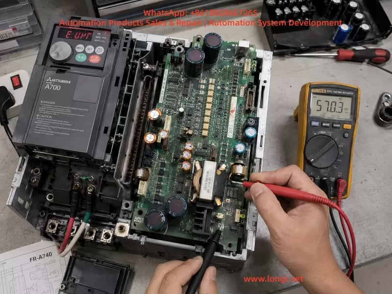
This document analyzes a real engineering case (380V input, 570V DC bus normal, persistent E.UVT alarm) and provides a systematic breakdown of the fault mechanism across three layers: power architecture, detection circuit, and control logic, along with a practical troubleshooting methodology.
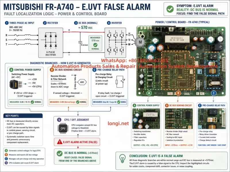
2. Power System Architecture and UVT Trigger Logic in FR-A740
2.1 Main Circuit Structure
The FR-A740 power path is structured as follows:
Three-phase 380–480VAC input
        ↓
Rectifier bridge (6-pulse conversion)
        ↓
DC bus capacitor bank (DC LINK ~510–580V)
        ↓
Pre-charge resistor + bypass relay
        ↓
IGBT inverter module
Under normal conditions:
| Parameter | Normal Range |
|---|---|
| AC Input | 380–480V |
| DC Bus | 510–580V |
| UVT Threshold | ~380–400V |
2.2 UVT Is Not a Direct Voltage Measurement
The E.UVT fault is not triggered by a single ADC measurement of DC voltage. Instead, it is determined by a combination of multiple system signals:
- DC bus divided voltage sensing signal
- Control power supply stability (SMPS output)
- CPU power-on initialization status (Power Good signal)
Therefore:
UVT ≠ Simple undervoltage detection
UVT = Power system instability or incomplete initialization
3. Engineering Contradiction in This Case
Observed parameters:
- Input: 380V normal
- DC bus: 570V normal
- Fault: Persistent E.UVT alarm
- Power board: Already inspected with visible aging signs
Key contradiction
If UVT were truly valid, the DC bus voltage should be below ~400V.
However, the measured value is 570V.
Therefore:
The fault is not in the power circuit, but in the detection or control circuit layer.
4. Four Primary Failure Mechanism Models of E.UVT Misalarm
4.1 Control Power Supply Transient Drop Model (Highest Probability)
Structure
The internal SMPS provides:
- +5V CPU logic supply
- +15V gate drive supply
- -15V analog supply (in some versions)
Failure mechanism
When the following occurs:
- Electrolytic capacitor degradation
- Startup instability of SMPS
- Instantaneous load surge
The system experiences:
At power-up:
DC BUS = normal
BUT
5V supply drops momentarily (milliseconds)
CPU logic response:
“Control power not ready → system abnormal → UVT triggered”
Typical characteristics
- Fault appears immediately at power-on
- DC voltage remains stable
- Restart does not resolve issue
- Common in aged units
4.2 DC Bus Voltage Sensing Drift Model
Structure
DC sensing path:
DC BUS → High-voltage resistor divider → Isolation optocoupler → ADC input
Failure mechanism
Common issues include:
- Resistor drift under high voltage stress
- Micro-cracks in solder joints
- Optocoupler degradation (CTR drop)
Result:
Actual DC = 570V
Detected value = falsely low
CPU misinterprets:
“DC bus undervoltage → UVT trigger”
Typical characteristics
- Intermittent fault
- Temperature-sensitive behavior
- DC voltage appears normal externally
4.3 Pre-charge Circuit Abnormality Model
Structure
AC input → Pre-charge resistor → DC bus capacitors
                         ↓
                Bypass relay short-circuit
Failure mechanism
If the relay:
- Fails to close
- Has oxidized contacts
- Has unstable drive signal
Then:
- DC bus may still measure normally
- But system logic detects “incomplete power establishment”
Result:
UVT triggered due to incomplete DC stabilization
4.4 Control Board Logic / EEPROM Abnormality Model
Structure
Core components:
- MCU control CPU
- EEPROM parameter storage
- Power-on initialization logic
Failure mechanism
- Corrupted EEPROM data
- Faulty initialization sequence
- Electrical noise interference
Result:
System interprets:
Power status = invalid
→ UVT triggered
5. Power Board Structure Analysis (Based on Field Images)
The inspected board contains three critical functional zones:
5.1 Switching Power Supply Section
Features:
- High-frequency transformer
- Multiple electrolytic capacitors
- PWM control IC
Function:
- Generates +5V / +15V / control voltages
👉 Most critical failure region
5.2 DC Voltage Sensing Circuit
Features:
- High-value resistor networks
- Optocoupler isolation
- Analog feedback paths
Function:
- DC bus voltage monitoring
👉 Primary source of false UVT detection
5.3 Relay and Drive Section
Features:
- Power relay
- Driver transistors / ICs
- RC snubber circuits
Function:
- Pre-charge bypass control
6. System-Level Fault Localization Method
Step 1: Verify Actual DC Stability
Use:
- Multimeter with MIN/MAX function or oscilloscope
Goal:
Detect transient voltage drops
Step 2: Check Control Power Supplies
Measure:
- +5V
- +15V
Decision:
| Condition | Conclusion |
|---|---|
| Stable | Power board likely OK |
| Drops | Power board failure |
Step 3: Observe Relay Operation
Check:
- Audible relay click
- Delay or abnormal switching behavior
Step 4: Validate DC Sensing Signal
Measure:
- Divider node voltage
- Compare with theoretical ratio
Step 5: Replacement Verification
Fastest industrial method:
- Swap power board
- Or swap control board
7. Most Probable Root Cause in This Case
Based on combined evidence:
Probability ranking
| Failure Mode | Probability |
|---|---|
| SMPS transient instability | ★★★★★ |
| DC sensing network drift | ★★★★ |
| Pre-charge relay issue | ★★★ |
| Control board logic fault | ★★ |
8. Engineering Maintenance Strategy Summary
For FR-A740 E.UVT false alarms:
Core principle
It is not a voltage shortage problem, but a power system initialization problem.
Repair priority
- Replace electrolytic capacitors in power supply section
- Inspect resistor divider network
- Check relay contacts and operation
- Verify control power stability during startup
9. Engineering Conclusion
The E.UVT false alarm in FR-A740 systems is fundamentally a “power system integrity and timing failure” rather than a true undervoltage condition. Correct diagnosis requires shifting from static DC voltage measurement to dynamic power-up behavior analysis.
10. Final Note
In industrial inverter maintenance practice:
UVT alarm does NOT necessarily indicate undervoltage
It often indicates power sequencing instability or signal misinterpretation