Posted on

Understanding and Troubleshooting Er.138 Faults on Inovance CS700 Crane Inverters

1. Introduction: Do Not Treat Er.138 as a Simple “Fault Code 138”

When an Inovance CS700 crane-duty inverter displays “Er.138,” many maintenance technicians immediately search for “fault code 138” in the user manual. In many cases, they cannot find a direct explanation, which leads to assumptions that the alarm is caused by hidden firmware functions, application-card issues, software version incompatibility, or internal inverter damage.

However, the display logic of the CS700 series should not be interpreted as a simple three-digit numerical fault code. The fault indication normally contains two parts:

  • Er: Fault indication prefix
  • 1: Fault severity level
  • 38: Specific fault number

Therefore, Er.138 should first be understood as Level-1 Fault No. 38, rather than a single independent “Fault 138.”

This distinction is important. If Er.138 is mistakenly interpreted as an extended application fault code, troubleshooting may be directed toward communication cards, crane process cards, or firmware. In reality, Level-1 faults generally involve drive performance, output capability, motor control stability, brake coordination, or safety-related operating conditions.

For crane applications, this requires serious attention. A crane drive is not comparable to a fan, pump, or conveyor inverter. The lifting mechanism involves suspended loads, mechanical brakes, reduction gearboxes, ropes or chains, load inertia, acceleration torque, deceleration energy, encoder feedback, and anti-drop safety logic. A fault in any of these areas can result in abnormal current, poor speed tracking, torque instability, brake drag, or protection trips.

Therefore, Er.138 should never be handled by simply pressing RESET repeatedly. It should be investigated as a system-level lifting-drive fault.
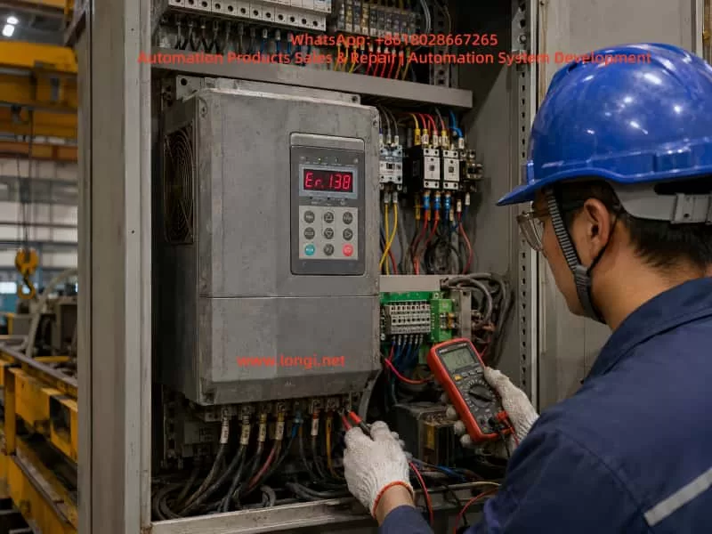

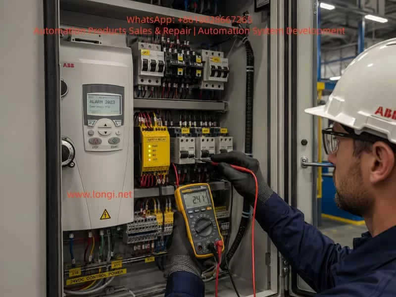
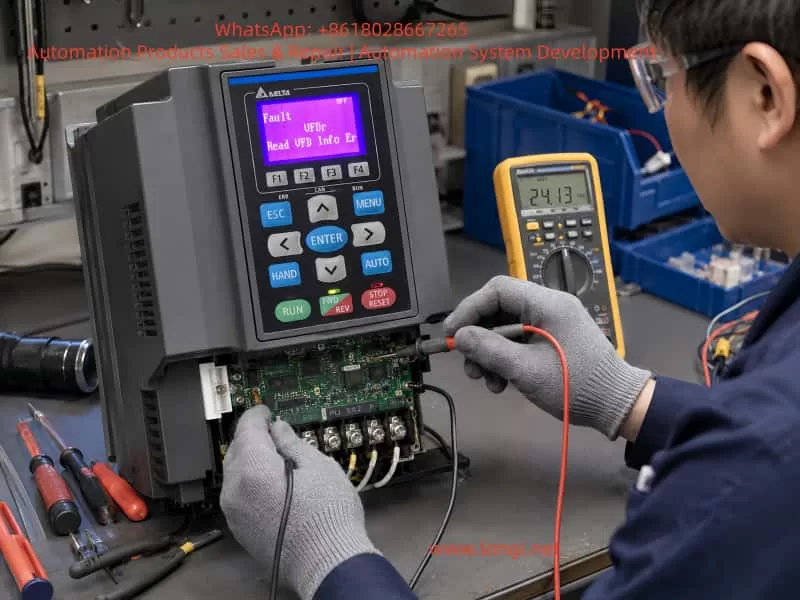
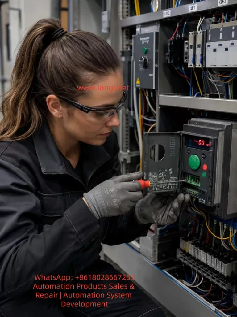
Industrial technician troubleshooting an Inovance CS700 crane-duty inverter displaying Er.138 inside a factory control cabinet, using a digital multimeter to inspect wiring and terminals.

2. Fault Severity Levels in CS700 Crane Drives

The CS700 crane inverter uses different fault levels to determine how the drive reacts after an abnormal condition is detected.

A Level-1 fault is generally displayed in the format Er.1xx. When such a fault occurs, the inverter stops output, brake-control logic may become invalid, the fault output becomes active, and the machine enters a free-stop or protective stop condition.

For a lifting mechanism, this is critical because the motor, brake, gearbox, and load must work together to prevent uncontrolled motion or load drop.

Other fault levels may use different stopping methods:

Fault LevelTypical Action
Level 1Output shutdown or free-stop protection
Level 2Fast stop
Level 3Deceleration stop
Level 4Warning or limited operation
Level 5Status indication or non-critical prompt

The “1” in Er.138 indicates that this is a Level-1 protective event. It should not be treated as a minor warning.

Before resetting or restarting the equipment, the following safety principles should be followed:

  • Ensure that no suspended load is in an unsafe position.
  • Lower the load to a safe position whenever possible.
  • Do not force the brake open.
  • Do not bypass safety interlocks.
  • Do not reduce protection thresholds merely to keep the equipment running.
  • Record the operating condition when the fault occurred.

A successful reset does not prove that the root cause has been removed.


3. General Troubleshooting Strategy for Er.138

A correct diagnosis begins by identifying when the fault occurs.

The same code can be triggered by very different causes depending on whether it appears:

  1. Immediately after power-on
  2. At the moment of start command
  3. During lifting
  4. During lowering
  5. During deceleration
  6. During direction reversal
  7. Only under heavy load
  8. Only after the machine has warmed up

This operating context is often more valuable than the code itself.

For example:

  • A fault immediately after power-on may indicate control-board, current-detection, encoder-interface, or parameter-related issues.
  • A fault during start-up may indicate brake drag, incorrect motor parameters, output wiring problems, motor connection errors, or mechanical seizure.
  • A fault during lifting may indicate overload, insufficient torque, low input voltage, gearbox resistance, or brake release problems.
  • A fault during lowering or deceleration may indicate braking resistor, regenerative energy, brake timing, or mechanical-inertia issues.
  • A fault during direction reversal may indicate incorrect brake timing, excessive acceleration/deceleration settings, encoder direction errors, or speed-tracking instability.

The diagnostic method should always follow the actual operating sequence instead of relying on trial-and-error parameter changes.
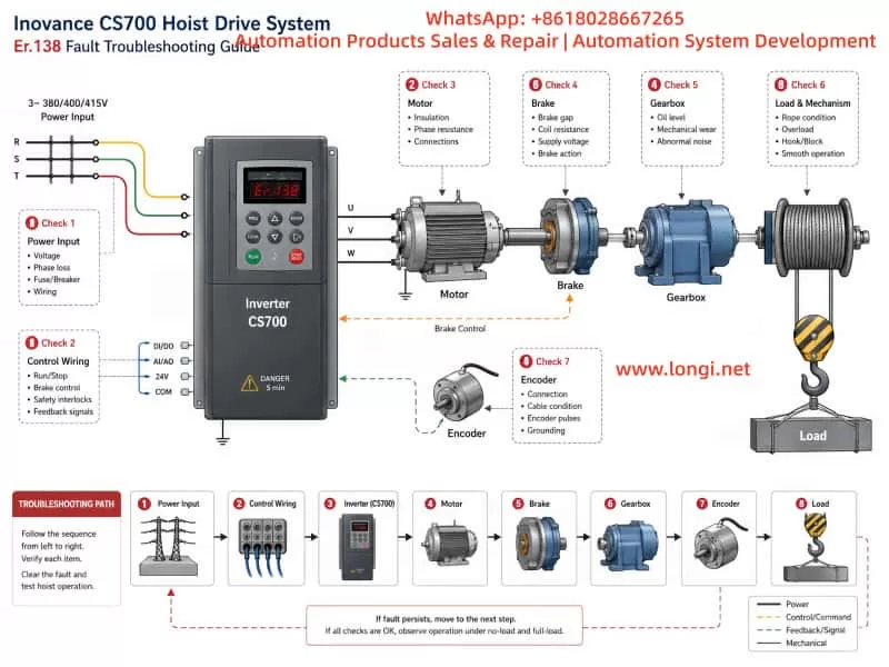

Technical troubleshooting diagram for an Inovance CS700 hoist drive system showing the inverter, motor, brake, gearbox, encoder, lifting drum, load, power input, and Er.138 fault inspection path.

4. Inspect the Input Power and Main Circuit First

Crane control panels are often installed in dusty, humid, vibrating, or high-temperature environments. Loose terminals, oxidized contactors, worn cables, damaged cable glands, and poor grounding are common in such equipment.

Many faults that appear to be inverter failures are actually caused by unstable input power or defective external wiring.

4.1 Check Three-Phase Input Voltage

Measure the voltage at the inverter input terminals and confirm:

  • The three-phase voltage is within the permitted range.
  • The voltage imbalance is minimal.
  • Voltage does not drop sharply during lifting.
  • Main contactor contacts are not burned or unstable.
  • Incoming terminals are securely tightened.
  • Circuit breakers and fuses are in good condition.
  • Input cables are correctly sized.
  • Large loads such as welding machines, presses, furnaces, or compressors are not causing major voltage fluctuations.

A crane may operate normally at no load but trip during lifting because voltage drops significantly when current demand rises.

If the supply voltage becomes unstable, the inverter may be unable to maintain sufficient motor torque. This can lead to abnormal drive performance, poor speed response, current fluctuations, or protective faults.

4.2 Inspect Motor Cables and Output Terminals

After disconnecting power and waiting for the DC bus capacitors to discharge, inspect:

  • U, V, and W motor cable insulation.
  • Motor terminal-box connections.
  • Cable damage caused by vibration, movement, crushing, or friction.
  • Loose lugs and oxidized terminals.
  • Water ingress in cable joints.
  • Output contactors or overload relays.
  • Motor winding resistance balance.
  • Insulation resistance between motor windings and ground.

A loose terminal may appear normal during static inspection but fail under vibration or high current. This is especially common in hoist systems where cables move repeatedly during operation.

4.3 Avoid Switching the Motor with an Output Contactor During Inverter Operation

The inverter should not be started and stopped by repeatedly switching an output contactor.

Opening or closing a contactor between the inverter and motor while the inverter is producing output can cause:

  • Sudden current interruption
  • Output voltage spikes
  • IGBT stress
  • Current detection errors
  • Motor torque loss
  • Protective tripping
  • Damage to the inverter power stage

The normal start-stop command should be sent through the inverter control terminals, keypad, PLC, or communication interface. Output contactors should be used only for isolation, maintenance, or carefully designed safety interlocking functions.


5. Mechanical Brake Problems Are a Major Cause of Crane Drive Faults

For lifting systems, the electromagnetic brake is not merely an accessory. It is one of the most important safety components in the entire drive system.

The inverter must establish motor torque before the mechanical brake releases. During stopping, the inverter must control motor deceleration before the brake closes. If these actions are not properly coordinated, the system can experience overload, speed loss, brake drag, current peaks, or unstable motion.

5.1 What Happens When the Brake Does Not Fully Release?

If the inverter begins producing torque but the brake remains partially applied, the motor must overcome:

  • Brake friction
  • Mechanical transmission resistance
  • Static friction in the gearbox
  • Load gravity
  • Rope or drum resistance
  • Misalignment in couplings or shafts

This produces high current and poor speed buildup.

Typical symptoms include:

  • Motor humming without movement.
  • High current at low frequency.
  • Lift movement much slower than commanded.
  • Normal lowering but abnormal lifting.
  • Heavy-load lifting faults.
  • Brake coil energizes but brake does not fully open.
  • Abnormal rubbing noise near the brake.
  • Equipment works when cold but faults after heating.

5.2 Check the Brake Electrical Circuit

The following items should be inspected:

  • Brake coil rated voltage.
  • Actual brake coil voltage during operation.
  • Brake rectifier output voltage.
  • Brake contactor condition.
  • Intermediate relay condition.
  • Coil resistance.
  • Coil overheating.
  • Burned smell or discoloration.
  • Loose control wiring.
  • Faulty auxiliary contacts.
  • Timing between inverter torque output and brake release signal.

A damaged brake rectifier may produce insufficient DC voltage, causing the brake to release weakly. The brake may make a clicking sound but still fail to open fully.

5.3 Check the Brake Mechanical Assembly

Even if the electrical signal is correct, the brake mechanism may still be defective. Inspect:

  • Brake shoe wear.
  • Brake wheel wear or corrosion.
  • Brake gap setting.
  • Spring preload.
  • Brake lever movement.
  • Electromagnet plunger movement.
  • Pivot pins and shafts.
  • Brake wheel oil contamination.
  • Mechanical sticking.
  • Uneven brake-shoe contact.
  • Brake drag after release.

In dusty, humid, or outdoor crane environments, brake mechanisms often become corroded or contaminated. Parameter adjustment cannot solve a mechanically sticking brake.


6. Incorrect Motor Parameters Can Cause Vector-Control Instability

The CS700 crane inverter can operate in vector-control modes. Vector control provides strong low-speed torque and good speed regulation, making it suitable for hoisting applications.

However, vector control relies heavily on correct motor parameters.

If motor power, voltage, current, speed, frequency, pole number, or control mode is incorrect, the inverter cannot calculate the motor magnetic model accurately. This may result in poor torque output, unstable speed control, excessive current, or protection trips.

6.1 Verify All Motor Nameplate Data

The following parameters should be checked against the motor nameplate:

  • Rated power
  • Rated voltage
  • Rated current
  • Rated frequency
  • Rated speed
  • Number of poles
  • Connection method
  • Rated power factor
  • Motor efficiency
  • Cooling method
  • Encoder type, if installed

A common site problem occurs after motor replacement. The old motor parameters remain in the inverter, while the new motor has different current, speed, or pole number.

Another common error is incorrect star-delta connection. For example, a motor designed for 380 V delta connection may be connected in star, resulting in reduced torque and poor lifting performance.

6.2 Motor Auto-Tuning Must Be Performed Safely

Motor tuning should not be treated as a simple push-button operation.

Before tuning, confirm:

  • The load is in a safe position.
  • The brake logic is safe.
  • The motor can rotate safely if dynamic tuning is selected.
  • Motor wiring is correct.
  • Motor insulation is acceptable.
  • Nameplate parameters are already entered.
  • The selected tuning method is suitable for the mechanical condition.

If the motor is mechanically connected to a suspended load, static tuning may be safer than rotating tuning. Dynamic tuning under unsafe conditions can create unexpected movement and serious risk.

6.3 Do Not Blindly Increase Torque Boost

When lifting torque is insufficient, some technicians immediately increase torque boost.

A moderate torque-boost adjustment can help low-speed starting, but it is not a solution for brake drag, incorrect motor parameters, mechanical seizure, voltage drop, or overload.

Excessive torque boost can cause:

  • Motor overheating
  • Excessive current
  • Increased inverter stress
  • Reduced efficiency
  • Poor control stability

The correct sequence is:

  1. Verify motor parameters.
  2. Verify brake release.
  3. Inspect mechanical resistance.
  4. Check power supply stability.
  5. Confirm motor condition.
  6. Adjust torque-related parameters only after the above checks.

7. Encoder and Speed Feedback Problems Must Be Considered

Many crane systems use encoder feedback for closed-loop vector control, precise positioning, speed regulation, anti-sway functions, or anti-drop control.

If the encoder signal is unstable, reversed, noisy, or intermittent, the inverter may calculate incorrect motor speed and torque.

7.1 Typical Encoder Fault Symptoms

Encoder problems may appear as:

  • Normal operation when cold but faults after heating.
  • Normal low-speed operation but faults at high speed.
  • Random speed fluctuation.
  • Unstable hoist stopping position.
  • Motor current oscillation.
  • Faults only in one direction.
  • Abnormal creeping at zero speed.
  • Sudden speed feedback jumps.
  • Faults that occur after vibration or cable movement.

7.2 Encoder Inspection Checklist

Check the following:

  • Encoder supply voltage stability.
  • A/B/Z signal integrity.
  • Differential signal quality.
  • Encoder cable shield grounding.
  • Cable routing away from motor power cables.
  • Encoder coupling tightness.
  • Encoder shaft movement.
  • Connector condition.
  • Encoder resolution settings.
  • Encoder direction settings.
  • PG card condition.
  • Grounding and noise interference.

Encoder cables should use shielded twisted-pair cable whenever possible. They should be routed separately from motor cables. If crossing is necessary, cross at approximately 90 degrees rather than running parallel over a long distance.


8. Mechanical Resistance Must Not Be Underestimated

The lifting mechanism includes the motor, coupling, gearbox, drum, bearings, wire rope, pulley blocks, hooks, brakes, and limit devices.

Any abnormal resistance in these components increases motor torque demand.

8.1 Common Mechanical Causes

Typical mechanical causes include:

  • Gearbox lubrication failure
  • Damaged gears
  • Bearing seizure
  • Coupling misalignment
  • Drum deformation
  • Rope overlap or rope jamming
  • Pulley seizure
  • Brake drag
  • Motor bearing damage
  • Shaft misalignment
  • Limit switch interference
  • Gearbox output shaft binding
  • Structural deformation of the lifting mechanism

8.2 Use Motor Current as a Diagnostic Indicator

Motor current provides valuable information.

Under comparable conditions, observe:

  • Whether the three output currents are balanced.
  • Whether lifting current is much higher than lowering current.
  • Whether no-load current is already high.
  • Whether current spikes occur at brake release.
  • Whether current rises sharply at a certain mechanical position.
  • Whether current fluctuates with vibration.

If no-load current is abnormally high, suspect brake drag, mechanical resistance, bearing failure, or gearbox problems.

If lifting current is much higher than lowering current, inspect load condition, brake release, mechanical resistance, and gearbox efficiency.

If phase currents are clearly unbalanced, inspect motor windings, output cables, terminals, and contactors.


9. Acceleration and Deceleration Settings Must Match the Hoisting System

A crane cannot be configured using aggressive acceleration and deceleration values without considering load inertia, brake timing, motor torque capability, and regenerative energy.

9.1 Risks of Excessively Short Acceleration Time

If acceleration time is too short, the inverter must rapidly establish torque while overcoming brake release delay, static friction, suspended-load gravity, rope tension changes, and gearbox inertia.

This can result in:

  • Excessive current
  • Poor speed tracking
  • Torque saturation
  • Brake drag symptoms
  • Mechanical shock
  • Protective faults

A lifting mechanism should normally have a carefully designed low-speed starting stage and smooth acceleration profile.

9.2 Risks of Excessively Short Deceleration Time

During deceleration, a hoist may enter regenerative operation. Mechanical energy is returned to the inverter DC bus.

If the braking resistor, braking unit, or energy-dissipation capability is insufficient, the DC bus voltage may rise rapidly.

This can cause:

  • Overvoltage faults
  • Braking faults
  • Sudden deceleration instability
  • Mechanical shock
  • Brake timing problems
  • Load swing

Deceleration time should be set based on:

  • Load weight
  • Hoisting speed
  • Gear ratio
  • Drum diameter
  • Braking resistor power
  • Braking resistor resistance
  • Duty cycle
  • Frequency of lifting and lowering
  • Mechanical inertia
  • Required stopping distance

9.3 Avoid Sudden Multi-Speed Switching

If multi-speed control is used, large step changes should be avoided.

Use smooth acceleration and deceleration curves, including S-curves when appropriate. This reduces mechanical impact, current spikes, and load swing.


10. Check the Braking Resistor and Braking Unit

In crane applications, braking components are especially important during lowering, deceleration, and frequent reversing.

A braking resistor with incorrect resistance, insufficient power rating, poor wiring, overheating, or open circuit can cause abnormal drive behavior.

10.1 Inspect the Braking Resistor

Check:

  • Burn marks or discoloration.
  • Loose terminals.
  • Measured resistance value.
  • Correct power rating.
  • Proper ventilation.
  • Cooling fan operation, if installed.
  • Cable size and length.
  • Connection tightness.
  • Signs of overheating.
  • Installation away from flammable materials.

10.2 Do Not Reduce Resistance Arbitrarily

Some users install a lower-resistance braking resistor to obtain stronger braking.

This can be dangerous because lower resistance increases braking current. If the resistance is below the permitted range, the braking unit or inverter power stage may be overloaded and damaged.

The braking resistor value must match the inverter and braking-unit specifications.

10.3 Lowering Operation Often Reveals Braking Problems

When lowering a suspended load, gravity drives the motor. The motor can become a generator and return energy to the inverter DC bus.

Therefore, if faults occur mainly during lowering, rapid deceleration, emergency stop, or direction reversal, inspect:

  • Braking resistor
  • Braking unit
  • Deceleration time
  • Brake closing sequence
  • Mechanical inertia
  • DC bus voltage behavior

11. Recommended Field Troubleshooting Procedure

The following workflow can be used when a CS700 crane inverter displays Er.138.

Step 1: Confirm the Display Carefully

Verify that the display is truly Er.138 and not a similar-looking code caused by LED digit interpretation.

Take a clear photo and record:

  • Fault code
  • Load condition
  • Operating direction
  • Running speed
  • Whether the brake was open
  • Whether the fault occurred during start, run, stop, or reverse

Step 2: Record the Fault Condition

Document:

  • Lifting or lowering direction
  • No-load, light-load, or full-load condition
  • Cold machine or hot machine condition
  • Immediate or delayed trip
  • Frequency of occurrence
  • Recent maintenance history
  • Recent replacement of motor, brake, encoder, gearbox, or inverter
  • Whether reset is possible

Step 3: Inspect Main Power and Wiring

After isolating power and waiting for capacitor discharge:

  • Check incoming supply voltage.
  • Check U/V/W connections.
  • Check motor cable condition.
  • Check grounding.
  • Check motor insulation.
  • Check contactors and terminals.
  • Check for heat damage or loose connections.

Step 4: Verify Motor Parameters

Compare inverter settings with the motor nameplate. Back up existing inverter parameters before making changes. Enter correct motor data and perform a suitable motor tuning procedure.

Step 5: Inspect Brake Operation

Confirm brake release voltage, brake coil condition, rectifier output, contactor operation, brake gap, brake shoe condition, and actual mechanical opening movement.

Step 6: Inspect Mechanical Components

Check the gearbox, bearings, drum, rope, pulley, coupling, and brake wheel. If necessary, separate the motor from the mechanical load and test the motor alone.

Step 7: Check Encoder Feedback

For closed-loop systems, verify encoder voltage, wiring, shield grounding, signal integrity, coupling, direction, resolution, and PG interface condition.

Step 8: Inspect Braking Components and Motion Parameters

Check braking resistor value, resistor power, braking-unit condition, deceleration time, acceleration time, speed-change logic, and brake timing parameters.

Step 9: Perform Low-Risk Test Runs

After repairs or adjustments, begin with low-speed no-load testing. Increase speed and load gradually. Do not immediately perform full-load lifting before confirming that current, speed, brake action, and mechanical operation are stable.


12. Common Mistakes to Avoid

Mistake 1: Repeatedly Pressing RESET

Resetting only clears the current fault condition. It does not remove the underlying cause.

Mistake 2: Restoring Factory Settings Without Backup

A crane inverter contains critical parameters for motor data, brake timing, speed settings, limit logic, encoder configuration, and control terminals.

Restoring factory settings can create new hazards, including incorrect direction, unsafe brake timing, or loss of operational logic.

Mistake 3: Bypassing the Mechanical Brake

The brake is a safety device. Forcing it open or bypassing it may lead to uncontrolled load movement.

Mistake 4: Replacing the Inverter Without Checking the System

A new inverter may fail again if the true cause is brake drag, encoder failure, low input voltage, damaged motor cable, gearbox resistance, or incorrect motor settings.

Mistake 5: Solving Every Problem by Changing Parameters

Parameter changes should be based on measurements and system verification. Mechanical, electrical, and feedback faults cannot be reliably corrected through parameter adjustment alone.


13. Preventive Maintenance Recommendations

To reduce Er.138-type faults and other crane-drive failures, establish a preventive maintenance plan.

Monthly checks should include:

  • Cabinet cleaning
  • Cooling fan condition
  • Filter condition
  • Terminal tightening
  • Grounding inspection
  • Contactor condition
  • Brake movement observation

Quarterly checks should include:

  • Brake coil voltage
  • Brake rectifier condition
  • Brake shoe wear
  • Brake gap setting
  • Brake wheel condition
  • Motor cable inspection
  • Encoder connector inspection

Semi-annual checks should include:

  • Motor insulation resistance
  • Gearbox lubrication
  • Bearing condition
  • Braking resistor condition
  • Braking-unit connections
  • Parameter backup
  • Fault-history review

Annual checks should include:

  • Full inspection of brake timing
  • Motor parameter verification
  • Encoder feedback verification
  • Mechanical load test
  • Safety interlock verification
  • Wire rope and drum inspection
  • Gearbox efficiency evaluation

For high-duty crane systems, special attention should be given to brake wear, contactor life, braking resistor heat aging, fan life, encoder cable integrity, motor bearings, and gearbox lubrication.


14. Conclusion

When an Inovance CS700 crane inverter displays Er.138, it should not be treated as a simple “fault 138.” It should first be interpreted as a Level-1 drive fault, requiring careful evaluation of the entire hoisting system.

The investigation should include:

  • Input power quality
  • Output wiring
  • Motor condition
  • Motor parameters
  • Brake release and brake timing
  • Mechanical resistance
  • Encoder feedback
  • Braking resistor and braking unit
  • Acceleration and deceleration settings
  • Load condition and operating sequence

The objective is not merely to reset the inverter and resume operation. The real goal is to identify why the protection was triggered and verify that the lifting system can return to service safely.

For crane equipment, safe recovery is always more important than rapid recovery.
Posted on

Oxygen Analyzer “Slope Out of Range” Alarm During Calibration: Causes, Diagnostic Logic, and Field Troubleshooting Guide

Introduction

Online oxygen analyzers are widely used in pharmaceutical water systems, chemical processes, power plants, fermentation systems, inert gas protection, combustion control, metallurgical processes, environmental monitoring, and industrial gas production. In many of these applications, dissolved oxygen or gaseous oxygen concentration is a critical process variable. Incorrect oxygen measurement can lead to poor product quality, unsafe operating conditions, increased corrosion risk, excessive energy consumption, unstable combustion, or unreliable process control.

Electrochemical oxygen sensors remain common because they are relatively economical, sensitive, and suitable for continuous online measurement. However, these sensors require periodic calibration and maintenance. One of the most common calibration-related alarms is:

Slope Out of Range

On some Mettler Toledo M400 oxygen analyzer systems, the alarm may appear together with an abnormal slope value, such as:

O2 slope -2000 mV

This condition often occurs after an air calibration attempt. The analyzer may display an oxygen value close to zero, fail to complete calibration, or continue operating with an alarm active.

This article explains the technical meaning of the slope alarm, the electrochemical principle behind the measurement, the likely causes, the correct calibration conditions, and a practical field troubleshooting procedure.


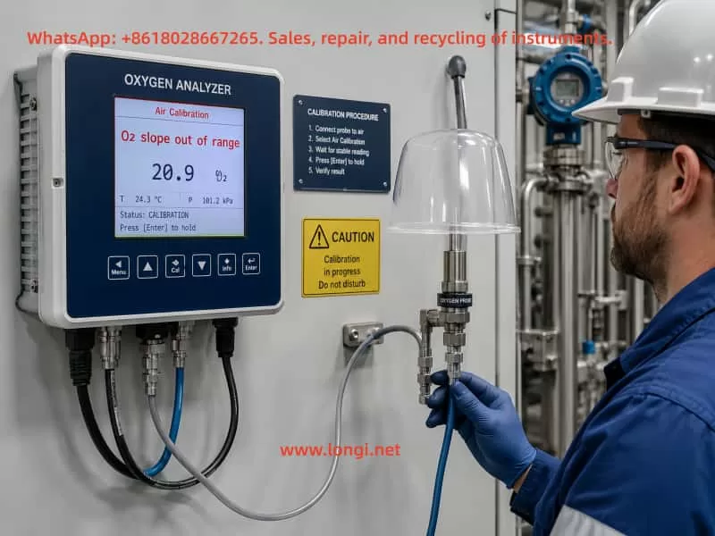
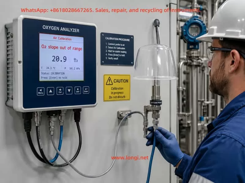
Industrial technician performing air calibration on an online oxygen analyzer showing an O2 slope out of range alarm.

1. What Does “Slope Out of Range” Mean?

The slope value represents the sensitivity of the oxygen sensor.

During calibration, the analyzer compares the sensor signal at a known oxygen condition with the expected oxygen value. For example, during air calibration, the sensor is exposed to atmospheric air containing approximately 20.9% oxygen. The analyzer measures the sensor response and calculates whether the sensor sensitivity is still within the acceptable range.

If the calculated sensor sensitivity is too high, too low, unstable, negative, or otherwise outside the configured acceptable limits, the analyzer generates a:

Slope Out of Range Alarm

In practical terms, this means:

The analyzer cannot establish a valid relationship between the actual oxygen concentration and the electrical signal generated by the sensor.

The alarm is therefore not simply a display issue. It indicates that either the sensor, calibration condition, signal connection, or stored calibration data is abnormal.


2. The Technical Meaning of Sensor Slope

An oxygen analyzer does not directly detect ppm or percentage oxygen values. The sensor produces an electrical signal, usually a small current or voltage. The analyzer converts that electrical signal into an oxygen concentration using calibration parameters.

A simplified measurement relationship can be written as:

[
O_2 = k \times S + b
]

Where:

  • (O_2) = oxygen concentration
  • (S) = sensor electrical signal
  • (k) = slope or sensitivity factor
  • (b) = offset or zero-point compensation

The slope parameter determines how much the measured oxygen value changes when the sensor signal changes.

A healthy sensor should produce a stable and repeatable response under standard calibration conditions. If the sensor is aged, contaminated, damaged, dry, electrically unstable, or incorrectly calibrated, the slope value may become invalid.

An extreme slope value such as -2000 mV generally indicates that the analyzer has detected an abnormal sensor response or has failed to calculate a valid calibration factor.


3. Basic Operating Principle of Electrochemical Oxygen Sensors

Many industrial oxygen analyzers use electrochemical sensor technology. Depending on the design, the sensor may be a Clark-type polarographic sensor, galvanic oxygen sensor, or similar electrochemical system.

A typical electrochemical oxygen sensor contains:

  • Cathode
  • Anode
  • Electrolyte
  • Oxygen-permeable membrane
  • Electrical connection system
  • Temperature measurement element in some models

Oxygen molecules diffuse through the membrane and enter the electrolyte. A controlled electrochemical reaction occurs at the electrode surface. This reaction generates a signal proportional to the oxygen partial pressure or dissolved oxygen concentration.

A simplified oxygen reduction reaction is:

[
O_2 + 4e^- + 2H_2O \rightarrow 4OH^-
]

The generated current is measured by the analyzer. The analyzer then applies the calibration slope and offset values to calculate the oxygen concentration.

Because the membrane, electrolyte, electrodes, and internal chemistry all affect sensor response, the sensor is considered a consumable component. It cannot maintain perfect sensitivity indefinitely.


4. Why the Membrane Must Remain Installed During Calibration

A common misunderstanding is that the membrane should be removed during calibration. This is incorrect.

For electrochemical oxygen sensors, the membrane is part of the sensing system. It controls oxygen diffusion into the electrolyte and directly affects the sensor response. Removing the membrane changes the diffusion characteristics and exposes the internal electrode system to the environment.

Therefore:

  • The membrane must remain installed during normal calibration.
  • The membrane must be intact and properly fitted.
  • The membrane must not be torn, loose, dry, wrinkled, contaminated, or leaking.
  • The electrolyte condition must be suitable for normal sensor operation.

Calibration should always be performed with the complete sensor assembly in its normal measuring condition.

Removing the membrane during calibration can cause unstable readings, unrealistic sensitivity values, electrolyte contamination, and invalid calibration results.


Oxygen probe maintenance and slope alarm diagnosis, showing membrane inspection, electrolyte service, connector checks, and recalibration tools.

5. Main Causes of Slope Out of Range Alarms

The causes can generally be divided into four groups:

  1. Sensor-related faults
  2. Calibration condition problems
  3. Electrical connection or signal-chain problems
  4. Analyzer configuration or stored-data problems

Each group should be checked systematically.


6. Sensor-Related Causes

6.1 Sensor Aging

Sensor aging is the most common reason for slope alarms.

Over time, the electrochemical reaction becomes less efficient. The electrode surface may deteriorate, the electrolyte may lose performance, and the membrane permeability may change. The sensor output gradually becomes weaker or less stable.

Typical signs of sensor aging include:

  • Slow response time
  • Calibration takes much longer than normal
  • Repeated calibration failures
  • Slope value gradually decreasing over time
  • Unstable readings in air
  • Oxygen value remains near zero or fluctuates abnormally
  • The analyzer cannot accept a new calibration

When a sensor reaches the end of its useful life, calibration cannot restore normal performance. The sensor must be serviced or replaced.


6.2 Electrolyte Depletion or Contamination

The electrolyte is essential for the internal electrochemical reaction.

Possible electrolyte-related problems include:

  • Electrolyte evaporation
  • Electrolyte leakage
  • Long-term storage without proper maintenance
  • Contamination by process media
  • Incorrect electrolyte type
  • Air bubbles trapped inside the sensor
  • Incorrect refill procedure

If the electrolyte has deteriorated, the electrical response of the sensor may become weak, noisy, delayed, or non-linear. This can result in an unacceptable slope value during calibration.

For sensors with replaceable electrolyte, the electrolyte should be replaced according to the manufacturer’s maintenance procedure. For sealed sensors, the complete sensor may need replacement.


6.3 Damaged or Contaminated Membrane

The membrane controls how oxygen enters the sensor. Even minor membrane damage can cause major calibration problems.

Common membrane issues include:

  • Puncture or tear
  • Scratches
  • Wrinkles
  • Improper tension
  • Chemical attack
  • Oil contamination
  • Protein or biological fouling
  • Mineral deposits
  • Dry or brittle membrane
  • Membrane cap not tightened correctly

A damaged membrane may allow oxygen to diffuse too quickly, too slowly, or inconsistently. This creates unstable sensor output and can produce a slope alarm.

A contaminated membrane can also reduce oxygen diffusion. The analyzer may then interpret the weak response as sensor degradation.


6.4 Electrode Contamination or Chemical Poisoning

Certain process environments can poison or contaminate the electrode system. Sulfur-containing gases, aggressive chemicals, oil vapor, solvents, chlorine compounds, or biological contamination may affect sensor performance.

Possible symptoms include:

  • Sudden slope reduction
  • Very slow response
  • Failure after exposure to a specific process gas
  • Temporary recovery after cleaning, followed by repeated failure
  • Calibration success in clean air but unstable measurement in process conditions

In such cases, the process medium, sensor installation location, sample conditioning system, and maintenance interval should all be reviewed.


6.5 Sensor Dry-Out During Storage or Shutdown

Some oxygen sensors require proper storage conditions. If a sensor is stored dry or left out of service for a long period, the electrolyte system may become unstable.

Possible results include:

  • Delayed sensor polarization
  • Low sensitivity
  • High baseline drift
  • Failed calibration
  • Slope out of range alarm

A sensor that has been stored incorrectly may require reconditioning, electrolyte replacement, membrane replacement, or complete replacement depending on the sensor design.


7. Calibration Condition Problems

Not every slope alarm means the sensor is defective. Incorrect calibration conditions can also produce an invalid slope value.

7.1 Unstable Air Flow

Air calibration requires stable exposure to atmospheric oxygen.

Common field mistakes include:

  • Blowing air directly onto the sensor by mouth
  • Using an unstable compressed-air source
  • Holding the sensor in moving air
  • Using an air calibration hood with leaks
  • Rapidly moving the sensor during calibration
  • Using a temporary enclosure with fluctuating humidity

A fast or irregular air stream can create unstable oxygen diffusion across the membrane. The sensor signal may fluctuate and the analyzer may reject the calibration.

The best approach is to use a proper calibration cap, calibration chamber, or stable reference gas arrangement recommended by the sensor manufacturer.


7.2 Insufficient Stabilization Time

The sensor must reach a stable signal before calibration is accepted.

If calibration is confirmed too early, the analyzer may calculate the slope from an unstable signal. This can produce false calibration failure or an abnormal slope.

The stabilization time depends on:

  • Sensor type
  • Previous oxygen level
  • Temperature
  • Membrane condition
  • Process pressure
  • Sensor age
  • Electrolyte condition
  • Air flow condition

A sensor recently removed from a low-oxygen process may need several minutes or longer to stabilize in air.


7.3 Incorrect Temperature Conditions

Oxygen sensor response is temperature-dependent. Most analyzers include temperature compensation, but calibration should still be performed under stable temperature conditions.

Problems may occur when:

  • The sensor temperature is changing rapidly
  • The sensor is removed from a hot process and immediately calibrated in cool air
  • The temperature element is faulty
  • The sensor is exposed to direct sunlight or heater radiation
  • The calibration gas temperature differs significantly from the process condition

A stable ambient temperature is preferred. For general field calibration, a stable environment around 20–25°C is often suitable, but the correct procedure should follow the sensor manufacturer’s requirements.


7.4 Incorrect Pressure Compensation

Oxygen partial pressure depends on atmospheric pressure. For gas-phase oxygen measurement, pressure compensation may significantly influence calibration accuracy.

Potential issues include:

  • Incorrect barometric pressure setting
  • Calibration performed under vacuum or elevated pressure
  • Instrument pressure compensation disabled
  • Incorrect process pressure input
  • Blocked pressure sensor line in sample systems

If pressure data are wrong, the analyzer may calculate an incorrect expected oxygen value and reject the calibration.


7.5 Moisture and Humidity Effects

Air contains water vapor, and humidity can affect oxygen partial pressure. In some applications, calibration gas moisture must be controlled.

Potential problems include:

  • Condensation on the membrane
  • High humidity causing slow stabilization
  • Water droplets on the sensor
  • Wet calibration cap
  • Dry gas calibration used for a wet process without compensation

The membrane surface should be clean and free from liquid water droplets unless the calibration procedure specifically requires wet conditions.


8. Electrical Connection and Signal-Chain Problems

If the sensor itself appears physically normal, the next step is to inspect the electrical signal path.

8.1 Loose or Oxidized Connector

Sensor connectors may become oxidized, loose, contaminated, or damaged due to humidity, vibration, chemicals, or repeated plugging and unplugging.

Possible symptoms include:

  • Intermittent readings
  • Sudden jumps in oxygen value
  • Calibration starts but fails randomly
  • Slope value changes dramatically between attempts
  • Analyzer reports sensor communication or diagnostic warnings

The connector should be inspected for:

  • Corrosion
  • Moisture
  • Bent pins
  • Loose locking ring
  • Damaged sealing gasket
  • Oil or chemical contamination

Always power down or follow the manufacturer’s connection procedure before disconnecting the sensor.


8.2 Damaged Cable or Shielding

A damaged sensor cable may introduce noise or cause intermittent open-circuit conditions.

Potential cable problems include:

  • Broken conductor
  • Crushed cable
  • Rodent damage
  • Water ingress
  • Damaged shield
  • Improper grounding
  • Cable routed beside high-power inverter output cables
  • Poor terminal connection

In industrial environments, oxygen sensor signals are often very small. Electromagnetic interference from variable frequency drives, contactors, heaters, welding equipment, or unshielded power cables may disturb the measurement.

The sensor cable should be routed away from high-voltage and high-current wiring. Shielding and grounding should follow the manufacturer’s wiring recommendations.


8.3 Analyzer Input Circuit Problems

Although less common than sensor failure, the analyzer input stage can also be defective.

Possible causes include:

  • Internal analog input failure
  • Moisture ingress
  • Power supply instability
  • Damaged sensor interface board
  • Incorrect channel configuration
  • Firmware or hardware fault

A useful troubleshooting method is to connect a known-good sensor to the analyzer. If the known-good sensor calibrates normally, the original sensor is likely defective. If the known-good sensor also fails, the analyzer or wiring system should be investigated.


9. Analyzer Configuration and Calibration Data Problems

9.1 Incorrect Sensor Type Selection

The analyzer must be configured for the correct sensor type and measurement range.

Possible configuration errors include:

  • Wrong sensor technology selected
  • Incorrect oxygen range
  • Wrong calibration mode
  • Wrong units
  • Incorrect membrane or sensor parameter settings
  • Incorrect temperature compensation setting
  • Wrong process pressure configuration

If the analyzer configuration does not match the installed sensor, the slope calculation may be invalid.


9.2 Stored Calibration Data Corruption

In some cases, previous failed calibrations or incorrect parameter changes may leave invalid calibration data in memory.

Symptoms may include:

  • Alarm remains active after a seemingly successful calibration
  • Analyzer displays unrealistic slope values
  • Calibration acceptance behavior is inconsistent
  • Sensor value remains fixed after calibration

The corrective action may include:

  • Resetting calibration data
  • Restoring sensor calibration defaults
  • Clearing invalid calibration history
  • Reconfiguring the sensor channel
  • Performing a complete zero and span calibration

The exact menu path depends on the analyzer version and sensor configuration.


9.3 Slope Acceptance Limits Set Too Narrow

Some systems allow the acceptable slope range to be configured. If the limits are set too narrow, a sensor that is still usable may be rejected.

However, slope limits should not be widened simply to remove the alarm. Doing so may hide a genuine sensor degradation issue and create inaccurate oxygen measurement.

Any change to acceptance limits should be based on:

  • Manufacturer specifications
  • Process quality requirements
  • Sensor history
  • Validation procedures
  • Maintenance documentation

10. Practical Field Troubleshooting Procedure

The following sequence is suitable for a typical electrochemical oxygen analyzer showing a slope out of range alarm after air calibration.

Step 1: Confirm the Alarm Information

Record the following information before making changes:

  • Analyzer model
  • Sensor model
  • Current oxygen reading
  • Temperature reading
  • Slope value
  • Calibration date
  • Previous successful calibration date
  • Process conditions
  • Sensor installation location
  • Sensor age
  • Membrane or electrolyte replacement history

A slope value such as -2000 mV should be treated as a significant abnormal condition, not as a minor calibration drift.


Step 2: Inspect the Sensor Physically

Check the sensor for:

  • Membrane damage
  • Membrane contamination
  • Loose membrane cap
  • Electrolyte leakage
  • Dry sensor condition
  • Cracks in the sensor body
  • Moisture in electrical connector
  • Corrosion at connector pins
  • Damage caused by process chemicals

If the membrane is damaged or the electrolyte is contaminated, the sensor should be serviced before attempting another calibration.


Step 3: Confirm That the Membrane Is Installed

The membrane must remain installed during calibration.

Do not remove the membrane for air calibration.

The sensor should be calibrated in its normal operating configuration. If the membrane has been removed, replaced, or disturbed, the sensor may require reconditioning time before calibration.


Step 4: Allow the Sensor to Stabilize

Place the sensor in a stable calibration environment.

For air calibration:

  • Use clean ambient air or approved calibration gas.
  • Avoid blowing directly on the sensor.
  • Avoid unstable compressed-air flow.
  • Keep the sensor temperature stable.
  • Allow enough time for the reading to stabilize.
  • Do not confirm calibration until the analyzer indicates stability.

If the analyzer provides a stability indicator, wait until it meets the acceptance condition.


Step 5: Perform Calibration Again

Perform the correct calibration sequence according to the sensor type:

  • Air calibration only, if applicable
  • Zero calibration followed by air/span calibration
  • Calibration with certified gas, if required by the process
  • Calibration under controlled pressure and humidity conditions, if applicable

Do not repeatedly force calibration acceptance if the analyzer rejects the result. Repeated failed calibrations may overwrite useful diagnostic information.


Step 6: Check Electrical Connections

Inspect and test:

  • Sensor plug
  • Cable condition
  • Connector locking
  • Shielding
  • Grounding
  • Junction boxes
  • Terminal blocks
  • Cable routing near inverter or motor cables

Re-seat the connector and ensure it is fully locked. If possible, test the sensor with another compatible cable or analyzer input channel.


Step 7: Reset Invalid Calibration Data

If the sensor, membrane, electrolyte, calibration environment, and wiring all appear normal, reset the stored calibration data according to the analyzer service procedure.

Possible actions may include:

  • Clear calibration data
  • Restore calibration defaults
  • Reset sensor calibration
  • Delete failed calibration history
  • Reconfigure the measurement channel

After the reset, repeat the complete calibration procedure under stable conditions.


Step 8: Test with a Known-Good Sensor

This is one of the most effective fault-isolation methods.

Connect a known-good compatible sensor to the same analyzer and cable.

Results can be interpreted as follows:

Test ResultLikely Cause
Known-good sensor calibrates normallyOriginal sensor is defective or requires service
Known-good sensor also failsAnalyzer, cable, wiring, configuration, or calibration conditions are likely abnormal
Both sensors show unstable readingsPossible electrical noise, grounding, cable damage, or environmental instability
Original sensor works on another analyzerOriginal analyzer channel may be defective

11. Can the Alarm Be Cleared Manually?

In most systems, a slope alarm should not be treated as a simple message that can be manually erased.

The alarm is normally cleared only after the analyzer recognizes a valid sensor condition. This usually requires one of the following:

  • Successful calibration
  • Corrected sensor condition
  • Repaired cable or connector
  • Replacement of membrane or electrolyte
  • Replacement of the sensor
  • Reset and successful recalibration
  • Correct analyzer configuration

Simply acknowledging or muting the alarm may silence the message temporarily, but it will not restore measurement accuracy.

The correct objective is not only to clear the alarm. The objective is to restore a valid and traceable oxygen measurement.


12. When Should the Sensor Be Replaced?

Sensor replacement should be considered when one or more of the following conditions are present:

  • Calibration repeatedly fails under controlled conditions
  • Slope remains outside the acceptable range after membrane and electrolyte service
  • Signal remains unstable in clean air
  • Sensor response is extremely slow
  • Oxygen reading remains near zero in air
  • Membrane and electrolyte condition are normal but slope remains abnormal
  • Sensor has exceeded its expected service life
  • Known-good sensor works normally on the same analyzer and cable
  • The sensor has been exposed to damaging chemicals or extreme temperatures

In many practical cases, a persistent slope out of range alarm is the final indication that the electrochemical sensor has reached the end of its usable life.


13. Preventive Maintenance Recommendations

To reduce the occurrence of slope-related calibration failures, a preventive maintenance program should include the following items.

13.1 Routine Calibration

Perform calibration at a defined interval based on process criticality, sensor type, and regulatory requirements.

More frequent calibration may be needed in:

  • High-temperature applications
  • Dirty process media
  • Chemical vapor environments
  • Hygienic process systems
  • Continuous critical control loops
  • High humidity or condensate-prone locations

13.2 Membrane Inspection and Replacement

Inspect the membrane regularly for:

  • Deposits
  • Damage
  • Loss of tension
  • Cloudiness
  • Chemical attack
  • Leakage

Replace the membrane according to the maintenance schedule or whenever physical damage is found.


13.3 Electrolyte Maintenance

For refillable electrochemical sensors:

  • Use only approved electrolyte.
  • Avoid introducing air bubbles.
  • Keep the sensor clean during service.
  • Follow the specified filling volume.
  • Allow adequate stabilization time after electrolyte replacement.

13.4 Cable and Connector Maintenance

Keep connectors dry and clean. Use proper strain relief. Inspect cable routing and avoid running sensor cables in parallel with inverter output cables or high-power conductors.


13.5 Maintain Calibration Records

Calibration history is valuable for predictive maintenance.

Record:

  • Date and time
  • Slope value
  • Offset value
  • Sensor temperature
  • Calibration gas or air condition
  • Sensor maintenance performed
  • Membrane replacement date
  • Electrolyte replacement date
  • Process condition at the time of calibration

A gradual decline in slope can often predict sensor replacement before complete failure occurs.


14. Conclusion

A “Slope Out of Range” alarm on an electrochemical oxygen analyzer is a diagnostic warning that the analyzer cannot confirm valid sensor sensitivity during calibration.

The alarm may result from:

  • Sensor aging
  • Membrane damage
  • Electrolyte depletion or contamination
  • Electrode degradation
  • Incorrect calibration conditions
  • Insufficient stabilization time
  • Temperature or pressure compensation errors
  • Cable or connector problems
  • Electrical noise
  • Incorrect analyzer configuration
  • Corrupted calibration data

In practical field service, the most common cause is sensor deterioration, especially membrane and electrolyte-related degradation. However, calibration conditions and electrical connections must be checked before replacing the sensor.

The membrane should remain installed during calibration because it is an essential part of the oxygen sensing system. Calibration must be performed with the sensor in its normal operating configuration and under stable, controlled conditions.

When a severe slope value such as -2000 mV remains after proper inspection, stable air calibration, wiring checks, and calibration reset, the sensor should be considered defective or at the end of its service life.

Posted on

ABB ACS550 Alarm 2023 “Emergency Stop”: Cause Analysis and Field Troubleshooting Guide

1. Overview of the Fault Symptom

The ABB ACS550 is a widely used general-purpose variable frequency drive in industrial automation. It is commonly installed on fans, pumps, conveyors, trimming machines, packaging machines, textile equipment, woodworking machinery, and many other types of automated production equipment. Because the ACS550 provides flexible digital inputs, analog control, run interlock logic, and protection functions, many machine builders integrate external emergency stop circuits, safety doors, thermal relays, PLC run-enable signals, and other safety-related conditions into the drive’s control logic.

A common field fault is that the ACS550 keypad displays:

ALARM 2023
Emergency Stop

This alarm means that the drive has detected an active emergency stop condition. In practical terms, the drive believes that the machine is not allowed to run, or that an external safety circuit is commanding the drive to stop.

It is important to understand that Alarm 2023 does not automatically mean the inverter power section is damaged. In most cases, it is related to the external control circuit, digital input status, safety relay, PLC interlock, 24 V control supply, or parameter configuration.

A frequent mistake in the field is to check only the red emergency stop button. If the button is not pressed, some technicians immediately assume that the drive is faulty. This is not a correct diagnostic approach. On many industrial machines, the emergency stop button is only one part of a larger safety chain. The emergency stop signal may pass through safety relays, intermediate relays, PLC inputs and outputs, terminal blocks, and finally reach one of the ACS550 digital inputs.

Therefore, when troubleshooting ACS550 Alarm 2023, the correct method is not simply to ask whether the emergency stop button is released. The correct method is to confirm whether the ACS550 actually receives the correct run-enable or emergency-stop-reset signal.

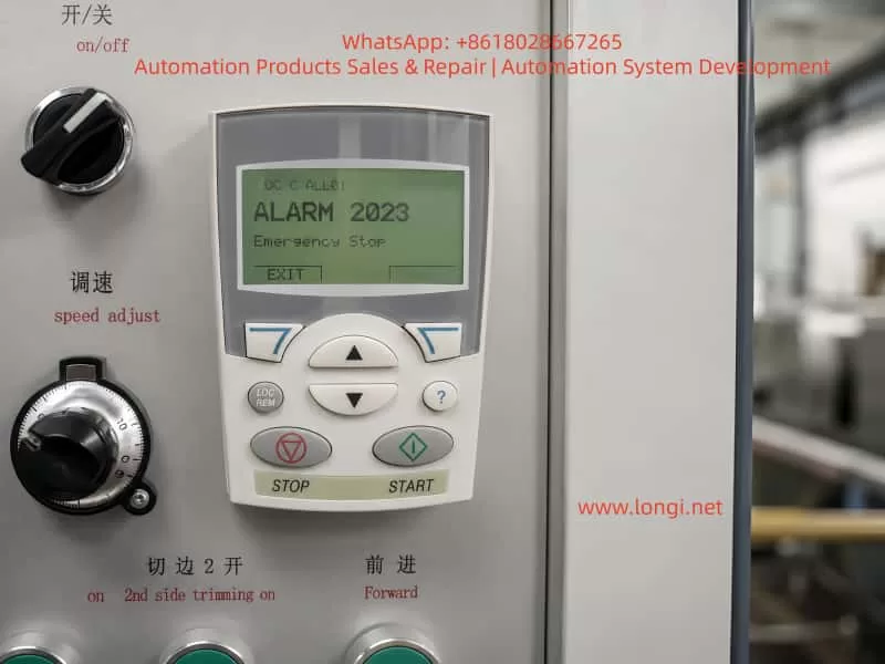
Close-up of an ABB ACS550 drive keypad displaying Alarm 2023 Emergency Stop on an industrial machine control panel.

2. What Alarm 2023 Really Means

Alarm 2023 on an ABB ACS550 indicates that the emergency stop function is active. This is generally a control logic alarm rather than a typical power-stage fault such as overcurrent, DC bus overvoltage, undervoltage, IGBT short circuit, or motor insulation failure.

From a maintenance perspective, the alarm can be understood in three layers.

First, the drive is not allowed to run under the current condition. Even if the START button is pressed, the ACS550 may not output normally.

Second, the drive has detected an external control input state that corresponds to emergency stop, safety stop, or run inhibit.

Third, the root cause is usually found in the control circuit, digital input wiring, parameter setting, or input hardware circuit.

This distinction is very important. If Alarm 2023 appears, replacing the inverter immediately is usually not the correct first step. The external safety chain and input logic must be checked before judging the drive itself as defective.

3. Common Emergency Stop Control Structures on ACS550 Systems

Different machine manufacturers may wire the ACS550 in different ways. However, in industrial equipment, the emergency stop signal usually follows one of the following structures.

3.1 Emergency Stop Button Directly Connected to a Drive Digital Input

In a simple control system, the emergency stop button may be wired directly to one of the ACS550 digital inputs. The button normally uses a normally closed contact. When the emergency stop button is released, the digital input receives the correct signal. When the button is pressed, the circuit opens and the drive stops or reports an emergency stop alarm.

This structure is simple, but it is usually found only on smaller machines or systems with lower safety requirements.

3.2 Emergency Stop Button Connected Through an Intermediate Relay

In many machines, the emergency stop button does not go directly into the drive. Instead, it controls an intermediate relay. The relay output contact then provides a signal to the ACS550 digital input.

In this structure, the emergency stop button may be mechanically normal, but the drive can still receive an emergency stop signal if the relay coil is not energized, the relay contact is oxidized, the relay base is loose, or the wiring between the relay and the drive is damaged.

Therefore, checking only the button is not enough. The relay output contact must also be checked.

3.3 Emergency Stop Circuit Connected Through a Safety Relay

On machines with safety doors, dual-channel emergency stops, safety light curtains, guard switches, or protective covers, the emergency stop circuit usually enters a safety relay or safety controller. Only when the safety relay is reset and all safety channels are valid will the relay output a safety-permit signal to the PLC or the drive.

In this structure, the emergency stop button may already be reset, but the safety relay may still be in a fault or unreset state. The safety relay may require manual reset, dual-channel consistency, correct power-up sequence, or a closed safety door before it enables its output contacts.

When this type of system reports ACS550 Alarm 2023, the safety relay status LEDs must be checked carefully. The technician should verify power, input channels, reset status, output status, and fault indication.

3.4 PLC-Based Emergency Stop and Run-Permit Logic

On more advanced automated equipment, the emergency stop, safety door, thermal relay, air pressure switch, limit switch, and other interlock signals may first enter a PLC. The PLC then processes the machine logic and sends a run-enable or drive-enable signal to the ACS550.

In this case, the ACS550 is only the final actuator in the control chain. Alarm 2023 may appear because the PLC is not providing the run-permit signal. The cause may be a missing sensor condition, PLC program interlock, damaged PLC output, failed intermediate relay, incorrect 24 V signal, or wiring problem.

This is why the alarm must be analyzed as a system-level control issue, not only as a drive issue.

Technician using a multimeter to troubleshoot the emergency stop circuit and safety relay wiring of an ABB ACS550 drive inside an electrical control cabinet.

4. Why Alarm 2023 Can Remain Even When the Emergency Stop Button Is Normal

In many real field cases, the operator confirms that the emergency stop button is not pressed, but the ACS550 still displays Alarm 2023. This can happen for several reasons.

4.1 The Button Is Normal, but the Wiring Is Open

The emergency stop button may mechanically reset correctly, but the cable from the button to the terminal block, relay, PLC, or drive may be broken or loose. Industrial machines are subject to vibration, oil contamination, dust, and repeated maintenance work. Terminal screws may loosen, connectors may oxidize, and cable cores may break inside the insulation.

The correct check is not only to test the button contact. The signal must be traced all the way to the ACS550 digital input terminal.

4.2 The Safety Relay or Emergency Stop Relay Has Not Reset

After the emergency stop button is released, the safety relay may still remain in a tripped state. Some safety relays require a separate reset signal. Some require both safety channels to recover simultaneously. Some will not reset if one safety door or guard switch is still open.

If the safety relay output is not enabled, the ACS550 will not receive the correct permit signal, and Alarm 2023 may remain.

4.3 The 24 V Control Supply Is Missing or Abnormal

ACS550 digital inputs require a valid control voltage and reference. Depending on the machine design, the digital input signal may come from the drive’s internal 24 V supply, an external 24 VDC power supply, a PLC output, or an intermediate relay.

If the 24 V control supply is missing, weak, unstable, or if the 0 V reference is disconnected, the digital input state may become invalid. The operator may see that buttons and switches look normal, but electrically the ACS550 is not receiving the proper input level.

4.4 The Digital Input Common Terminal Is Incorrectly Wired

Digital inputs require both the input signal and the correct common reference. If the DI common, DCOM, COM, 0 V, or 24 V wiring is incorrect, the drive may not recognize the input even though voltage appears to be present somewhere in the control cabinet.

This problem is common after drive replacement, control cabinet rewiring, terminal strip repair, or parameter restoration. A technician may reconnect the signal wire but forget the correct common reference.

4.5 Parameters Have Been Changed

If ACS550 parameters have been changed, a digital input may have been assigned to emergency stop, run enable, start enable, or external fault. If the selected digital input is not wired correctly, the drive may continuously detect an invalid condition.

This is especially common when a second-hand drive is installed, a replacement drive is used, factory reset has been performed, or multiple people have adjusted the drive parameters.

For example, if an unused DI terminal is accidentally assigned as an emergency stop input, the drive may remain in Alarm 2023 because that DI never receives the required signal.

4.6 The ACS550 Digital Input Circuit Is Damaged

If the external circuit, voltage, relay contacts, common terminal, and parameter configuration are all confirmed to be correct, but the ACS550 input status still does not change, the digital input circuit may be damaged.

Possible causes include incorrect high-voltage wiring into a low-voltage input, short circuit, surge voltage, moisture contamination, terminal corrosion, damaged optocoupler, or failure in the control board input circuit.

This diagnosis should only be made after the external control signal has been fully verified at the drive terminals.

5. Correct Field Troubleshooting Sequence

The most efficient way to troubleshoot ACS550 Alarm 2023 is to work from outside to inside, from simple checks to detailed electrical verification, and from signal status to parameter logic.

Step 1: Confirm All Emergency Stop and Safety Devices

Check all emergency stop buttons on the machine, not only the one near the main control panel. Some machines have multiple emergency stops at different locations, including remote stations, conveyor ends, control cabinet doors, and operator stations.

Also check safety doors, guard switches, limit switches, safety light curtains, protective covers, pull-wire emergency switches, and thermal overload contacts.

A single open safety device can keep the ACS550 in emergency stop status.

Step 2: Check the Safety Relay or Intermediate Relay

Open the control cabinet and check whether the emergency stop relay, safety relay, or intermediate relay is energized.

If the relay has LED indicators, check the power indicator, input channel indicators, reset status, output indicators, and fault indication.

If the relay is not energized, measure the coil voltage. If the coil has no voltage, the upstream safety circuit is not complete. If the coil has correct voltage but the relay does not operate, the relay itself may be faulty. If the relay operates but its output contact does not close, the contact may be damaged or oxidized.

Step 3: Measure the ACS550 Digital Input Terminal Voltage

This is one of the most important steps. Identify which ACS550 digital input is assigned to emergency stop, run enable, or start enable. Then use a multimeter to measure the voltage between that DI terminal and the correct common terminal.

When the emergency stop circuit is reset, the input should have the correct valid level according to the drive configuration. When the emergency stop is pressed, the input state should change.

If the external device operates but the voltage at the ACS550 terminal does not change, the fault is in the external wiring or relay circuit.

If the voltage at the ACS550 terminal changes correctly but the drive input status does not change, the problem may be in the drive input circuit, common wiring, or parameter configuration.

Step 4: Check the ACS550 I/O Status on the Keypad

The ACS550 keypad can be used to view digital input status. The technician should check the ON/OFF status of DI1, DI2, DI3, DI4, DI5, and DI6.

This step is essential because measuring voltage at the terminal and confirming that the drive internally recognizes the input are not the same thing. The drive must actually detect the input state change.

If the emergency stop circuit is reset and the corresponding DI does not change to the expected state, the drive is still not receiving or recognizing the correct signal.

Step 5: Verify Parameter Configuration

If the digital input voltage and keypad I/O status appear normal but the alarm remains, the relevant parameters must be checked.

The technician should review parameters related to control macro, external command source, digital input assignment, emergency stop, run enable, start enable, external fault, and input polarity.

Parameter checking must be done carefully. The original parameters should be recorded before any changes are made. If possible, compare the settings with the machine electrical drawing, commissioning record, or another identical machine.

Blindly disabling emergency stop or run-enable functions is not an acceptable repair method.

Step 6: Evaluate Possible Drive Control Board or Input Damage

Only after external wiring, control voltage, relay contacts, common terminal, and parameter configuration have been confirmed should the technician consider a faulty ACS550 control board or digital input circuit.

Further verification may include assigning the function to another spare DI input, testing the same signal on another input, comparing with an identical drive, or inspecting the control board input components.

Any temporary reassignment of a safety-related input must be done by qualified personnel and must not compromise machine safety.

6. Important Measurement Notes

6.1 Do Not Measure Only the Button

Testing the emergency stop button alone is not enough. The drive does not know whether the button itself is good. The drive only knows whether the correct signal reaches its digital input.

Therefore, the signal must be traced from the button to the relay, from the relay to the terminal block, from the terminal block to the PLC or drive, and finally to the ACS550 DI terminal.

6.2 Pay Attention to Normally Open and Normally Closed Logic

Emergency stop circuits usually use normally closed contacts. In normal condition, the circuit is closed. When the emergency stop is pressed, the circuit opens.

However, the drive parameter logic may define whether an input is active high or active low. If the wiring logic and parameter logic do not match, the drive may interpret a normal condition as an emergency stop condition.

This type of logic mismatch is common after parameter changes or drive replacement.

6.3 Confirm the Source of the 24 V Signal

Some machines use the ACS550 internal 24 V supply for digital inputs. Others use an external 24 VDC power supply or PLC output. Before testing or shorting any input, the technician must confirm where the 24 V signal comes from.

Incorrectly mixing an external 24 V supply with the drive’s internal 24 V supply may damage the drive control terminal or PLC output.

6.4 Do Not Bypass the Emergency Stop Circuit Permanently

Some technicians may temporarily short the emergency stop input to make the drive run. This may help identify the fault range, but it creates a serious safety risk.

Emergency stop circuits protect personnel and equipment. On machines with cutters, conveyors, winders, fans, presses, or moving mechanisms, bypassing emergency stop protection can cause injury or equipment damage.

If a temporary bypass is required for diagnosis, it must be performed only under controlled conditions, with the mechanical load isolated, personnel kept away from moving parts, and the original safety circuit restored immediately after testing.

7. Typical Field Case Analysis

A machine using an ABB ACS550 cannot start. The keypad displays Alarm 2023 Emergency Stop. The operator checks the emergency stop button on the control panel and confirms that it is not pressed. The button is rotated and reset several times, but the alarm remains.

At this point, it would be incorrect to conclude immediately that the inverter is damaged. The better approach is to inspect the complete safety chain.

After opening the control cabinet, the technician may find that the emergency stop button does not connect directly to the drive. Instead, it enters a safety relay first. The safety relay output goes to the PLC, and the PLC outputs a run-permit signal to one digital input of the ACS550.

This means that the ACS550 alarm does not necessarily indicate a defective emergency stop button. It indicates that the final run-permit signal has not reached or has not been recognized by the drive.

Possible findings include:

The safety relay has not reset.
The safety relay output contact is not closed.
The PLC has not received the safety relay feedback.
The PLC does not output the run-permit signal.
The intermediate relay contact between the PLC and ACS550 is oxidized.
The ACS550 DI terminal wire is loose.
The 24 V supply is normal, but the DCOM common wire is open.
A parameter has been changed, assigning emergency stop to an unwired DI terminal.

By analyzing the signal chain in this way, the technician can avoid unnecessary drive replacement and locate the real control-circuit fault more efficiently.

8. Difference Between Alarm 2023 and Other Start-Inhibit Alarms

On the ACS550, there are several alarms and conditions that may prevent the drive from starting. These include emergency stop, start enable missing, run enable missing, external fault, and other interlock-related conditions.

Although the symptom may be similar, the causes are different.

Emergency Stop indicates that the emergency stop or safety stop function is active.
Start Enable missing usually indicates that a start-permission input is not satisfied.
External Fault indicates that an external device is reporting a fault to the drive through a digital input.
Run Enable problems indicate that the drive’s run-permit condition is not met.

Therefore, troubleshooting must be based on the exact alarm code and message shown on the keypad. Not all “drive cannot start” cases should be treated as the same fault.

For Alarm 2023, the key point is that the drive believes the emergency stop state is active. If the physical button is not pressed, the next focus should be the safety relay, PLC logic, digital input status, 24 V supply, common terminal, and parameter assignment.

9. Recommended Diagnostic Logic for Technicians

When dealing with ACS550 Alarm 2023, technicians should follow a clear diagnostic logic.

First, do not immediately assume that the drive is damaged. Alarm 2023 is more likely related to external control signals than to the power section.

Second, do not rely only on the visual condition of the emergency stop button. A released button does not guarantee that the ACS550 has received the correct safety-permit signal.

Third, focus on the digital input assigned to emergency stop or run enable. Once this DI point is identified, the technician can determine whether the problem is outside the drive or inside the drive.

Fourth, combine voltage measurement with keypad I/O status. If voltage is missing at the terminal, the problem is external. If voltage is present but the drive input status does not change, the problem may be in the input circuit, common wiring, or parameter logic.

Fifth, check parameters carefully. Parameter errors can create a false emergency stop condition. However, safety-related functions should not be disabled casually.

Sixth, never use a permanent bypass as a repair solution. Emergency stop is part of the machine safety system and must be restored before normal operation.

10. Practical Field Checklist

The following checklist can be used during troubleshooting:

  1. Confirm that all emergency stop buttons are fully reset.
  2. Check safety doors, covers, guard switches, light curtains, and limit switches.
  3. Check whether the emergency stop relay or safety relay is energized.
  4. Confirm whether the safety relay requires manual reset.
  5. Measure the 24 V control supply.
  6. Check 0 V, DCOM, COM, and digital input common wiring.
  7. Measure the voltage at the relevant ACS550 DI terminal.
  8. Check whether the corresponding DI status changes on the keypad.
  9. Review parameters related to emergency stop, start enable, run enable, external fault, and control macro.
  10. Confirm whether the drive has been replaced, reset, or reprogrammed recently.
  11. Check whether the PLC is outputting the run-permit signal.
  12. Inspect intermediate relay contacts for oxidation or poor contact.
  13. Check terminal blocks, connectors, cable numbers, and wiring tightness.
  14. If all external signals are correct, evaluate possible ACS550 digital input or control board damage.

This checklist helps narrow the fault from the complete safety circuit to the exact drive input point.

11. Maintenance Conclusion

ABB ACS550 Alarm 2023 “Emergency Stop” means that the drive has detected an active emergency stop or safety stop condition. In most cases, the root cause is not a damaged inverter power stage, but an issue in the external emergency stop chain, safety relay, PLC interlock, 24 V control supply, digital input wiring, common terminal, parameter logic, or the drive’s digital input circuit.

When the emergency stop button appears normal, the emergency stop circuit should not be considered fully cleared. The key question is whether the correct reset or run-permit signal has actually reached the ACS550 digital input and whether the drive has recognized it through its I/O status.

If there is no correct voltage at the ACS550 DI terminal, the fault is usually in the external control circuit. If the terminal voltage is correct but the drive input status does not change, the cause may be incorrect common wiring, input circuit failure, or control board damage. If the input status is correct but the alarm remains, parameter logic and run interlock configuration should be checked carefully.

The correct troubleshooting strategy is to trace the signal step by step, verify the digital input status, confirm the parameter assignment, and only then judge whether the drive itself is faulty. Blindly replacing the drive or bypassing the emergency stop circuit may create unnecessary cost and serious safety risk.

A safe and reliable repair requires both electrical diagnosis and respect for the machine safety system. Only after the external safety chain, ACS550 input status, and parameter logic are fully verified can Alarm 2023 be resolved accurately and the equipment returned to stable operation.

Posted on

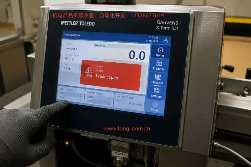
Analysis of Garvens X-Terminal-IPC Industrial HMI Unresponsiveness: From Touchscreen Failure to Remote IPC Diagnostics

In automated checkweighers, dynamic weighing systems, packaging inspection lines, and metal detection integration systems, Mettler Toledo Garvens devices often utilize industrial PCs (IPC) paired with HMI terminals as the core human-machine interface. Operators rely on touchscreens to select products, load recipes, manage batch operations, view weighing data, configure reject settings, and acknowledge alarms. When an HMI becomes unresponsive, even if the device continues to run in the background, production line operators lose control, which can lead to full line stoppages.

One common misdiagnosed fault involves the following situation: the screen displays normally, but the touchscreen does not respond; when an external USB mouse is connected to the IPC, it also fails to control the interface; power cycling does not resolve the issue; however, the IPC’s Ethernet port LEDs continue blinking, and the IPC’s IP address can be detected using network scanning tools. At first glance, this may appear to be a “touchscreen failure,” but from a maintenance perspective, the issue is often not confined to the HMI touchscreen itself. Instead, the root causes may involve the IPC operating system, USB/HID input chain, touchscreen controller, Windows services, Garvens HMI software, or the IPC motherboard hardware.

This article provides a detailed examination of such faults in Garvens X-Terminal-IPC industrial terminals, outlining diagnosis methods, remote access possibilities, port scanning procedures, on-site emergency handling, and key considerations for repair.


Close-up of a Mettler Toledo Garvens X-Terminal industrial touchscreen panel in a factory environment, displaying a red error message 'E-004 Product jam', with a gloved hand pointing at the screen and cables visible around the stainless steel enclosure.

1. Differences Between Garvens X-Terminal-IPC and Standard HMI

Many technicians assume a device with a touchscreen is a simple HMI. However, in Garvens and Mettler Toledo systems, some terminals are not conventional embedded HMIs but industrial PC-based HMIs.

Standard embedded HMIs typically run proprietary firmware; interface programs are downloaded directly onto the HMI device, and communications occur primarily with PLCs, weighing controllers, or drives. In contrast, X-Terminal-IPC devices have these characteristics:

  1. They may run Windows or Embedded Windows operating systems internally.
  2. They include an Ethernet port for connecting to weighing controllers, production networks, or remote service tools.
  3. They include USB ports for mice, keyboards, backup media, or maintenance devices.
  4. They have COM ports for connecting older controllers or external modules.
  5. They are powered by a 24VDC industrial power supply.
  6. The system drive stores HMI software, device parameters, recipes, communication configurations, and historical data.

Consequently, when such devices become unresponsive, conventional HMI repair methods are insufficient. It is critical not to reinstall Windows, reset the system, or replace the disk without first backing up the system drive, as this may result in loss of proprietary software and device configurations.


2. Typical Fault Symptoms

Common field symptoms include:

  • The display remains active, indicating that the LCD and backlight are operational and video output is at least partially functional.
  • Touch inputs on the screen do not respond.
  • External USB mice connected to USB1 or USB2 also fail.
  • Power cycling does not restore functionality.
  • Ethernet LEDs continue blinking.
  • Using a laptop with an IP scanner, the IPC and the associated weighing controller IP addresses are detected, and the IPC can be pinged.

This combination of symptoms is critical: local input is nonfunctional, but network connectivity is still active.

This suggests that the IPC is not entirely dead; at minimum, the network interface, TCP/IP stack, or underlying system processes are still running. Meanwhile, the local touchscreen, USB input, or HMI software may be malfunctioning.


Technician wearing a white safety helmet and protective workwear troubleshooting a Mettler Toledo Garvens X-Terminal IPC, adjusting cables and connections while monitoring a laptop connected to the industrial terminal inside a factory setting.

3. Why It Should Not Be Assumed to Be a Touchscreen Failure

If the problem were solely the touchscreen glass, the USB mouse should still allow control of the interface. Users would be able to navigate the HMI software menus or reset alarms.

However, if both the touchscreen and external USB mouse fail, the fault range is significantly broader. The likely causes include:

  1. IPC system freeze: Windows GUI or HMI software may be frozen, while the network stack continues responding to pings.
  2. USB/HID driver issues: touch and external devices may not be recognized due to driver or service errors.
  3. IPC motherboard USB controller failure: multiple USB ports nonfunctional, keyboard LEDs unresponsive.
  4. Internal touchscreen controller fault: short circuits or errors on the internal USB line may prevent any USB device from working.
  5. HMI software abnormal behavior: industrial software may lock the interface during critical alarms or communication errors.

The correct conclusion is that the fault is primarily on the IPC side, not just the touchscreen. While touchscreen hardware cannot be fully excluded, the focus of diagnostics should be IPC system operation, USB/HID input, motherboard interfaces, and remote accessibility.


4. What Ping Availability Indicates—and What It Does Not

Many assume that a successful ping means the IPC is fully operational, which is incorrect.

A ping indicates:

  1. Ethernet hardware is powered and connected.
  2. The IPC IP is reachable.
  3. Some system or network service is responding to ICMP requests.

A ping does not indicate:

  1. Windows desktop or HMI software is operational.
  2. USB input is functional.
  3. Touch drivers are working.
  4. Remote desktop or VNC services are enabled.
  5. Applications are stable and running correctly.

Therefore, ping success only indicates the IPC is not completely offline. Further diagnostics are required to determine if it can be remotely controlled.


5. Why Web Access May Fail

Some IPCs provide web interfaces, but a browser failing to access the IPC IP does not imply the IPC is offline. Many X-Terminal-IPC devices do not have HTTP services enabled by default. Web access failure could simply indicate that ports 80 or 8080 are closed.

Remote access options for industrial IPCs generally include:

  1. Windows Remote Desktop (RDP, port 3389)
  2. VNC (port 5900)
  3. Proprietary Garvens maintenance software
  4. Windows file sharing (SMB, port 445)
  5. Industrial software communication ports
  6. FTP or SSH (less common on Windows IPCs)

Thus, a browser test alone is insufficient for fault diagnosis.


6. FreeWeigh.Net Is Not Equivalent to IPC Remote Maintenance

FreeWeigh.Net is Mettler Toledo’s statistical quality control and production data management software. It is used for data acquisition, SPC/SQC, batch management, and communication with weighing/checkweigher devices.

However, FreeWeigh.Net does not provide remote control of the IPC desktop, and installing it will not restore touchscreen or USB mouse functionality. It is a data management tool, not a maintenance or recovery utility.

The priority in this fault scenario is to determine if the IPC offers any remote access channels.


7. Purpose of Port Scanning

Port scanning identifies which legitimate services are available on the IPC. For industrial maintenance, this is essential.

  • Port 3389: Windows Remote Desktop
  • Port 5900: VNC
  • Ports 80/8080: Web services
  • Port 445: SMB file sharing

If none of these ports are open, remote desktop control is not available, and the device cannot be managed through Ethernet alone.


8. PowerShell Port Testing

For technicians unfamiliar with Nmap, Windows PowerShell can test critical ports:

Test-NetConnection 172.21.177.220 -Port 3389
Test-NetConnection 172.21.177.220 -Port 5900
Test-NetConnection 172.21.177.220 -Port 80
Test-NetConnection 172.21.177.220 -Port 8080
Test-NetConnection 172.21.177.220 -Port 445
  • TcpTestSucceeded: True indicates the port is reachable.
  • False indicates the port is closed, firewall-blocked, or unreachable.

9. Nmap Port Scanning

For comprehensive scanning, Nmap can enumerate all open TCP ports:

nmap -Pn -sV 172.21.177.220
  • -Pn: skip host discovery.
  • -sV: attempt service/version detection.
  • Scan all TCP ports: nmap -Pn -p- 172.21.177.220

Open ports will guide remote access attempts.


10. Remote Desktop Access

If port 3389 is open, launch Remote Desktop (mstsc), enter the IPC IP, and log in using the correct Windows credentials. Success allows viewing the desktop, checking device manager, USB drivers, and HMI software.


11. VNC Access

If port 5900 is open, VNC Viewer can connect. Advantages:

  1. Directly mirrors HMI interface.
  2. Can interact even if local touch/mouse fail.
  3. Enables process recovery and configuration backup.

12. USB Keyboard Testing

Testing a USB keyboard is crucial:

  • Plug in a wired USB keyboard.
  • Check Num Lock/Caps Lock LEDs.
  • Try Ctrl+Alt+Del, Alt+Tab, Alt+F4, Windows key.
  • LEDs responding suggests USB controller may still work.
  • No response indicates USB/HID controller or motherboard problem.

13. On-Site Emergency Procedure

  1. Document device label, model, serial number, software version, wiring photos.
  2. Measure 24VDC supply.
  3. Fully power down for 1–2 minutes.
  4. Test touch, USB mouse, and keyboard.
  5. Check Ethernet LED.
  6. Scan IP and ping.
  7. Perform port scan.
  8. Attempt RDP or VNC.
  9. Backup configurations and system files if remote access succeeds.
  10. If remote fails and local input is dead, backup system drive before any repair.

14. System Drive Backup Importance

Garvens IPC system drives store:

  • HMI software
  • Device configurations
  • Communication parameters
  • Product recipes
  • Reject logic
  • Language packs
  • User permissions
  • Database files
  • Historical logs
  • Licenses and authorization
  • Network and COM settings
  • Touch calibration data

Backup prevents permanent loss during repairs.


15. Probable Root Causes

  1. IPC system or HMI software freeze
  2. USB/HID driver malfunction
  3. IPC motherboard USB controller failure
  4. Touch controller short affecting USB bus
  5. 24V power instability
  6. System drive corruption or aging

16. Common Mistakes to Avoid

  • Replacing touchscreen blindly
  • Reinstalling Windows without backup
  • Resetting to factory defaults
  • Changing IP addresses incorrectly
  • Relying solely on browser access
  • Ignoring 24V power quality
  • Replacing system disk before imaging

17. Recommended Repair Workflow

  1. Document device info and wiring
  2. Check power
  3. Power cycle
  4. Test USB input devices
  5. Verify Ethernet
  6. IP scan
  7. Ping IPC
  8. Port scan
  9. Remote access attempts
  10. Backup all important data
  11. Inspect drivers, device manager, events
  12. If remote fails, backup system disk
  13. Inspect IPC motherboard, USB, touch controller
  14. Repair or replace IPC as needed
  15. Restore system image

18. Conclusion

When a Garvens X-Terminal-IPC exhibits unresponsive touchscreen, unresponsive USB mouse, fails to recover on power cycle, but Ethernet LEDs blink and IP responds to ping, the fault should not be simplistically attributed to the touchscreen. Instead, the problem is likely on the IPC side: local input, USB/HID, Windows, HMI software, or motherboard.

Ping success indicates partial system availability but does not guarantee control. Port scanning is essential to identify potential remote access via RDP, VNC, web, or SMB. Remote access allows configuration backup and recovery. If no remote path exists and local input fails, system disk imaging is critical before attempting hardware repair.

In such industrial environments, the IPC is not merely a display; it is the core node of HMI and production data management. Proper diagnostics, cautious handling of system drives, and structured repair workflow are essential to restore functionality while preserving critical device data.

Posted on

Analysis, Diagnosis, and Repair of Yaskawa SERVOPACK A.923 Fault

1. Overview of the Fault

During operation of Yaskawa SERVOPACK servo drives, operators may encounter the A.923 code displayed on the drive panel. This fault is commonly observed in the Sigma series, particularly when the device is running continuously, the control cabinet temperature is high, dust accumulation is significant, or the drive has been in service for an extended period.

The core meaning of A.923 is: the built-in cooling fan in the SERVOPACK has stopped or is operating abnormally. It is a fan-stop warning, not a motor, encoder, overcurrent, or main power circuit failure. Essentially, the servo drive has detected that the internal fan is not operating according to its specifications and is alerting the operator.

Although A.923 does not indicate an immediate catastrophic failure, it should not be ignored. The internal components of the servo drive—including rectifiers, DC bus capacitors, IGBT modules, braking units, power supplies, driver circuits, and control boards—generate heat during operation. If the fan stops, internal temperatures rise, potentially causing overheat alarms, sudden shutdowns, capacitor aging, IGBT module damage, and, in extreme cases, complete power section failure.

Thus, when A.923 occurs, the root cause should be investigated from multiple angles: fan condition, fan power supply, fan signal feedback, duct and cabinet environment, control board detection circuits, and overall cooling conditions.

Close-up view of a Yaskawa Σ-7 SERVOPACK inside an industrial electronics enclosure, showing a red A.923 error code on the display, surrounded by connectors, colorful wires, and a cooling fan, highlighting the internal components of the servo drive.

2. Technical Meaning of A.923

The primary function of the internal fan is to force airflow to dissipate heat from power devices. Medium- and high-power SERVOPACK drives cannot rely solely on natural convection, and the fan ensures effective heat removal from heatsinks, power modules, and the drive enclosure.

A.923 indicates the drive has detected abnormal fan operation. Scenarios include:

  1. Fan completely stopped: On power-up, the fan does not rotate or stops mid-operation.
  2. Fan speed too low: Bearing wear, dust, or blade resistance causes reduced rotation speed. The drive may detect this as abnormal.
  3. Intermittent fan stoppage: Loose connections, broken wiring, or internal fan sensor issues cause the fan to stop sporadically.
  4. Fan rotating but detection signal abnormal: Fan power is fine, but rotation feedback (e.g., FG signal) is missing or incorrect.
  5. Control board detection circuit failure: Even with a working fan, a damaged detection circuit may falsely trigger A.923.

3. Impact on Equipment Operation

A.923 primarily affects the drive’s cooling. Many operators assume that as long as the drive runs, the alarm can be ignored; this is risky.

IGBT modules and DC bus capacitors generate significant heat, especially during frequent acceleration/deceleration. Without fan cooling, heat accumulates, potentially triggering overheat alarms, power module failure, or DC bus capacitor degradation.

Extended operation under A.923 may shorten capacitor life, reduce ripple tolerance, and destabilize power supplies. In production lines, a drive shutdown can halt the entire process, damage materials, or cause mechanical jamming. Therefore, A.923 is a reliability warning that requires timely attention.

High-resolution macro shot of a Yaskawa Σ-7 SERVOPACK showing the A.923 alarm, with detailed view of the internal wiring, connectors, and a large cooling fan within a tidy industrial control cabinet.

4. Common Causes of A.923

4.1 Fan Failure

Bearings wear over time, lubrication declines, and blades experience resistance. Dusty, oily, or high-temperature environments accelerate deterioration.

4.2 Fan Obstruction

Dust, debris, wire ends, or foreign objects can block the fan blade or heatsink, increasing load or stopping rotation.

4.3 Loose Connectors or Wiring

Vibration or maintenance can loosen fan plugs or wires, causing intermittent operation.

4.4 Fan Power Supply Issue

Fans require DC12V or DC24V. Supply failure prevents operation.

4.5 Feedback Signal Abnormal

Fans with FG signals may rotate correctly but fail to provide feedback, causing the drive to detect a fault.

4.6 Control Board Detection Circuit Fault

Damaged board circuits may misinterpret signals or fail to detect fan rotation.

4.7 Poor Cabinet Cooling

Clogged filters, poor ventilation, insufficient spacing, or crowded drives can reduce cooling efficiency and indirectly trigger A.923.

5. On-Site Troubleshooting Procedure

  1. Confirm the alarm code: Ensure the display shows A.923.
  2. Observe fan operation: Safely power up and check if the fan rotates.
  3. Power off and discharge: Wait for DC bus voltage to drop.
  4. Inspect mechanical condition: Check blade smoothness, wear, and obstruction.
  5. Check fan power supply: Measure voltage per fan specifications.
  6. Replace with a compatible fan: Match voltage, feedback type, wiring, and airflow direction.
  7. Check detection signals: Ensure FG or other feedback lines function.
  8. Clear the alarm and test: Verify fan operation and drive temperature under load.

6. Repair Recommendations

For most maintenance personnel:

  • Clean dust and debris.
  • Check connectors and wiring.
  • Replace the fan with the correct specification.
  • If the alarm persists, inspect fan power supply and control board circuits.

Do not ignore A.923. Continuing operation increases the risk of overheat, shutdown, and component failure.

7. Common Misdiagnoses

  • Confusing A.923 with motor or encoder failure.
  • Assuming a visibly spinning fan is always normal.
  • Using a physically similar but electrically incompatible fan.
  • Only replacing the fan without cleaning the duct or enclosure.
  • Continuing operation without intervention.

8. Preventive Maintenance

  • Periodically clean filters and enclosures.
  • Inspect fan noise and speed.
  • Replace aged fans proactively.
  • Ensure sufficient cabinet ventilation and spacing.
  • Protect against moisture, oil, and conductive dust.

9. Customer Guidance

Inform customers:

A.923 indicates the internal cooling fan has stopped or has abnormal feedback. It is not a motor or encoder fault. Immediate action is recommended to inspect the fan, clean the duct, and replace the fan if necessary. Persistent alarms may indicate internal drive circuits need repair.

This approach clarifies the issue while avoiding unnecessary concern about motor or drive failure.

10. Conclusion

A.923 is a preventive warning about the cooling system in a Yaskawa SERVOPACK. Proper diagnosis includes verifying fan operation, power supply, feedback, and detection circuits. Most cases involve fan wear, obstruction, loose wiring, or power supply issues. Ignoring A.923 risks overheating, shutdown, and power module damage. Timely intervention ensures stable drive operation and long-term reliability.

Posted on

Delta C2000 Series Inverter VFDr Fault Analysis: Causes, Diagnosis, and Repair Logic for “Read VFD Info Error”

1. Overview of the Fault Symptom

During the maintenance and commissioning of Delta C2000 series inverters, technicians may occasionally encounter a fault message on the keypad display showing “VFDr / Read VFD Info Er”. At first glance, this fault does not resemble common inverter faults such as overcurrent, overvoltage, undervoltage, overload, phase loss, ground fault, or overheating. Instead, it points more toward an internal communication or data-reading problem.

Taking a Delta C2000 inverter model VFD040C43A-21 as an example, this unit belongs to the three-phase 380–480V input class, with an output power of approximately 4kW / 5HP. After power-up, the keypad lights up normally, but the display shows:

Fault
VFDr
Read VFD Info Er

From the literal meaning, VFDr can be understood as an abnormal condition during the keypad’s reading of VFD information. The English message “Read VFD Info Er” means “Read VFD Info Error”, indicating that the keypad has failed to read the inverter’s internal information correctly.

The key point of this fault is that the keypad, control board, memory, communication interface, or low-voltage control power supply may have a data exchange problem. As a result, the keypad cannot correctly read the inverter model, parameter information, status data, or internal identification information.

Therefore, the VFDr fault should not be simply understood as a damaged power module, nor should it be directly classified as a motor-side fault. It is more accurately described as an information-reading failure between the human-machine interface and the inverter control system. During repair, troubleshooting should focus first on the keypad, keypad connector, control board communication circuit, low-voltage power supply, memory devices, and the general condition of the control board.

Delta C2000 series inverter showing VFDr fault and “Read VFD Info Er” message on the keypad display during workshop diagnosis.

2. Essential Meaning of the VFDr Fault

The keypad of an inverter is not merely a simple display screen. It usually performs several functions:

It displays operating frequency, current, voltage, fault codes, and status information. It allows parameter reading and modification. It executes commands such as start, stop, forward/reverse operation, and reset. It exchanges data with the main control board through a communication interface. During power-up, it reads the inverter model, capacity, firmware version, parameter area, status flags, and other internal information.

When the keypad displays “Read VFD Info Er”, it means that the keypad has failed while reading internal information from the inverter. This failure may occur at several levels.

The keypad itself may not be working properly. The connection between the keypad and the inverter control board may be poor. The control board may not be responding correctly to the keypad’s request. The internal memory data on the control board may be abnormal, causing the keypad to read invalid information. The low-voltage control power supply may be unstable, causing the MCU, memory, or communication IC to operate abnormally. The control board may be affected by moisture, oxidation, contamination, cold solder joints, or connector damage, resulting in communication failure.

From a repair perspective, VFDr is a communication and data-reading fault, not a typical power output fault. This distinction is very important. If the fault is incorrectly judged as an IGBT, rectifier bridge, DC bus capacitor, or driver board failure, the repair direction will be wrong and a great deal of time may be wasted.

3. Basic Structure of the Delta C2000 Inverter

To analyze the VFDr fault accurately, it is necessary to understand the basic electrical structure of the C2000 series inverter. In general, an inverter consists of the following sections.

3.1 Main Power Circuit

The main power circuit includes the input rectifier, DC bus, pre-charge circuit, braking unit, inverter IGBT module, current detection circuit, and output terminals. Its function is to rectify three-phase AC power into DC power, then use the IGBT inverter section to output three-phase AC power with adjustable frequency and voltage.

Common main circuit faults include input phase loss, DC bus overvoltage, DC bus undervoltage, IGBT short circuit, output ground fault, output phase loss, and braking unit faults. These faults usually appear as protection-related codes such as OC, OV, LV, GF, OH, or OL.

VFDr does not usually point first to a main power circuit fault. Even if the power board is damaged, it may not directly cause VFDr. Conversely, even if the power section is normal, the inverter may still display VFDr due to abnormal communication, memory failure, or control board problems.

3.2 Control Power Supply

The control power supply usually generates several low-voltage rails through a switching power supply circuit, such as 24V, 15V, 5V, and 3.3V. The exact voltage configuration may vary by model, but the general functions are as follows.

The 24V supply is often used for relays, external terminals, fan control, or interface circuits. The 15V supply may be used for analog circuits, driver front-end circuits, or operational amplifiers. The 5V supply is commonly used for communication ICs, digital logic, and some interface circuits. The 3.3V supply is often used for the main MCU, DSP, Flash, EEPROM, or logic chips.

If the 5V or 3.3V supply is unstable, communication between the keypad and the control board may fail. Slight ripple, a low voltage level, or abnormal power-on reset timing may all cause data-reading errors. During repair, it is not enough to check only whether voltage is present. The technician should also confirm whether the voltage is stable, whether ripple is excessive, and whether the power-up sequence is normal.

3.3 Main Control Board

The main control board is the brain of the inverter. It handles parameter processing, operation logic, fault protection, PWM output, communication management, and keypad interaction. It usually contains an MCU or DSP, memory devices, communication ICs, crystal oscillator, reset circuit, analog sampling circuits, and digital input/output circuits.

The VFDr fault is closely related to the control board. If the control board cannot return correct device information to the keypad, the keypad will report a reading error. Control board abnormalities may be caused by several factors:

The MCU fails to start correctly. The crystal oscillator does not oscillate or has an abnormal frequency. The reset circuit is abnormal. Flash or EEPROM data is damaged. The communication IC is faulty. Interface protection components are shorted. The low-voltage power supply is abnormal. The board is affected by moisture or corrosion. The program area or parameter area is corrupted.

3.4 Keypad and Interface Section

The keypad is connected to the inverter body through pins, a ribbon cable, an RJ45 connector, or a similar interface. The keypad usually contains its own MCU, key scanning circuit, display driver, communication interface, and sometimes memory-related devices. It is not a passive display; it is a small communication terminal.

If the keypad connector is oxidized, has poor contact, bent pins, a broken ribbon cable, or a loose socket, VFDr may occur. The same fault may also occur if the keypad’s internal communication IC is damaged. This is especially common in second-hand units, equipment stored for a long time, devices exposed to moisture, or machines used in dusty industrial environments.

Technician testing a Delta C2000 inverter control board with a multimeter while diagnosing the VFDr keypad communication fault.

4. Difference Between VFDr and Common Operating Faults

When technicians see an inverter fault, they may immediately think of the motor, load, IGBT, or power module. However, the logic for diagnosing VFDr is different.

4.1 Common Operating Faults Are Usually Related to Load or Power Circuit Conditions

For example, an overcurrent fault normally requires checking motor insulation, output short circuit, acceleration time, mechanical load jam, IGBT condition, and current detection circuits. An overvoltage fault requires checking input voltage, deceleration time, braking resistor, and braking unit. An overheating fault requires checking the fan, heat sink, temperature sensor, and ambient temperature.

These faults usually occur during start-up, acceleration, operation, deceleration, or load changes.

4.2 VFDr Usually Occurs During Power-Up or Information Reading

VFDr often appears immediately after the inverter is powered on, or when the keypad attempts to enter a menu or read internal information. It is not directly related to whether the motor is connected or whether the load is running. Even if no motor is connected, the inverter may still display VFDr.

This indicates that the fault is closer to the control layer rather than the output power layer.

4.3 VFDr Is Not Simply a Parameter Error

Some technicians may see “Read VFD Info Error” and assume that the parameters are incorrect, then try to restore factory settings. In reality, when the keypad cannot correctly read inverter information, forced initialization may not be effective. The problem may not be parameter setting error; the real issue may be that the keypad cannot establish reliable communication with the control board, or the control board cannot correctly read its own internal information.

If the control board memory is damaged, the communication link is abnormal, or the low-voltage power supply is unstable, restoring parameters will not solve the root cause.

5. Possible Causes of the VFDr Fault

5.1 Poor Keypad Contact

This is one of the most common and easiest causes to eliminate. Industrial environments are complex. After long-term operation, the keypad interface may become oxidized, loose, deformed, or contaminated with dust. After transportation, disassembly, or maintenance, the keypad may also be improperly seated.

The correct method is to power off the inverter, remove the keypad, and inspect the connector and pins for oxidation, blackening, bending, breakage, or looseness. The connector may be cleaned using electronic contact cleaner, then dried thoroughly before reinstallation. If available, a known-good keypad from the same series should be used for cross-testing.

If replacing the keypad clears the fault, the original keypad or its connector is likely defective. If the VFDr fault remains after replacing the keypad, the problem is more likely inside the inverter control board.

5.2 Keypad Failure

The keypad itself contains electronic circuits. After long-term use, it may develop MCU failure, communication IC failure, display driver fault, or Flash data abnormality. If the keypad has been affected by electrostatic discharge, hot plugging, external communication interference, or moisture, internal damage may occur.

A faulty keypad may show garbled characters, no key response, failure to enter menus, read failure, fixed fault display, or communication interruption. The best diagnostic method is still cross-testing: install the suspected keypad on a known-good inverter, or install a known-good keypad on the faulty inverter. Cross-testing is more direct than only measuring voltage.

5.3 Abnormal Keypad Communication Line

The keypad usually exchanges data with the control board through serial communication. The communication path may contain transceiver ICs, protection diodes, TVS diodes, resistors, capacitors, isolation devices, and other components. If any of these components becomes shorted, open, or degraded, communication may fail.

Common problems include damaged communication ICs, shorted TVS diodes, open or drifted resistors near the interface, cold solder joints, corroded traces, broken ribbon cables, PCB trace damage, and leakage in ESD protection devices.

During repair, a multimeter can be used to check whether the resistance from each connector pin to ground is abnormal. If an oscilloscope is available, the communication line should be checked for data waveforms. Under normal conditions, there should be data exchange between the keypad and the control board after power-up. If the signal remains permanently high, permanently low, or severely distorted, the communication link is abnormal.

5.4 Abnormal Low-Voltage Control Power Supply

In VFDr faults, low-voltage power supply problems are often overlooked. Many technicians focus only on the DC bus voltage and power module, but do not carefully measure the control power supply. In fact, an unstable control power supply can create many symptoms that look like communication faults.

The following points should be checked:

Whether 5V is stable. Whether 3.3V is stable. Whether there is a voltage drop during power-up. Whether ripple is excessive. Whether electrolytic capacitors have aged. Whether the DC-DC converter or linear regulator is overheating. Whether the reset circuit is releasing normally. Whether the low-voltage power rail has a short circuit or leakage load.

If the 5V rail is low, for example around 4.5V, the communication IC may still operate marginally, but the data error rate will increase significantly. If the 3.3V rail has ripple or momentary dropouts, the main MCU may repeatedly reset, causing the keypad to fail when reading inverter information.

5.5 Main MCU or DSP Not Starting Correctly

If the main control chip does not start correctly, the keypad cannot read valid inverter information. Causes may include abnormal crystal oscillator operation, reset circuit failure, power supply fault, program memory corruption, or failure of the chip itself.

The technician can measure whether the crystal oscillator has a proper oscillation signal, whether the reset pin level is normal, and whether the main control supply voltage is correct. If the main control chip has abnormal heating, abnormal supply current, or no response on all communication lines, damage to the MCU or program area should be considered.

This type of fault is more difficult to repair. It normally requires an oscilloscope, logic analyzer, thermal camera, adjustable power supply, and comparison with a known-good board of the same model.

5.6 Flash, EEPROM, or Parameter Memory Abnormality

Another important diagnostic direction for “Read VFD Info Error” is the memory section. The inverter stores model information, capacity information, parameter data, firmware version, calibration data, and other internal information. If the memory chip is damaged, or if internal data is lost, corrupted, or fails checksum verification, the control board may be unable to provide correct VFD information to the keypad.

Common causes of memory faults include long-term storage, power failure during writing, surge or electrostatic damage, chip aging, incorrect maintenance operation, moisture-induced leakage around chip pins, and failed firmware or parameter copying.

If the memory area is abnormal, the inverter may not only display VFDr, but may also show incorrect model identification, incorrect capacity identification, failure to save parameters, failure to restore factory settings, or repeated alarms after power-up.

5.7 Moisture, Contamination, or Corrosion on the Control Board

Industrial inverters are often installed in environments containing dust, oil mist, water vapor, or metal particles. Once the control board is affected by moisture or contamination, slight leakage may occur. Digital communication circuits are sensitive to leakage and impedance changes. Even minor contamination may affect data transmission.

The control board should be checked carefully for green copper corrosion near connectors, blackened chip pins, water stains, oil residue, dust accumulation, oxidized ribbon cable sockets, moldy or cracked solder joints, leaking capacitors, and cracked protective coating.

For slight contamination, the board can be cleaned with anhydrous alcohol or dedicated electronic cleaner and then dried thoroughly. For severe corrosion, trace repair, component replacement, or control board replacement may be required.

5.8 External Communication or Expansion Module Interference

Some Delta C2000 inverters are connected to external communication modules, expansion cards, PLCs, HMIs, or fieldbus systems. If an expansion module is abnormal, it may affect internal communication or power-up identification. Although VFDr is more closely related to keypad information reading, external communication interference should also be ruled out in complex systems.

During troubleshooting, all unnecessary external wiring should be disconnected first, leaving only the required input power and keypad. This puts the inverter into a minimum system condition. If the fault disappears after external communication is disconnected, the communication module, parameter settings, shielding, grounding, termination resistor, or external device status should be checked.

6. Systematic Diagnostic Procedure

The VFDr fault should be diagnosed according to the principle of from outside to inside, from simple to complex, from interface to control board. The following procedure is recommended.

6.1 Confirm the Exact Fault Display

First confirm that the display really shows:

VFDr
Read VFD Info Er

Do not rely only on verbal descriptions. A difference of one letter in a fault code may lead to a completely different repair direction. Take photos of the fault display, nameplate, voltage class, operating environment, and wiring condition.

6.2 Power Off, Discharge, and Power On Again

An inverter contains large DC bus capacitors. Even after power is removed, dangerous voltage may remain inside. Before removing the keypad or inspecting internal circuits, power must be disconnected and the DC bus voltage must fall to a safe level. It is recommended to wait more than 10 minutes and measure the voltage between P and N, or DC+ and DC-, to confirm that the bus is discharged.

After repowering the inverter, observe whether the fault remains. If it disappears intermittently, poor contact, unstable power-up, or moisture may be suspected. If it appears every time, the fault is stable and easier to locate.

6.3 Inspect the Keypad and Connector

Remove the keypad and inspect the interface. Clean the connector and pins, then reinstall the keypad. Confirm that it is fully inserted, locked in place, and not loose.

If a known-good keypad from the same series is available, cross-testing should be performed. The test result is highly valuable:

If a known-good keypad works normally on the faulty inverter, the original keypad is likely defective. If a known-good keypad still shows VFDr on the faulty inverter, the fault is likely inside the inverter control board. If the suspected keypad also shows the same fault on a normal inverter, the keypad itself is very likely defective. If the suspected keypad works normally on another inverter, the control board or interface of the faulty inverter should be checked.

6.4 Test the Inverter in Minimum System Condition

Disconnect the motor cable, external control terminals, communication cables, and expansion cards. Keep only the necessary input power and keypad. This eliminates external wiring, communication interference, and terminal short-circuit factors.

If VFDr remains under minimum system conditions, the fault is basically internal to the inverter. If the inverter returns to normal, reconnect external wiring step by step to identify the circuit that triggers the fault.

6.5 Check the Control Power Supply

After opening the cover, measure the key power supply points on the control board. The focus should be on 5V, 3.3V, 24V, and other low-voltage rails. During measurement, do not only check static voltage. Observe whether there is a voltage drop during power-up or when the fault appears.

If an oscilloscope is available, check the power supply ripple. Excessive ripple on digital power rails may cause communication errors and MCU malfunction. For older units, electrolytic capacitors, regulator ICs, DC-DC modules, and switching power supply feedback circuits should be inspected carefully.

6.6 Check Communication Waveforms

In a well-equipped repair environment, an oscilloscope can be used to observe the keypad communication lines. Under normal conditions, there should be data requests and responses between the keypad and the control board after power-up. If only the keypad sends data and there is no response from the control board, the main controller may not have started or the receiving channel may be abnormal. If the control board responds but the waveform amplitude is abnormal or severely distorted, the communication IC, protection devices, or line impedance may be faulty.

If a TVS diode on the communication line is shorted, the waveform may be pulled low or the resistance may be abnormally small. After removing or replacing the abnormal protection component, communication may recover.

6.7 Check Main Controller Start-Up Conditions

If there is no communication response, further check the start-up conditions of the main control chip, including power supply, reset, crystal oscillator, and program memory. If the main controller does not start, the keypad cannot read any valid information.

This step requires stronger electronic repair skills. If no circuit diagram is available, comparison with a known-good board of the same model is useful for judging voltage, waveform, and resistance differences.

6.8 Check Memory and Parameter Area

If the main controller starts and communication waveforms exist, but the information still cannot be read correctly, memory or parameter area abnormality should be suspected. Check the power supply, chip select, clock, and data line waveforms of EEPROM, Flash, FRAM, or other memory devices. Oxidized pins, cold solder joints, or abnormal chip power supply may also cause read failure.

Memory-related faults should not be handled blindly. Some inverter memory devices contain capacity identification, calibration data, and factory information. Replacing the chip with a blank one may cause the inverter to lose capacity identification or fail to operate. Whenever possible, the original data should be preserved. If necessary, data comparison should be performed using the same model and same capacity inverter.

7. Precautions During Repair

7.1 Do Not Hot-Plug the Keypad

Although some inverter keypads support remote mounting or removal, hot-plugging is not recommended during repair. Hot-plugging may generate surge voltage or electrostatic discharge, damaging the keypad communication IC or the main control interface. The correct procedure is to power off the inverter, wait for discharge, confirm safety, and then remove or install the keypad.

7.2 Do Not Immediately Restore Factory Parameters

VFDr is an information-reading error, not a normal parameter setting error. Before communication is restored, factory initialization often cannot be executed correctly. Even if it can be executed, it may erase original parameters and make later commissioning more difficult. In production-line applications, original parameters may include motor nameplate data, control mode, communication address, analog scaling, and protection logic. Random initialization may create additional problems.

7.3 Do Not Immediately Judge the Power Module as Faulty

VFDr does not directly correspond to power module failure. A damaged power module may coexist with other problems, but when VFDr appears alone, the control communication system should be checked first. Blindly removing and testing IGBTs will not solve the reading error and may increase the risk of secondary damage.

7.4 Pay Attention to High-Voltage Safety

The Delta C2000 is an industrial inverter, and the internal DC bus voltage is very high. In a 380V-class inverter, the rectified DC bus voltage can reach approximately 500–700VDC. Even after power is removed, the bus capacitors may still hold dangerous voltage. Before repair, the bus voltage must be measured and confirmed safe. A dark keypad display does not mean the inverter is safe.

7.5 Observe ESD Protection

The keypad, control board, communication ICs, Flash, and EEPROM are all sensitive electronic components. During repair, electrostatic discharge should be avoided. This is especially important when removing and installing the keypad or control board in a dry environment.

8. Typical Diagnostic Logic

When a Delta C2000 inverter displays VFDr after power-up, the following logic can be used.

If the keypad is completely dark, check the control power supply and keypad power first.
If the keypad lights up but displays VFDr, check keypad communication and control board response first.
If replacing the keypad solves the problem, the original keypad or its interface is faulty.
If replacing the keypad does not solve the problem, focus on the control board.
If cleaning the connector solves the problem, poor contact or contamination leakage is confirmed.
If the low-voltage power supply is low, repair the power supply before judging communication.
If the communication line has abnormal resistance to ground, check TVS devices, communication ICs, and nearby interface components.
If the main controller has no crystal oscillation, no reset release, and no communication waveform, check MCU start-up conditions.
If the main controller communicates but information reading still fails, check the memory and parameter area.
If the equipment has been stored for a long time or exposed to moisture, connector oxidation, board contamination, power supply aging, and memory abnormality should be considered high-probability causes.

This diagnostic order helps avoid blind component replacement and improves repair efficiency.

9. Relationship Between VFDr and Long-Term Storage

Inverters that have been stored for a long time are more likely to show VFDr-type faults. There are several reasons.

First, long-term power-off storage can degrade electrolytic capacitors, causing increased ripple in the control power supply during start-up. Second, humid environments can oxidize connectors and cause leakage on the PCB surface. Third, dust and oil contamination accumulated over time can reduce insulation resistance and affect high-impedance communication circuits. Fourth, memory devices or parameter areas in older equipment may develop data abnormalities. Fifth, transportation may loosen the keypad connector, ribbon cable, or socket.

Therefore, for inverters that have been stored for years, it is recommended to perform visual inspection, insulation checking, low-voltage power supply checking, and connector cleaning before power-up. For larger units, capacitor reforming and main circuit safety tests should also be considered to prevent secondary damage caused by direct power-up.

10. Post-Repair Testing

After the VFDr fault is cleared, the repair should not end simply because the keypad no longer reports an error. A full system test should be performed to confirm that both the control system and the power system are operating normally.

Recommended test items include:

Power on the inverter multiple times and confirm that VFDr does not reappear. Enter the parameter menu and confirm that parameters can be read, modified, and saved. Check whether the inverter model, capacity, voltage class, and version information are displayed correctly. Confirm that all keypad buttons work normally. Check whether external terminal inputs and outputs are normal. Check analog input and output functions. Perform no-load operation and observe whether output frequency and voltage are stable. Run the motor at low frequency and observe whether the output current is balanced. Perform acceleration and deceleration tests and confirm that no abnormal alarms occur. Power off and then power on again to confirm that parameter saving is normal.

If the repair involves the memory, control board, or control power supply, parameter retention and repeated power-cycle stability must be tested carefully. Some memory or power supply problems may not appear immediately and may only be exposed after repeated hot and cold tests.

11. Conclusion

When a Delta C2000 series inverter displays VFDr / Read VFD Info Er, the essential fault is that the keypad has failed to read internal information from the inverter. This is different from common main circuit faults such as overcurrent, overvoltage, overload, or short circuit. The repair focus should be placed on the keypad, keypad connector, control board communication circuit, low-voltage control power supply, MCU start-up conditions, and memory data integrity.

In actual repair work, the recommended troubleshooting method is to proceed from outside to inside: first inspect the keypad and connector, then perform cross-testing, check the control power supply and communication waveform, and finally move deeper into the control board, memory, and program data level. For equipment that has been stored for a long time, exposed to moisture, transported, or purchased second-hand, connector oxidation, control board contamination, power supply aging, and parameter storage abnormality are all high-probability causes.

The key to diagnosing VFDr is not to blindly replace power components, but to understand the nature of the fault as an information-reading error. Once the data link between the keypad and the control system is clearly understood, the fault range can be narrowed efficiently by checking power supply, interface, communication, main controller, and memory in sequence.

For technicians, VFDr is a representative control-layer fault. It shows that modern inverters are not just power converters; they are complex systems integrating power electronics, embedded control, digital communication, parameter storage, and human-machine interaction. To repair such equipment accurately, one must understand not only the main power circuit, but also the control board; not only how to test IGBTs, but also how to analyze communication circuits and low-voltage power supplies. Only with this complete diagnostic approach can the real fault be identified and ineffective repair work avoided.

Posted on

Troubleshooting Yaskawa SGDM Servo Drive A.F5 Alarm: Motor Disconnection, Output Circuit Abnormality, and Internal Drive Fault Analysis

1. Overview of the Fault Symptom

Yaskawa SERVOPACK servo drives are widely used in industrial automation equipment. Older Yaskawa series such as SGDM, SGDH, and SGDV are commonly found in CNC machines, printing machines, packaging equipment, semiconductor machinery, handling systems, robotics-related mechanisms, dedicated production lines, and high-precision positioning systems. Because these machines often operate for many years in demanding industrial environments, servo systems may develop alarms, failure to enable, unstable operation, unexpected stopping, or complete axis failure.

One common fault on the Yaskawa SGDM series is the A.F5 alarm. In many field cases, technicians may see “A.F5” on the display and simply interpret it as “AF5.” Some may immediately assume that the servo drive itself is defective. However, this alarm does not always mean that the SERVOPACK is damaged. In many cases, it points to an abnormal motor power circuit, especially a disconnection or poor contact in the U, V, W motor power lines between the servo drive and the servo motor. It may also be caused by an open motor winding, loose terminal, faulty connector, damaged cable, or an internal output detection or current detection fault inside the servo drive.

From a repair and troubleshooting perspective, the A.F5 alarm should be handled according to the principle of checking the external motor circuit first and the internal drive circuit second. It is not correct to dismantle the drive immediately after seeing A.F5, nor is it correct to only check parameters or control signals. The first priority should be to inspect the motor power cable, motor winding, intermediate terminals, connectors, contactors, drag-chain cables, and the U/V/W output path. Only after the external circuit has been confirmed normal should the internal power output stage and detection circuit of the SERVOPACK be considered.

Yaskawa SGDM SERVOPACK 200V servo drive displaying A.F5 alarm inside an industrial electrical cabinet.

2. Basic Meaning of the A.F5 Alarm

On the Yaskawa SGDM servo drive, A.F5 generally indicates a Servomotor Disconnection Alarm.

It can be understood as:

Servo motor power line disconnection alarm, servo motor connection abnormality alarm, or output circuit abnormality alarm.

The core meaning is that when the drive attempts to control the servo motor, it detects that the motor power circuit is not forming a normal current path, or that the output-side condition does not match the expected state of a normally connected motor. As a result, the drive determines that the motor may not be connected correctly, the power cable may be open, one output phase may be missing, or the internal detection circuit may be abnormal.

It is important to note that A.F5 is not primarily an encoder alarm and is not a general parameter error. A complete servo system includes several parts:

  1. Servo drive main power circuit;
  2. Servo drive control board;
  3. Servo motor;
  4. Motor power cable;
  5. Encoder feedback cable;
  6. Control signal wiring;
  7. Servo ON, limit, emergency stop, and safety circuits;
  8. Mechanical load.

The A.F5 alarm mainly concerns the power output relationship between the servo drive and the servo motor. The key inspection targets are the U, V, and W motor phases and the related output detection circuit.

3. Common Timing of the A.F5 Alarm

Before judging the fault location, it is necessary to confirm when the A.F5 alarm appears. Different alarm timing often indicates different fault directions.

3.1 A.F5 Appears Immediately After Control Power Is Turned On

If the servo drive displays A.F5 immediately after the control power is applied, before the Servo ON signal is given, the fault is more likely related to the internal detection circuit of the drive.

Possible causes include:

  • Abnormal internal output detection circuit;
  • Abnormal current detection circuit;
  • Faulty connection between the power board and control board;
  • Aging electronic components inside the drive;
  • Abnormal main circuit detection signal;
  • Previous output short circuit, explosion, water ingress, moisture damage, or severe overload.

External motor wiring problems cannot be completely ruled out, especially if the motor cable is severely shorted or connected incorrectly. However, if the alarm appears before servo enable, the SERVOPACK itself deserves more attention.

3.2 Power-On Is Normal, but A.F5 Appears After Servo ON

If there is no alarm after power-on, but A.F5 appears when the servo is enabled, when the machine is started, or when the axis is about to run, the external motor power circuit is more suspicious.

This is a very common field situation. Typical causes include:

  • One phase of U/V/W motor cable is open;
  • Motor power connector is loose;
  • Motor terminal box wiring is loose;
  • Intermediate terminal block has poor contact;
  • Internal conductor of a drag-chain cable is broken;
  • Output-side contactor contact is burnt or unreliable;
  • Servo motor winding is open;
  • Incorrect wiring after repair, relocation, or modification;
  • Loose screws on the drive output terminals.

In this case, the correct inspection direction is from the drive output terminals to the motor end, section by section.

3.3 A.F5 Appears Occasionally During Operation

If the equipment can run but occasionally stops with A.F5 after a period of operation, the fault is often intermittent.

Common causes include:

  • Drag-chain cable conductor is half-broken due to repeated bending;
  • Motor connector loses contact under vibration;
  • Terminal block oxidation or looseness;
  • Motor cable insulation or conductor damage;
  • Motor winding internal break changes with temperature;
  • Internal solder joint or connector problem inside the drive;
  • Poor thermal stability of the current detection circuit.

Intermittent faults are more difficult to locate than fixed faults. Static measurement may appear normal, but the problem may occur only during movement, vibration, or heating. In such cases, cable bending tests, hot-state testing, operation monitoring, and substitution testing are necessary.

Technician using a multimeter to troubleshoot a Yaskawa SGDM servo drive with A.F5 servomotor disconnection alarm.

4. Difference Between A.F5 Alarm and Encoder Fault

In field maintenance, some technicians tend to classify all servo alarms as “encoder problems.” This is inaccurate. In a Yaskawa servo system, encoder-related alarms usually involve encoder communication, feedback abnormality, encoder disconnection, encoder data error, or battery alarm. The core of A.F5 is not the feedback signal but the motor power output circuit.

The difference can be summarized as follows:

ItemA.F5 AlarmEncoder-Related Alarm
Main targetMotor power cable U/V/WEncoder feedback cable
Circuit involvedMain power output, current detection, motor windingEncoder power, communication, feedback signal
Typical symptomAlarm after Servo ON, motor does not runFeedback abnormality, homing error, encoder communication alarm
Main inspection pointU/V/W cable, motor winding, output terminalsEncoder connector, battery, feedback cable, encoder
Must the motor be faulty?NoNo
Must the drive be faulty?NoNo

Therefore, when A.F5 occurs, the inspection should not focus only on the encoder cable, nor should the encoder be replaced blindly. The correct focus should be the motor three-phase power cable and the drive output circuit.

5. Main Causes of the A.F5 Alarm

5.1 Servo Motor Power Cable Disconnection

This is the most direct and common cause. The servo motor power cable normally includes U, V, W phases and PE ground. The drive outputs three-phase PWM voltage through U, V, and W to control the servo motor. If any phase is disconnected, the drive cannot establish normal output current and may trigger A.F5.

The disconnection may occur at:

  • Drive output terminals;
  • Cabinet terminal block;
  • Aviation connector;
  • Servo motor connector;
  • Drag-chain cable;
  • Cable bending point;
  • Motor terminal box;
  • Rewired location after repair, relocation, or modification.

This is especially common in machines with moving axes, robotic arms, gantry systems, and drag-chain applications. The cable may look intact externally, but the copper conductor inside may already be half-broken or completely open.

5.2 Loose Terminal or Poor Contact

Loose terminals are common in industrial equipment. Servo drive U/V/W outputs carry fast-changing current. If the terminal is not tight, heating, oxidation, arcing, increased contact resistance, or intermittent disconnection may occur.

Typical signs include:

  • Blackened terminal;
  • Discolored cable lug;
  • Loose terminal screw;
  • Yellowed or deformed insulation sleeve;
  • Burnt smell near the terminal;
  • Alarm becomes more frequent during vibration.

Machines with strong vibration, such as punching feeders, packaging machines, printing machines, woodworking machines, and CNC machine tools, are more likely to develop loose terminals.

5.3 Open Servo Motor Winding

If the motor winding is internally open, the drive will also fail to detect a normal motor load. After power-off, the three-phase motor winding resistance can be measured to make a preliminary judgment.

Measurements should be taken between:

  • U-V;
  • V-W;
  • W-U.

The three resistance values should be close to each other. If one pair shows infinite resistance, the winding or internal lead wire may be open. If the three values are obviously unbalanced, the motor may also have an internal fault.

For large servo motors, the winding resistance can be very low, and ordinary multimeters may not give highly accurate readings. Therefore, the relative balance of the three readings is usually more important than the absolute value.

5.4 Intermediate Contactor or Terminal Block Fault

Some machines use an intermediate contactor, terminal block, plug connector, or safety disconnect device between the servo drive and the motor. In general, it is not recommended to casually install a contactor on the U/V/W output side of a servo drive, because the servo output is a high-frequency PWM waveform and improper switching may cause impact or detection errors.

If the original machine design does include an output-side contactor, the following points should be checked carefully:

  • Whether the contactor contacts are burnt;
  • Whether all three phases close reliably and simultaneously;
  • Whether the contactor coil is energized properly;
  • Whether terminal blocks are loose;
  • Whether one phase has high contact resistance;
  • Whether a safety circuit is incorrectly interrupting the output side.

A contactor may appear conductive during static measurement, but under load its voltage drop may increase, causing the drive to report A.F5.

5.5 Servo Motor Model Mismatch or Incorrect Wiring

Yaskawa servo drives require correct motor matching. If the motor, drive, or cable has been replaced, there may be motor mismatch, wrong phase sequence, or incorrect connector pin definition.

Common wiring mistakes include:

  • Connecting a motor from a different series to an incompatible drive;
  • Incorrect U/V/W phase sequence;
  • Motor power cable connected to wrong terminals;
  • Input power and motor output mistakenly reversed;
  • Motor cable connected to braking resistor terminals;
  • Incorrect pin assignment when using a non-original cable.

Reversing the input power and motor output is especially dangerous and may directly damage the power module. During repair, L1/L2/L3 input terminals and U/V/W output terminals must be clearly distinguished. Wire color alone should not be used as the only basis.

5.6 Internal Power Module Fault

If the external motor, cable, connector, and terminal block are confirmed normal but A.F5 remains, an internal drive fault must be considered.

The SGDM series is an older Yaskawa servo drive family. Many units have been operating for more than ten or even twenty years. Aging components, damaged power modules, cracked solder joints, and current detection drift are all possible.

Common internal problems include:

  • Damaged IGBT module;
  • One output phase open internally;
  • Aging gate driver optocoupler;
  • Abnormal gate drive circuit;
  • Current detection circuit fault;
  • Hall current sensor or shunt resistor fault;
  • Poor connection between power board and control board;
  • DC bus voltage detection abnormality;
  • Output detection comparator circuit fault.

If the drive previously experienced output short circuit, motor cable short circuit, water ingress, heavy dust contamination, capacitor failure, or power module explosion, the probability of internal damage is higher.

5.7 Control Board or Detection Circuit Fault

The A.F5 alarm depends on the internal detection logic of the drive. If the detection circuit itself is faulty, the drive may falsely report motor disconnection even when the external motor cable is normal.

Examples include:

  • Current sampling signal not reaching the control board;
  • Damaged operational amplifier;
  • Abnormal isolated feedback signal;
  • Comparator output error;
  • Changed value of analog sampling resistor;
  • Damaged control board input channel;
  • Poor contact in board-to-board ribbon cable or connector.

This type of fault usually requires professional bench repair, circuit measurement, signal tracing, substitution testing, and oscilloscope analysis.

6. Correct Field Troubleshooting Procedure

Step 1: Record the Alarm Condition

Before troubleshooting, record the following information:

  1. Servo drive model;
  2. Servo motor model;
  3. Alarm code;
  4. Whether the alarm appears at power-on or after Servo ON;
  5. Whether the alarm occurs intermittently during operation;
  6. Whether the motor, cable, or drive was repaired or replaced before;
  7. Whether the machine was relocated, rewired, flooded, shorted, or overloaded;
  8. Whether abnormal noise, smell, breaker trip, or mechanical jamming occurred before the alarm.

These details help narrow down the fault quickly.

Step 2: Power Off and Confirm DC Bus Discharge

There is a high-voltage DC bus inside the servo drive. Even after power is turned off, the capacitors may retain dangerous voltage. Before checking U/V/W terminals or opening the drive, the main power must be disconnected and the DC bus voltage must be confirmed safe.

Safety requirements include:

  • Turn off the machine main power;
  • Wait until the CHARGE indicator goes out;
  • Use a multimeter to confirm that the DC bus voltage has dropped to a safe level;
  • Do not touch main circuit terminals directly;
  • Do not plug or unplug motor or encoder cables while powered;
  • Do not disconnect U/V/W wiring while the drive is enabled.

The servo output side carries high-frequency PWM voltage. Live operation can cause electric shock, short circuit, or secondary damage.

Step 3: Inspect the U/V/W Output Terminals

Check the motor output terminals at the bottom of the drive:

  • U;
  • V;
  • W;
  • PE ground.

Inspection items include:

  • Whether terminal screws are loose;
  • Whether cable lugs are tightly pressed;
  • Whether terminals are burnt or blackened;
  • Whether cables are detached;
  • Whether wiring is incorrect;
  • Whether wire numbers match the drawing;
  • Whether copper strands are exposed and causing short circuit;
  • Whether oil, dust, or metal chips are present.

If loose terminals are found, re-crimp the cable lug, clean oxidation, and tighten the terminal. If cable lugs or terminal blocks are already burnt, they should be replaced rather than simply tightened.

Step 4: Measure Motor Winding Resistance

Disconnect the U/V/W motor cable from the drive and measure the motor-side three-phase winding resistance.

MeasurementJudgment
U-VShould show low resistance
V-WShould show low resistance
W-UShould show low resistance
Comparison of three valuesShould be basically balanced
One pair reads infinitePossible winding open circuit or cable break
One pair obviously higherPossible poor contact or winding abnormality

If the measurement is taken at the drive end, the result includes both the cable and motor. If abnormal, continue measuring at the motor connector or motor terminal box to distinguish cable fault from motor fault.

Step 5: Measure Insulation to Ground

Although A.F5 mainly indicates a disconnection alarm, insulation should also be checked. Damaged cable insulation or motor winding leakage may cause other alarms or indirectly affect the drive detection.

Use a megohmmeter to measure:

  • U to PE;
  • V to PE;
  • W to PE;
  • Motor winding to motor housing.

For a servo motor and cable, insulation should be high. If insulation is low, the motor, cable, or connector may be damp, damaged, contaminated, or aged.

Important: the servo drive must be disconnected before using a megohmmeter. Never apply megger voltage directly to the drive electronics, as this may damage the drive.

Step 6: Inspect Motor Connector and Intermediate Connectors

Servo systems often use aviation plugs or special connectors. Connector faults are common, especially in environments with oil mist, coolant, dust, and vibration.

Check for:

  • Bent pins;
  • Pins pushed backward;
  • Connector not locked;
  • Oil or water inside the connector;
  • Oxidized or blackened pins;
  • Poor shield termination;
  • Cable strain at connector tail;
  • Loose crimping inside the plug.

If oil or water has entered the connector, simply blowing it dry may not be reliable. The connector should be cleaned, dried, re-crimped, or replaced if necessary.

Step 7: Inspect Drag-Chain Cable

For moving axes, the drag-chain cable is a key suspect. Drag-chain cable damage can be hidden, and static measurement may not reveal it.

Practical checking methods include:

  1. Measure continuity while bending the cable;
  2. Move the machine to different positions and measure again;
  3. Check whether the alarm only occurs at a certain axis position;
  4. Temporarily bypass the drag-chain cable with another motor cable;
  5. Check whether the bending radius is too small;
  6. Inspect for clamping, pulling, or mechanical damage.

If A.F5 disappears after bypassing the original cable, the original cable or intermediate connector is very likely faulty.

Step 8: Use Substitution Testing to Identify Motor or Drive Fault

If there is another same-model axis or spare equipment on site, substitution testing can be used, but it must be done carefully.

Possible methods include:

  • Connect a known-good motor to the suspected drive;
  • Connect the suspected motor to a known-good drive;
  • Swap motor power cables;
  • Swap encoder cables;
  • Swap drives.

Before substitution, confirm that voltage, power rating, motor model, encoder type, and parameters are compatible. Randomly connecting different motor and drive models may cause damage.

Typical conclusions are:

  • If the fault follows the motor, the motor or motor cable is faulty;
  • If the fault follows the drive, the drive is faulty;
  • If the fault follows the cable, the cable or connector is faulty;
  • If the fault disappears after reconnection, there may have been poor contact.

7. Internal Repair Logic of the Servo Drive

When the external motor cable, motor winding, connector, and terminal block are all confirmed normal but A.F5 remains, the drive should be inspected internally.

7.1 Check the Power Module

The SGDM servo drive uses an internal power module or IGBT output structure. During repair, check:

  • Whether the P-N DC bus is shorted;
  • Whether U/V/W to P or N show abnormal short circuit;
  • Whether the IGBT bridge diode characteristics are normal;
  • Whether one output phase is open;
  • Whether the module has cracks, burns, or explosion marks;
  • Whether the module base shows overheating discoloration.

If the IGBT module is damaged, replacing a fuse or simply resetting the alarm is not enough. The gate drive circuit, motor cable, and load must also be checked, otherwise the new module may fail again.

7.2 Check the Gate Drive Circuit

The IGBT gate drive circuit controls the switching of the power module. If the drive signal is abnormal, output current cannot be established correctly, and the system may judge the motor as disconnected or output abnormal.

Inspection points include:

  • Whether gate drive power supply is normal;
  • Whether upper and lower bridge gate signals are normal;
  • Whether driver optocouplers are damaged;
  • Whether gate resistors are open or changed in value;
  • Whether protection diodes are shorted;
  • Whether the driver board is burnt;
  • Whether board-to-board connectors are reliable.

This area usually requires an oscilloscope and isolated measurement conditions. It is not recommended for untrained field personnel to test blindly.

7.3 Check the Current Detection Circuit

The servo drive often depends on output current feedback to judge motor connection status. If the current detection circuit fails, the control board may interpret the output as abnormal even if the power module is working.

Common detection components include:

  • Current transformer;
  • Hall current sensor;
  • Shunt resistor;
  • Operational amplifier;
  • Comparator;
  • A/D input channel;
  • Isolation amplifier;
  • Signal filter circuit.

If one phase current feedback is missing, the drive may falsely report motor disconnection or output phase loss.

7.4 Check the Connection Between Control Board and Power Board

A common issue in older drives is oxidized board connectors, poor ribbon-cable contact, or cracked solder joints. This is especially common in high-temperature, dusty, oily, or vibrating environments.

Check:

  • Oxidized connectors;
  • Loose ribbon cables;
  • Cracked solder joints;
  • Warped circuit boards;
  • Blackened pins;
  • Electrolytic capacitor leakage corrosion;
  • Conductive dust contamination.

For old drives, cleaning the boards, reseating connectors, and re-soldering suspicious joints may solve intermittent alarms.

8. Common Misjudgments During Repair

8.1 Looking Only at the Alarm Code and Ignoring Alarm Timing

The same A.F5 alarm can have different causes depending on whether it appears at power-on, after Servo ON, or during operation. Ignoring timing can lead to the wrong troubleshooting direction.

8.2 Checking Only the Encoder Cable Instead of the Motor Power Cable

The key circuit of A.F5 is not the encoder cable but the motor power circuit. The encoder cable can be inspected, but it should not be treated as the main target.

8.3 Assuming the Cable Is Good Because a Multimeter Shows Continuity

A half-broken drag-chain cable may appear conductive during static measurement but open during movement. For intermittent alarms, dynamic bending tests or temporary cable replacement are necessary.

8.4 Using a Megohmmeter Without Disconnecting the Drive

Megger voltage can damage drive electronics. When measuring motor or cable insulation, the drive side must be disconnected first.

8.5 Replacing the Drive Blindly

If the root cause is a motor cable break, short circuit, or motor winding fault, replacing the drive may not solve the problem and may even damage the replacement drive.

8.6 Ignoring Mechanical Jamming

Although A.F5 mainly indicates a motor connection abnormality, severe mechanical jamming may cause abnormal servo current and mislead troubleshooting. The mechanical axis, brake release, and load condition should also be checked.

9. Recommended Standard Troubleshooting Flow

For a Yaskawa SGDM servo drive with A.F5 alarm, the following sequence is recommended:

  1. Confirm that the displayed alarm is A.F5;
  2. Record when the alarm appears;
  3. Power off and confirm DC bus discharge;
  4. Check the drive U/V/W output terminals;
  5. Check the motor power wiring;
  6. Measure the three-phase motor winding resistance;
  7. Measure motor and cable insulation to ground;
  8. Inspect motor connector, terminal block, and intermediate contactor;
  9. Check whether drag-chain cable conductors are broken;
  10. Temporarily bypass intermediate wiring for testing;
  11. Use substitution testing to distinguish motor, cable, and drive;
  12. After confirming the external circuit is normal, inspect the drive internally;
  13. Check IGBT, gate drive circuit, current detection circuit, power board, and control board;
  14. Perform no-load testing after repair;
  15. Connect the motor and run at low speed;
  16. Finally restore machine load and test normal operation.

The principle is:

External before internal; simple before complex; low-risk checks before dismantling; root cause confirmation before replacing parts.

10. Key Tests After Repair

After repairing an A.F5 fault, it is not enough to confirm that the alarm disappears. A complete test should be performed.

10.1 Static Test

Check:

  • Drive powers on without alarm;
  • Control power is normal;
  • Main power is normal;
  • DC bus voltage is normal;
  • Cooling fan operates normally;
  • No abnormal sound or smell.

10.2 Servo Enable Test

After applying Servo ON, observe:

  • Whether A.F5 reappears;
  • Whether the motor becomes energized;
  • Whether the brake releases properly;
  • Whether the motor vibrates;
  • Whether current is abnormal;
  • Whether overcurrent, overload, or encoder alarms appear.

10.3 Low-Speed Run Test

Run the motor forward and reverse at low speed and observe:

  • Whether the rotation direction is correct;
  • Whether operation is smooth;
  • Whether there is abnormal noise;
  • Whether current is balanced;
  • Whether speed feedback is stable;
  • Whether stopping is normal.

10.4 Load Test

After restoring the machine load, test:

  • Acceleration and deceleration;
  • Positioning accuracy;
  • Long-term operation;
  • Whether drag-chain movement affects the alarm;
  • Motor and drive temperature rise;
  • Whether terminals become hot.

Only after the machine runs continuously without the alarm should the repair be considered complete.

11. Preventive Maintenance Recommendations

For older Yaskawa SGDM servo systems, regular maintenance can reduce the occurrence of A.F5 and similar alarms.

11.1 Tighten Terminals Regularly

Input terminals, output terminals, motor terminal boxes, and cabinet terminal blocks should be checked regularly. In high-power servo systems, loose terminals can cause heating, burning, and poor contact.

11.2 Inspect Drag-Chain Cables Regularly

Drag-chain cables are consumable parts. Bending points, fixing points, and moving sections should be inspected frequently. Cables beyond their service life should be replaced in advance.

11.3 Keep the Electrical Cabinet Clean

Dust, oil mist, and metal particles can contaminate circuit boards and terminals. Electrical cabinets should be kept clean, dry, and well ventilated.

11.4 Prevent Oil and Water from Entering the Motor

Servo motor connectors, motor terminal boxes, and cable entry points should be protected from coolant, oil, and moisture. This is especially important for machine tools, cleaning equipment, and food packaging machines.

11.5 Avoid Random Switching on the Output Side

Do not casually install contactors, switches, or plug-in structures on the U/V/W output side of the servo drive. If output switching is required by machine design, it must follow proper servo system rules and only switch when the drive is stopped and has no output.

11.6 Mark Wires Clearly After Maintenance

Many servo faults occur after incorrect reconnection. Before disconnecting wires, take photos, mark wire numbers, and record terminal positions. During reassembly, do not rely only on wire color. Always verify according to the drawing and terminal definition.

12. Conclusion

The A.F5 alarm on a Yaskawa SGDM servo drive is essentially a servomotor disconnection or output circuit abnormality alarm. It should not be simply interpreted as “the drive is bad,” nor should the troubleshooting focus only on the encoder or parameters. The correct analysis should focus on the motor power circuit, especially the U/V/W output cable, motor winding, terminal block, connector, drag-chain cable, intermediate contactor, and the internal output detection and power drive circuits of the SERVOPACK.

In practical repair work, if A.F5 appears after Servo ON, the external motor cable, motor winding, connector, and terminal contact should be suspected first. If A.F5 appears immediately after control power is applied, or if the external circuit is fully confirmed normal but the alarm remains, the internal power module, current detection circuit, gate drive circuit, and control board should be inspected.

For old SGDM servo drives, long service life often leads to aging electronic components, poor board contact, and deterioration of the power section. Therefore, successful troubleshooting requires both field electrical diagnosis and electronic repair capability. A systematic process should be followed: alarm timing analysis, external circuit inspection, motor winding measurement, dynamic cable testing, substitution verification, and internal drive inspection.

Although A.F5 appears to be a simple alarm code, it involves the servo system’s power output, motor connection, current detection, and protection logic. For maintenance personnel, the key is not only to remember the alarm code, but to understand the detection logic and fault chain behind it. Only then can the root cause be located quickly, repair efficiency improved, unnecessary part replacement avoided, and machine downtime reduced.

Posted on

Troubleshooting Schneider ATV310 F022 Fault During Constant-Speed Operation: Causes, Parameters, and Practical Solutions

1. Overview of the Fault Symptom

The Schneider Electric ATV310 variable frequency drive is widely used in small and medium-power industrial applications, including fans, pumps, conveyors, woodworking machines, packaging equipment, and general three-phase asynchronous motor control. Because the ATV310 is a compact and economical drive, many technicians assume that its fault codes are limited to common electrical problems such as overcurrent, overvoltage, undervoltage, motor overload, overheating, or output phase loss.

However, in real field service and repair work, one fault is frequently misunderstood: the drive runs normally at a constant speed, then suddenly stops and displays F022. The customer may describe the situation as follows:

The motor runs normally for some time.

The speed is stable, with no acceleration or deceleration at the moment of failure.

The drive suddenly stops.

The display shows F022.

Sending the run command again does not restart the drive.

Only powering off and restarting the drive makes it work again.

After running for a while, the same fault appears again.

This fault is often misdiagnosed as a control board failure, CPU crash, power supply problem, IGBT module fault, motor insulation issue, or internal overheating. In fact, according to the ATV310 fault definition, F022 is not a power-stage fault. It is related to Modbus communication monitoring.

Understanding the real meaning of F022 is the key to solving this problem correctly.

Schneider ATV310 variable frequency drive inside an electrical cabinet, with the front cover open and the red LED display showing F022 Modbus communication fault.

2. What F022 Really Means: Modbus Communication Interruption

On the ATV310, F022 means Modbus interruption. The possible cause is an interruption of communication on the Modbus network.

Although the ATV310 is an entry-level drive, it supports Modbus RTU communication. Through the communication port, a PLC, HMI, industrial computer, gateway, remote terminal, or other Modbus master device can read and write parameters, send run commands, and provide frequency references.

Once Modbus control or communication monitoring is enabled, the drive expects regular communication from the Modbus master. If the drive does not receive valid Modbus requests within the defined timeout period, it detects a communication fault and may stop with F022.

The logic is simple:

The drive believes that Modbus communication should be active.

No valid Modbus request is received within the preset timeout.

The drive detects a communication loss.

If the communication fault management parameter is set to stop the drive, the drive performs a freewheel stop and displays F022.

Therefore, F022 does not directly indicate a motor short circuit, output phase loss, overload, DC bus overvoltage, or IGBT damage. The first diagnostic direction should be communication wiring, communication parameters, command source settings, Modbus timeout, and communication fault management.

3. Why F022 Can Occur During Constant-Speed Operation

Many users ask why a communication fault appears when the motor is already running at a steady speed. They assume that Modbus is only required when starting, stopping, or changing speed.

This is not correct.

In a Modbus-controlled system, the PLC or HMI usually needs to communicate with the drive continuously. Even when the motor is running at a stable speed such as 30 Hz, 40 Hz, or 50 Hz, the master device may still need to send control words, frequency references, status requests, or communication keep-alive messages.

If this periodic communication is interrupted, the drive considers the control channel unreliable. In many industrial systems, loss of communication can be a serious safety and process risk. For example:

A pump may lose pressure or level control.

A fan may lose interlock control.

A conveyor may continue or stop unexpectedly.

The upper control system may no longer know the real drive status.

For this reason, the ATV310 provides Modbus communication fault monitoring. The drive can stop automatically when communication is lost.

Therefore, constant-speed operation does not prevent F022. As long as communication monitoring is active, Modbus loss can trigger F022 during starting, acceleration, constant-speed operation, or deceleration.

Female electrician wearing safety glasses and gloves repairing a Schneider ATV310 variable frequency drive inside an industrial electrical control cabinet.

4. Key ATV310 Parameters Related to F022

When troubleshooting F022, technicians should not only look at the fault code. Several parameters are directly related to this problem, especially 610, 611, 701, 702, 703, and 704.

4.1 Parameter 611: Modbus Communication Fault Management

Parameter 611 is the most direct parameter related to F022. It defines what the drive should do when an integrated Modbus communication fault occurs.

The common settings are:

611 = 00: Modbus communication fault ignored.

611 = 01: Freewheel stop when Modbus communication is interrupted.

If 611 = 01, the drive will stop and display F022 after a Modbus communication interruption. This is normally the safer setting for equipment controlled by PLC or HMI through Modbus.

If 611 = 00, the drive ignores the Modbus communication fault. In this case, communication loss will not stop the drive with F022.

However, setting 611 to 00 is not a universal repair method. It disables Modbus fault monitoring. If the equipment relies on Modbus for critical control, allowing the drive to continue running after communication loss may create a safety risk. This setting should only be used after confirming that Modbus is not used for essential control, or after a proper risk assessment.

4.2 Parameter 610: Disable Detected Faults

Parameter 610 is not only for Modbus. It belongs to the fault detection management menu and allows certain detected faults to be disabled or cleared through a logic input.

The ATV310 manual lists several faults that can be disabled and cleared through this function, including F022.

This means that F022 can also be affected by parameter 610. However, the logic is different from parameter 611.

611 directly manages the Modbus communication fault action.

610 assigns a logic input to disable or clear certain detected faults, including F022.

In practical terms, parameter 611 is the direct Modbus fault management setting, while parameter 610 is a broader external fault inhibition function. They are related, but they are not the same.

4.3 Parameter 704: Modbus Timeout

Parameter 704 is the Modbus timeout parameter. It defines how long the drive waits without receiving a Modbus request before detecting a Modbus fault.

If the PLC or HMI polling cycle is too long, or if the communication task is unstable, a timeout value that is too short can cause nuisance F022 faults.

For example, a PLC may stop polling the drive temporarily because of program execution delays, HMI screen switching, overloaded communication tasks, or a gateway delay. If the time between two valid Modbus requests exceeds the timeout value, the drive may detect F022 even though the cable is not physically disconnected.

Increasing parameter 704 can improve tolerance to temporary communication delays, but it does not solve severe communication instability. If there is real signal loss, noise, poor wiring, or master-side failure, increasing the timeout only delays the fault.

4.4 Parameter 701: Modbus Address

Parameter 701 is the Modbus address. Every drive on the same RS485 network must have a unique address.

If two or more ATV310 drives have the same Modbus address, the master device may receive conflicting responses. This can cause unstable communication, data errors, or intermittent F022 faults.

Address conflict is especially common after replacing a drive, copying parameters, or installing multiple new drives with factory settings.

4.5 Parameter 702: Modbus Baud Rate

Parameter 702 defines the Modbus baud rate. It must match the baud rate setting of the PLC, HMI, gateway, or other master device.

Common baud rates include 4.8 kbps, 9.6 kbps, 19.2 kbps, and 38.4 kbps. Many industrial systems use 9.6 kbps or 19.2 kbps.

If the baud rate is wrong, communication may fail completely. If settings are inconsistent after drive replacement or parameter reset, the system may become unstable.

4.6 Parameter 703: Modbus Format

Parameter 703 defines the Modbus communication format, including parity and stop bit configuration. Typical formats include 8E1, 8N1, or 8N2.

The drive and the master device must use the same format. Any mismatch in baud rate, parity, stop bits, or address can result in communication failure or intermittent F022.

5. Common Causes of F022 in the Field

5.1 Loose or Poor RS485 Connection

Poor communication wiring is one of the most common causes of F022. In a real industrial environment, vibration, dust, humidity, heat, and mechanical stress can weaken RJ45 plugs, terminals, adapters, or intermediate connectors.

Typical points to check include:

Loose RJ45 connector.

Poorly crimped communication plug.

Oxidized terminal block.

Loose A/B wires.

Broken shield wire.

Too many intermediate joints.

Communication cable pulled or bent repeatedly.

If F022 appears randomly during machine operation, especially on vibrating equipment, the first suspicion should be communication contact instability.

5.2 RS485 A/B Polarity Error or Incorrect Wiring

RS485 uses a differential pair, usually marked as A/B, D+/D-, or 485+/485-. Different manufacturers may use different naming conventions. A wiring mistake may cause complete communication failure, but in some cases the system may work intermittently through converters or gateways.

If the fault appears after installing a new drive, replacing a PLC or HMI, changing cables, or modifying the panel wiring, the A/B polarity should be checked carefully. Swapping the A/B wires is often a useful test when communication is unstable.

5.3 Electrical Noise from Motor Cables

The output cable from the drive to the motor is a strong source of high-frequency noise, especially when the motor cable is long, unshielded, poorly grounded, or when the switching frequency is high.

If the RS485 communication cable is routed together with motor cables, input power cables, contactor coil wires, or solenoid valve wires, interference can be coupled into the communication line. This may cause Modbus errors and F022.

Good practice includes:

Separate RS485 cables from power cables.

Avoid long parallel runs with motor cables.

Cross power cables at 90 degrees when necessary.

Use shielded twisted pair cable for RS485.

Ground the shield properly according to the installation design.

Use termination resistors where required.

Use RS485 isolators or repeaters in harsh environments.

5.4 PLC or HMI Communication Task Interruption

F022 is not always caused by the drive or the cable. The Modbus master can also be the source of the problem.

Examples include:

PLC program communication task stops temporarily.

HMI freezes or restarts.

Gateway or serial server reboots.

Communication polling is too slow.

Multiple devices compete for the same communication port.

PLC 24 VDC supply drops.

HMI screen switching overloads the communication task.

If F022 appears at the same time as HMI alarms, PLC communication errors, or gateway restarts, the master-side system must be inspected.

5.5 Duplicate Modbus Addresses

When several ATV310 drives are connected to the same RS485 network, duplicate Modbus addresses can cause random communication failures.

If two drives respond to the same request at the same time, the data on the bus becomes corrupted. One drive may sometimes appear online and sometimes offline. The system may show random F022 faults.

This problem is common when several drives are installed with default settings and the addresses are not changed individually.

5.6 Improper Modbus Timeout Setting

If parameter 704 is too short for the actual communication cycle, F022 may occur even though the network is basically functional.

Some PLC or HMI programs only write the run command once and then stop polling the drive. This is not suitable when communication monitoring is enabled. If the drive expects continuous Modbus activity, the master must keep sending valid requests within the timeout period.

If the application does not require continuous Modbus supervision, the communication fault monitoring strategy should be reviewed.

5.7 Drive Parameters Incorrectly Set to Modbus Control

Another common situation is that the customer does not use any RS485 communication at all, but the ATV310 still reports F022.

This usually means that the parameters were changed incorrectly. The drive may have previously been used in a Modbus-controlled machine and later moved to a simple terminal-control application. Or a technician may have restored or copied the wrong parameters.

If the drive command source or frequency reference source is set to Modbus while no Modbus master is connected, F022 may occur because the drive is waiting for communication that does not exist.

In this case, replacing the control board is unnecessary. The correct approach is to restore the command source and frequency reference source to keypad, terminal, or analog input mode.

6. Why the Drive May Require Power Cycling After F022

Customers often say that after F022 appears, the drive cannot be restarted until power is turned off and on again. This can happen for two reasons.

First, the fault has not been properly reset. Sending a run command again is not the same as resetting a fault. The cause must be removed first, and the fault must then be reset through the keypad, logic input, communication reset, or power cycling.

Second, the communication fault still exists. If the PLC is still not polling, the RS485 cable is still disconnected, or the HMI is still offline, the drive will detect F022 again immediately after reset.

Power cycling may temporarily restart the drive and communication interface, but it does not prove that the root cause is solved. If the communication problem remains, F022 will return.

7. Difference Between Parameters 610 and 611

Because both 610 and 611 can affect F022, technicians may ask which one should be changed.

The answer depends on the purpose.

Parameter 611 is the direct Modbus communication fault management parameter. It defines whether the drive ignores a Modbus fault or performs a freewheel stop.

Parameter 610 is a logic-input assignment for disabling detected faults. It can inhibit or clear several faults, including F022, through an external digital input.

Therefore:

Use 611 when the target is to define the drive’s response to Modbus communication loss.

Use 610 only when the application requires an external input to inhibit or clear selected detected faults.

For troubleshooting, 611 is the more direct parameter for F022. Parameter 610 is more suitable for special applications, commissioning, or temporary bypass logic. It should not be used casually as a permanent solution without safety review.

If the machine truly uses Modbus for run commands or speed reference, permanently ignoring or disabling F022 may be dangerous. If the communication path fails, the drive may continue running without proper supervision from the control system.

8. Practical Troubleshooting Procedure

Step 1: Confirm the Fault Code

First, confirm that the display really shows F022. On a seven-segment display, some fault codes can be misread. A photo or video is useful.

If the fault is confirmed as F022, the troubleshooting direction should be communication.

Step 2: Confirm Whether Modbus Is Used

Check whether the drive is connected to a PLC, HMI, remote terminal, gateway, serial converter, or industrial PC.

If Modbus is used, inspect the communication system.

If Modbus is not used, check whether the drive parameters were incorrectly set to Modbus command or Modbus reference.

Step 3: Check Parameters 701, 702, 703, and 704

Verify:

701: Modbus address.

702: Baud rate.

703: Communication format.

704: Modbus timeout.

For multiple drives on the same network, ensure that every drive has a unique address.

Step 4: Check Parameter 611

If 611 is set to 01, the drive will stop on Modbus communication loss. This confirms that F022 behavior is active.

If the site does not use Modbus control, setting 611 to 00 may be used to verify that the fault is caused by Modbus monitoring. However, safety risk must be evaluated first.

Step 5: Check Parameter 610

Check whether 610 is assigned to a logic input. If it is, confirm the status of that input.

A wrongly assigned or unstable logic input may cause fault inhibition or reset behavior that confuses diagnosis.

Step 6: Inspect the RS485 Physical Layer

Check all communication connectors, terminals, cable shields, intermediate adapters, and routing.

Pay attention to:

Loose plugs.

Broken cable.

Wrong A/B polarity.

Poor shielding.

Communication cable routed with power cable.

Missing termination resistor.

Long cable without repeater.

Grounding problems.

Step 7: Inspect the Master Device

Check the PLC, HMI, or gateway.

Look for:

Communication alarms.

PLC program errors.

HMI freezing.

Gateway restart.

Unstable 24 VDC power supply.

Excessive polling load.

Multiple masters on the same bus.

The drive may be reporting F022 only because the master device stopped sending valid requests.

Step 8: Perform an Isolation Test

If possible, run the drive locally from the keypad or from terminal control, without relying on Modbus. Let it run for a sufficient test period.

If F022 no longer appears, the motor and power stage are probably not the root cause. The problem is likely in the communication path or parameter configuration.

If F022 still appears during local operation, check whether communication monitoring is still enabled or whether an external device is still connected to the communication port.

9. When to Suspect Drive Hardware Failure

Most F022 cases are not caused by internal drive hardware failure. However, hardware should be considered if:

All communication parameters are correct.

The RS485 cable and master device are verified.

Another ATV310 works normally on the same network.

The faulty drive still reports F022 randomly.

The RJ45 communication port is physically damaged.

The control board has corrosion, moisture damage, or burn marks.

Strong voltage was accidentally applied to the communication port.

The RS485 transceiver circuit is suspected to be damaged.

Possible hardware problems include a damaged RJ45 connector, cracked solder joints, failed RS485 transceiver IC, damaged protection components, or control board supply issues. Still, hardware should only be suspected after excluding parameter and wiring problems.

10. Temporary Measures and Permanent Solutions

10.1 Temporary Measures

If the machine must be restarted urgently, the following temporary actions may be considered:

Power cycle the drive after removing the immediate fault condition.

Check and reconnect the RS485 cable.

Restart the PLC, HMI, or gateway.

Increase parameter 704 appropriately.

Set 611 to 00 only if Modbus monitoring is not required.

Run the drive locally for testing.

Use fault reset after communication is restored.

These actions may help resume production, but they do not necessarily solve the root cause.

10.2 Permanent Solutions

A proper long-term solution should focus on communication stability and correct control strategy:

Use shielded twisted pair cable for RS485.

Separate communication cables from power cables.

Improve grounding and shielding.

Use proper termination resistors.

Avoid duplicate addresses.

Avoid multiple Modbus masters on one bus.

Optimize PLC polling logic.

Ensure continuous periodic communication.

Set 704 according to actual communication timing.

Correctly configure command and reference sources.

Do not use Modbus control unless required.

Keep communication fault protection active where safety requires it.

11. Practical Field Judgment

The following questions help quickly identify the direction of diagnosis:

Is the drive connected to a PLC or HMI through Modbus?

If yes, inspect the communication network and master polling.

Is the drive controlled by Modbus for run and speed reference?

If yes, F022 is a critical control-path fault and should not be ignored casually.

Is there no Modbus connection at all?

If yes, check whether the parameters were incorrectly set for Modbus control or communication monitoring.

Does the drive work again after power cycling?

This indicates that the fault can be temporarily reset, but it does not prove that the root cause is fixed.

Does setting 611 to 00 stop the F022 fault?

This confirms that the fault comes from Modbus communication monitoring. It does not prove that the communication system is healthy.

Does the drive run normally in local keypad mode?

If yes, the motor and power module are unlikely to be the main problem. Focus on communication and parameter configuration.

12. Example Case: Fan Drive Stops with F022 at 50 Hz

A machine used an ATV310 drive to control a fan. The customer reported that the fan stopped randomly once or twice per day. The drive always displayed F022. After power cycling, the machine could run again.

At first, the customer suspected that the drive control board was defective. However, inspection showed that the drive was controlled by a PLC through Modbus. Parameter 611 was set to 01, and parameter 704 was set to 10 seconds.

The PLC program was supposed to poll the drive continuously. However, during certain HMI screen changes, the communication task became overloaded and the PLC did not send a valid Modbus request to the drive for more than 10 seconds. The ATV310 then detected Modbus timeout and stopped with F022.

The solution included:

Optimizing the PLC Modbus polling program.

Reducing unnecessary HMI data refresh.

Ensuring periodic transmission of the drive control word.

Separating the RS485 cable from motor cables.

Improving shield grounding.

Adjusting the Modbus timeout after testing.

After these corrections, the drive operated continuously without F022.

This case shows that F022 is often a system communication problem, not a drive power-stage failure.

13. Why F022 Should Not Be Casually Disabled

Some technicians may set 611 to 00 or use 610 to disable F022 immediately after seeing the fault. This may stop the machine from tripping, but it can create serious risk.

If the drive receives its run command and frequency reference through Modbus, loss of communication means the control system may no longer supervise the drive properly. If F022 is disabled, the drive may continue running even when the PLC or HMI has lost control.

Possible risks include:

A pump continues running during a low-level or high-pressure condition.

A fan loses interlock control.

A conveyor keeps moving after downstream blockage.

The HMI displays incorrect drive status.

An emergency-related process command is not transmitted correctly.

For this reason, disabling F022 should only be used for temporary testing or after a proper safety assessment. The preferred solution is to repair the communication problem and keep suitable communication fault protection active.

14. Recommended Troubleshooting Principles

For ATV310 F022 faults, the following principles are recommended:

Confirm the exact fault code first.

Check parameters before replacing hardware.

Check communication wiring before replacing the drive.

Perform local operation testing to isolate the issue.

Do not permanently disable communication fault monitoring without risk assessment.

If a temporary bypass is used, record the parameter change.

Restore proper fault monitoring before final commissioning.

For simple terminal-control applications that do not use Modbus, make sure the drive is not accidentally configured for Modbus command or reference. For automation systems using Modbus, make sure the master device communicates continuously and reliably.

15. Conclusion

The Schneider ATV310 F022 fault is essentially a Modbus communication interruption fault. It is different from overcurrent, overload, output short circuit, or IGBT overheating faults. Troubleshooting should focus on communication wiring, communication parameters, timeout settings, master polling, command source configuration, and fault management logic.

Parameter 611 directly defines the Modbus communication fault response. Parameter 610 can disable or clear selected detected faults, including F022, through a logic input. Parameter 704 defines the Modbus timeout. Parameters 701, 702, and 703 define the address, baud rate, and communication format.

When a customer reports that the ATV310 suddenly stops during constant-speed operation, displays F022, and requires power cycling before restart, the drive should not be judged faulty immediately. A correct diagnostic process should confirm whether Modbus is used, inspect parameters 701 to 704, 610, and 611, check the RS485 wiring and shielding, verify PLC or HMI communication, and perform local operation testing.

If Modbus is not used, F022 is often caused by incorrect parameter configuration. If Modbus is used, the fault is usually caused by RS485 interruption, master polling delay, electrical noise, address conflict, or timeout setting issues.

Parameters 611 or 610 can be used for temporary verification or special applications, but disabling F022 should not be treated as a permanent repair method without safety consideration. The reliable solution is to restore stable Modbus communication and configure the drive’s communication fault management according to the real control and safety requirements of the machine.

Posted on

Panasonic MCDJT3220 Servo Drive Alarm 49.0: Model Identification, Encoder Fault Analysis, and Practical Troubleshooting Guide

In industrial automation maintenance, it is very common for a customer to send only a servo drive nameplate photo or a short alarm video and ask the technician to identify the model, determine the series, and analyze the fault. For experienced servo technicians, the nameplate and alarm code often provide enough key information to establish the initial diagnostic direction. However, for non-specialists, different Panasonic servo drive series can look similar from the outside, and model names can easily be confused. As a result, MINAS LIQI, A4, A5, and A6 series drives are sometimes misidentified.

This article is based on a real field case involving a Panasonic AC Servo Driver. The nameplate shows the model as MCDJT3220, and the video appears to show the display flashing 49.0. Based on the nameplate, Panasonic servo model naming, and common field repair experience, this drive should not be identified as a MINAS A5 or MINAS A6 unit. It is a Panasonic MINAS LIQI series servo drive. The displayed alarm 49.0 should not first lead the technician toward the IGBT module, main power circuit, or motor U/V/W output stage. Instead, the main diagnostic direction should be the servo motor encoder feedback chain, especially the encoder itself, encoder cable, X2 encoder connector, and the encoder receiving circuit inside the drive.


Panasonic MCDJT3220 MINAS LIQI AC servo drive mounted inside an electrical control cabinet, showing the model label, connectors, and industrial wiring layout.

1. Nameplate Identification: This Is Not an A5 or A6 Drive, but a LIQI Series Drive

From the customer’s photo, several important details can be read from the drive nameplate:

  • Brand: Panasonic
  • Product type: AC Servo Driver
  • Model: MCDJT3220
  • Input power supply: 220–240V AC
  • Input phase: single phase
  • Output: 0–240V, three phase
  • Output current: 4.0A
  • Power rating: 750W

The most important information is the model number: MCDJT3220. This model belongs to the Panasonic MINAS LIQI series, not the MINAS A5 or MINAS A6 series.

Many maintenance technicians immediately think of Panasonic A4, A5, or A6 servo drives when they see a Panasonic servo unit, because these series are widely used in factory automation, packaging machines, CNC equipment, labeling machines, printing machines, and various motion control systems. However, Panasonic also has the LIQI series, which is generally positioned as an economical servo system for relatively simple positioning, speed control, light-load transmission, packaging machinery, small automation equipment, and similar applications.

From the model naming structure, MCDJT3220 is clearly different from common A5 or A6 model formats. Panasonic A5 and A6 drives often use model structures such as MBDHT, MCDHT, MADHT, or MDDHT. The LIQI series commonly uses model combinations such as MCDJT. Therefore, the nameplate alone is already sufficient to make a reliable identification: this is a Panasonic MINAS LIQI 750W servo drive.

This distinction is important for repair quotation, spare parts procurement, and technical diagnosis. Different Panasonic servo series may use different control interfaces, encoder protocols, motor matching rules, parameter software, and alarm definitions. If the drive is incorrectly treated as an A5 or A6 model, the technician may consult the wrong manual, select the wrong motor, misunderstand the alarm code, or follow an incorrect troubleshooting path.


2. Basic Electrical Parameters of the Panasonic MCDJT3220

Based on the nameplate, the main electrical specifications of this MCDJT3220 servo drive can be summarized as follows:

ItemSpecification
BrandPanasonic
Product typeAC Servo Driver
SeriesMINAS LIQI
ModelMCDJT3220
Input powerSingle-phase AC 220–240V
Input frequency50/60Hz
Input current6.6A
Output voltageThree-phase 0–240V
Output current4.0A
Rated power750W
Matching motorPanasonic LIQI series servo motor

This is a 750W servo drive with single-phase 220V-class input and three-phase output for a servo motor. A common misunderstanding should be avoided here: although the input power is single phase, the output to the motor is still three-phase U/V/W. Inside the servo drive, the AC input is first rectified into a DC bus, and then the inverter stage generates three-phase PWM output for the servo motor.

Therefore, this drive should not be treated as a simple single-phase motor controller. It should also not be considered equivalent to an ordinary VFD. A servo system has not only a main power circuit and motor U/V/W output, but also a very important encoder feedback loop. If the encoder feedback is abnormal, the servo drive cannot operate normally even if the main power section is still healthy.


Technician troubleshooting Panasonic MCDJT3220 servo drive alarm 49.0 by checking the X2 encoder connector, encoder cable, and motor encoder feedback circuit with a multimeter.

3. Alarm 49.0 Indicates the Encoder Feedback System Should Be the Primary Focus

In the customer’s video, the servo drive display appears to flash 49.0. According to Panasonic servo alarm logic, alarm 49.0 is generally related to encoder protection and is commonly described as:

Incremental Encoder CS Signal Error Protection

In practical terms, it can be understood as:

Incremental encoder CS signal error
or, more simply:

The encoder feedback signal is abnormal, and the servo drive cannot correctly read or identify the motor encoder feedback.

The key word here is encoder. The defining characteristic of a servo system is closed-loop control. The drive does not simply output voltage and current to the motor; it must also continuously receive feedback from the motor encoder to determine rotor position, speed, and direction. If the encoder feedback is incorrect, missing, unstable, or logically inconsistent, the drive cannot safely control the motor.

For this reason, alarm 49.0 should not be diagnosed first as a general “motor not running,” “drive power module failure,” or “IGBT failure” problem. The first diagnostic area should be the encoder feedback chain.


4. What Does an Encoder CS Signal Error Mean?

A servo motor usually has an encoder mounted at the rear end. The encoder converts the motor shaft position, speed, direction, and related feedback information into signals that are sent back to the servo drive. The servo drive uses this feedback for position loop, speed loop, and current loop control.

A CS signal error can be understood as an abnormality in encoder serial communication or status-check logic. During power-on or operation, the drive checks whether the encoder feedback data is valid. If the drive detects abnormal encoder data, communication check errors, missing signals, or logical inconsistency, it triggers encoder protection.

In actual repair work, an encoder CS signal error does not always mean that the encoder itself is definitely damaged. It only means that the drive is receiving abnormal encoder feedback. The root cause may be located anywhere in the feedback chain, including:

  1. Broken encoder cable;
  2. Poor contact at the encoder connector;
  3. Abnormal encoder power supply;
  4. Defective encoder inside the servo motor;
  5. Oil, water, or contamination entering the motor encoder section;
  6. Poor shielding or grounding of the encoder cable, causing electrical interference;
  7. Damaged X2 encoder interface on the drive;
  8. Damaged encoder receiving circuit inside the drive;
  9. Motor and drive mismatch;
  10. Incorrect wiring or modified encoder cable pin assignment.

Therefore, when facing alarm 49.0, the correct method is not to immediately replace the drive. The technician should isolate and check the feedback path step by step: drive → encoder cable → motor encoder.


5. Common Causes of Alarm 49.0

5.1 Encoder Connector Not Fully Inserted or Poor Pin Contact

This is one of the most common and easily overlooked causes in the field. After transportation, machine vibration, drive replacement, cable removal, or maintenance work, the encoder connector may become slightly loose. It may look inserted from the outside, but the locking mechanism may not be fully engaged, or one of the internal pins may not be making reliable contact.

After long-term use, oil, dust, moisture, oxidation, or contamination may also accumulate inside the connector. Encoder signals are low-voltage weak signals. Unlike main power wiring, a small amount of contact resistance or instability can already cause communication failure.

The technician should power off the equipment, wait for the servo drive to discharge, unplug the X2 encoder connector, and inspect the pins carefully. Look for bent pins, recessed pins, broken pins, blackened contacts, oil contamination, moisture, or corrosion. After inspection and cleaning, the connector should be fully inserted and locked before powering on again.

5.2 Internal Breakage or Intermittent Contact in the Encoder Cable

Servo motor encoder cables are usually multi-core cables with thin conductors and shielding. In machines using drag chains, reciprocating axes, robotic arms, feeding mechanisms, cutting axes, or moving carriages, encoder cables are repeatedly bent during operation. Over time, one or more internal conductors may break.

The difficult part is that the outer sheath may still look normal while an internal conductor is already cracked or intermittently open. The machine may work when stationary but alarm when the axis moves to a certain position. The alarm may also appear or disappear when the cable is lightly moved.

For this type of fault, visual inspection alone is not reliable. A multimeter can be used to check continuity pin by pin. During the continuity test, gently bend and move the cable, especially near the motor end, drag chain bending section, and connector root. If the resistance changes or the continuity jumps, the cable likely has an internal break or intermittent connection.

5.3 Abnormal Encoder Power Supply

The encoder normally requires a low-voltage supply from the servo drive, commonly 5V or another specified voltage depending on the system. If the encoder power supply is missing or pulled down, the drive cannot read encoder data correctly.

There are two typical types of encoder power supply problems.

The first type is that the drive does not output the encoder supply correctly. Possible internal causes include a damaged 5V supply circuit, protective resistor, regulator, fuse element, or related power component.

The second type is that the external encoder cable or encoder itself is shorted, pulling down the encoder power supply from the drive. In this case, if the technician replaces only the drive without identifying the external short, the replacement drive may still show the same alarm or may even suffer damage again.

During repair, the technician may disconnect the encoder cable and check whether the encoder supply voltage from the drive side returns to normal. Another effective method is to connect the drive to a known-good matching motor and encoder cable for comparison testing. When measuring the encoder connector, extreme care is required to avoid shorting adjacent pins with the meter probe. A megohmmeter or insulation tester must never be used on encoder signal lines, because the high test voltage can easily damage the encoder and the drive input circuit.

5.4 Defective Motor Encoder

If the encoder connector and cable are confirmed to be normal but alarm 49.0 remains, the motor encoder itself must be suspected. Servo motor encoder damage can be caused by many factors, including:

  • Water entering the motor;
  • Oil entering the encoder section;
  • Mechanical impact on the motor rear cover;
  • Aging of encoder electronic components;
  • Heavy dust contamination;
  • Poor shielding or grounding causing static discharge or interference damage;
  • Hot-plugging the encoder cable;
  • Long-term high-temperature operation causing encoder aging.

A defective encoder may cause an alarm immediately at power-on, or it may fail only after the motor warms up. A temperature-dependent encoder fault can be especially difficult to identify because the drive may work normally when cold and fail only after some operating time.

5.5 Motor and Drive Mismatch

A servo drive cannot be connected to any motor simply because the power rating appears similar. Different Panasonic servo series may use different encoder protocols, feedback resolution, signal formats, and motor identification logic. If the customer has replaced the motor, drive, or cable, it is essential to confirm that the motor model is compatible with the MCDJT3220 drive.

In field repair, this type of situation is very common. The original drive may have failed, and the customer may have found another drive with the “same power rating” as a replacement. Or the original motor may have been replaced by another motor with a similar appearance. For an ordinary VFD driving a three-phase induction motor, similar voltage and power ratings may sometimes be enough for a basic test. However, a servo system is different. If the encoder protocol or motor identification is not compatible, the drive may immediately alarm and refuse to run.

Therefore, when diagnosing alarm 49.0, the motor nameplate must also be checked. The technician should confirm the motor model, encoder type, and power rating, and verify that the motor is suitable for the MCDJT3220 LIQI drive.

5.6 Fault in the Drive’s Internal Encoder Interface Circuit

If a known-good matching motor and encoder cable are connected to the drive and alarm 49.0 still appears, then the internal encoder interface circuit of the drive becomes the main suspect.

The encoder interface circuit may include:

  • Encoder power supply circuit;
  • Input protection components;
  • Differential receiver or serial communication interface IC;
  • Pull-up and pull-down resistors;
  • Filtering capacitors;
  • Optocouplers or isolation components;
  • MCU or control-chip input section.

This part of the circuit is a weak-signal processing circuit and can be damaged by external short circuits, hot-plugging, incorrect encoder wiring, electrostatic discharge, water corrosion, or contamination. Once the encoder interface circuit is damaged, the main power stage of the servo drive may still be normal, but the drive will still alarm because it cannot read the motor feedback.

In such a case, the technician should not focus only on measuring the IGBT or the DC bus voltage. For alarm 49.0, the diagnostic focus should be the X2 encoder interface and its related receiving circuit.


6. Recommended Field Troubleshooting Procedure

When dealing with this alarm, it is best to follow a structured troubleshooting procedure instead of immediately disassembling the drive or replacing expensive components.

Step 1: Confirm That the Alarm Code Is Really 49.0

First, observe the display carefully and confirm that the code is indeed 49.0, not 4.9, 49, E49, or another similar-looking code. Some servo drive displays are small, and a flashing video can easily lead to misreading. Ask the customer to take a clear still photo or record a close-up video of the display.

Correct alarm identification is critical because different alarm codes lead to completely different diagnostic paths. Overvoltage, overcurrent, undervoltage, overload, encoder fault, and excessive position deviation are all different types of faults.

Step 2: Confirm the Drive Model and Motor Model

Check the drive nameplate and confirm that the model is MCDJT3220. Then ask the customer to provide a clear photo of the servo motor nameplate. Confirm whether the motor belongs to the correct Panasonic LIQI matching series.

If the motor model cannot be confirmed, the diagnosis remains incomplete. This is especially important if the customer has replaced the motor or drive before the alarm appeared.

Step 3: Power Off and Reinsert the X2 Encoder Connector

Turn off the main power and wait until the internal capacitors of the servo drive have discharged. Then unplug the X2 encoder connector. Inspect the connector and socket carefully for abnormal pins, contamination, corrosion, loose contact, or mechanical damage. After cleaning and inspection, reinsert the connector firmly and power on again to check whether the alarm disappears.

Servo drives contain a high-voltage DC bus internally. Do not touch the terminals immediately after power-off. Always wait for proper discharge time and follow safety procedures.

Step 4: Inspect the Encoder Cable

Check the encoder cable for visible damage, cuts, crushing, pulling, oil contamination, or water ingress. If the machine uses a drag chain, pay special attention to the bending section. If the alarm changes when the cable is gently moved, an intermittent cable fault is very likely.

If possible, the fastest method is to replace the encoder cable with a known-good cable of the same type.

Step 5: Perform Cross Testing

Cross testing is one of the most effective methods in servo repair.

If there is another identical machine or compatible servo system on site, connect the suspected drive to a known-good motor and encoder cable. Alternatively, connect a known-good drive to the original motor and encoder cable.

The judgment logic is as follows:

  • If the fault follows the motor and encoder cable, the motor encoder or cable is faulty;
  • If the fault follows the drive, the drive’s internal encoder interface is faulty;
  • If replacing the encoder cable solves the problem, the encoder cable is faulty;
  • If replacing the motor solves the problem, the motor encoder is faulty;
  • If replacing the drive solves the problem, the drive interface circuit is faulty.

Cross testing is more reliable than simple measurement because encoder signals are high-speed or serial weak signals. Some problems cannot be clearly detected with a standard multimeter.

Step 6: Measure the Encoder Power Supply

If the technician has proper electrical repair experience, the encoder supply voltage can be measured. If the encoder supply voltage is abnormally low, disconnect the encoder cable and measure again.

If the supply voltage returns to normal after disconnecting the encoder cable, the external cable or motor encoder may be shorted. If the supply voltage is still missing after the encoder cable is disconnected, the drive’s internal encoder power supply circuit may be faulty.

When measuring the encoder connector, avoid shorting the pins. Do not use a high-voltage insulation tester on encoder lines.

Step 7: Check Shielding, Grounding, and Interference

If the alarm does not appear immediately at power-on but occurs intermittently during operation, the technician should also consider electrical interference. In a servo system, the U/V/W motor power cable is a strong noise source, while the encoder cable carries weak feedback signals. These two cables should not be routed closely in parallel over a long distance.

The encoder cable should be an original or high-quality shielded cable, and the shielding should be grounded according to proper practice. If the customer has extended the encoder cable, replaced it with an ordinary multi-core cable, or routed it near power wiring, the probability of alarm 49.0 increases significantly.


7. Difference Between Alarm 49.0 and Main Power Circuit Faults

Many customers see a servo drive alarm and immediately assume that the drive is damaged or that the power module has failed. However, from a repair perspective, it is necessary to distinguish the type of alarm.

If the problem is related to the IGBT module, output short circuit, overcurrent, DC bus overvoltage, braking circuit, or current detection circuit, the alarm code will usually point toward the power circuit or current feedback circuit. Alarm 49.0, on the other hand, points toward encoder feedback. In many cases, the drive may not even begin high-power output before the alarm is generated during power-on self-check or before servo enable.

In other words, alarm 49.0 does not primarily indicate:

  • IGBT failure;
  • Motor winding short circuit;
  • Braking resistor failure;
  • Main capacitor failure;
  • Rectifier bridge failure.

These parts are not impossible to fail, but based on the alarm logic, they should not be the first diagnostic priority. The encoder feedback system should be checked first. Starting with IGBT removal or main circuit testing may waste time and may not address the real fault.


8. Diagnostic Priorities Based on Different Symptoms

8.1 Alarm 49.0 Appears Immediately at Power-On

If the drive displays 49.0 immediately after power-on, before running or servo enable, the most likely causes include:

  • Encoder connector not properly inserted;
  • Broken encoder cable;
  • Encoder supply voltage shorted or missing;
  • Defective motor encoder;
  • Motor and drive mismatch;
  • Damaged encoder interface circuit inside the drive.

This type of fault is usually stable and can often be located by connector inspection, cable replacement, and cross testing.

8.2 Alarm 49.0 Appears After Servo Enable

If the drive powers on normally but alarms after servo enable, the technician should consider encoder data reading, motor identification, feedback validity, and parameter compatibility. Possible causes include:

  • Poor encoder signal quality;
  • Motor and drive parameter mismatch;
  • Partial failure in the encoder signal channels;
  • Failure when the drive attempts to read motor feedback data.

8.3 Alarm 49.0 Appears After Running for Some Time

If the equipment can run but alarms after some operating time, the main suspects are:

  • Intermittent break inside a drag-chain cable;
  • Motor encoder failure after heating;
  • Vibration causing momentary connector contact loss;
  • Encoder cable interference from nearby power wiring;
  • Cable tension when the axis moves to a certain position.

This type of fault is best diagnosed dynamically. Run the axis at low speed while observing the cable bending sections, or move the axis position and gently move the cable while watching whether the alarm appears or clears.


9. Safety Precautions During Repair

Servo drive repair involves both high-voltage power circuits and low-voltage signal circuits. The drive has 220V AC input and an internal high-voltage DC bus. The following precautions are essential:

First, do not touch main circuit terminals immediately after power-off. The internal capacitors need time to discharge.

Second, do not hot-plug the encoder cable. The encoder interface is a weak-signal electronic interface. Hot-plugging may generate transient voltage spikes and damage either the encoder or the drive interface IC.

Third, do not use a megohmmeter on encoder lines. An insulation tester is suitable for checking motor winding insulation to ground, but not for encoder signal wires. Encoder wires are connected directly to electronic circuits, and high test voltage can destroy them.

Fourth, do not randomly modify the encoder cable pinout. Servo encoder wiring is not ordinary control wiring. Pin assignment, shielding, twisted pairs, and grounding all matter. Incorrect modification may cause alarms or damage the interface circuit.

Fifth, when measuring the encoder connector, prevent probe slips and pin short circuits. Encoder connector pins are often dense. A brief short between 5V, signal, and ground pins may create a new fault.


10. Repair Communication and Quotation Suggestions

For a repair service provider, it is not professional to simply tell the customer “the drive is bad” or “the motor is bad” when alarm 49.0 appears. A better explanation is that the current alarm points to the encoder feedback chain, and further testing is required to locate the exact faulty part.

A suitable communication process is:

  1. Confirm the drive model and alarm code;
  2. Explain that the drive is a LIQI series unit, not an A5 or A6 drive;
  3. Explain that alarm 49.0 is an encoder feedback signal fault;
  4. Ask the customer for the motor nameplate, encoder cable photos, and X2 connector photos;
  5. Ask the customer to reinsert the encoder connector and inspect the cable;
  6. If possible, perform cross testing with a known-good matching motor, cable, or drive;
  7. Determine whether the fault is in the motor encoder, encoder cable, or drive interface circuit.

This approach is more professional and helps avoid misunderstanding. In particular, if the customer sends only the drive for repair but keeps the motor and encoder cable on site, the repair provider should explain that if the real fault is in the motor encoder or cable, repairing the drive alone will not solve the on-site alarm.


11. Information the Customer Should Provide

To improve diagnostic accuracy, the customer should provide the following information:

  • Full front photo of the servo drive;
  • Clear drive nameplate photo;
  • Servo motor nameplate photo;
  • Close-up photo of the X2 encoder connector;
  • Photos of both ends of the encoder cable;
  • Power-on alarm video;
  • Whether the alarm appears immediately at power-on, after servo enable, or during operation;
  • Whether the drive, motor, or cable has been replaced before;
  • Whether the machine has experienced water ingress, oil contamination, impact, cable damage, or drag-chain failure;
  • Whether there is another identical machine available for cross testing.

The more complete the information, the more accurate the fault judgment will be.


12. Conclusion

The Panasonic MCDJT3220 is a MINAS LIQI series 750W AC servo drive with single-phase 220–240V input and three-phase 0–240V output. It is not a MINAS A5 or MINAS A6 drive. The customer’s video appears to show alarm 49.0, which should be understood as an encoder feedback abnormality, commonly related to incremental encoder CS signal error protection.

The troubleshooting focus should not begin with the IGBT, rectifier bridge, braking resistor, or main capacitor. Instead, it should focus on the following chain:

Drive X2 encoder interface → encoder cable → motor encoder → encoder power supply and receiving circuit.

In practical repair work, the most effective method is to inspect the connector and cable first, then perform cross testing among the drive, encoder cable, and motor. If the alarm disappears after connecting a known-good matching motor and encoder cable, the original motor encoder or cable is faulty. If the alarm remains, the drive’s internal encoder interface circuit is likely damaged.

For technicians and service engineers, the key point is this: when alarm 49.0 appears on this Panasonic servo drive, do not immediately assume that the power module is defective. A servo system is a closed-loop control system, and encoder feedback is the foundation of operation. If the encoder feedback is invalid, the drive will protect itself even when the main power circuit is still normal. Correct model identification, accurate alarm interpretation, and systematic feedback-chain troubleshooting are the most important steps for solving this type of Panasonic servo fault.

Posted on

MARPOSS TBD Laser Tool Breakage Detector Repair and Signal Testing: From Wiring Identification to Tool OK Output Diagnosis

1. Overview: The TBD Is Not a Conventional Laser Tool Setter

The MARPOSS TBD is a non-contact laser tool breakage detector used on CNC machining centers, drilling/tapping machines, and automated machine tools. At first glance, many technicians may mistake it for a normal laser tool setter. This leads to a common misunderstanding: as long as an object blocks the laser beam, the output should change immediately.

That is not how this device works.

The TBD is not primarily designed to measure tool length or automatically write tool offset values into the CNC system. Its core function is to check whether a tool is present, broken, or still suitable for machining. A more accurate description would be:

MARPOSS TBD laser tool breakage detector / non-contact tool presence detector.

During operation, the CNC or PLC enables the TBD through an external input signal. The spindle moves the tool to a preset inspection position. The TBD emits a laser beam toward the tool surface. If the tool is intact, the laser is reflected back to the receiver lens. If the tool is broken, the expected reflective surface is missing, and the detector will classify the tool as broken or not identified.

Therefore, the TBD should not be treated as a simple through-beam or reflective photoelectric switch. It does not merely detect whether something blocks the laser beam. It must receive a valid reflected signal that matches its internal recognition logic. Only after the controller identifies a valid tool condition will the STATUS indicator turn on and the Tool OK output become active.

This distinction is crucial for repair work. If the technician only blocks the laser with a finger or metal plate and expects the output to change, the test result may be misleading.


MARPOSS TBD reflective laser tool breakage detector installed inside a CNC machine, emitting and receiving a red laser beam from a rotating cutting tool for non-contact tool presence detection.

2. External Structure and Key Components

A typical MARPOSS TBD unit has several important physical features.

The first is the large circular optical window on the front. This is mainly the receiving window. Reflected laser light from the tool surface enters through this lens and is detected by the internal optical receiver. Behind this window are typically the receiving optics, photodiode circuit, preamplifier, and signal conditioning circuits. If this window is cracked, fogged, contaminated, or filled with coolant residue, the detector may fail to identify the tool even when the laser emitter is working.

The second feature is the small laser emission aperture. The laser beam is emitted from this small opening and aimed toward the tool. The reflected light then returns to the large receiving lens. In many units, an air purge port is also provided near the optical area. The purpose of the air port is to keep coolant mist, oil, dust, and chips away from the optical surfaces.

The third feature is the multi-pin circular connector. This connector carries the power supply, Laser Enable input, Tool OK output, Signal Monitor analog output, and related common terminals. Different TBD versions and cable assemblies may use different wiring colors. Therefore, wiring should not be identified only by wire color. It must be confirmed by PCB tracing, component function, and actual testing.

The fourth feature is the front indicator panel. It usually has three indicators:

  • POWER
  • SIGNAL
  • STATUS

POWER indicates the power and laser enable state. SIGNAL indicates reflected signal strength. STATUS indicates whether the tool has been successfully identified. In troubleshooting, STATUS is the most important indicator for judging whether the Tool OK output should be active.

The fifth feature is the FOCUS POSITION adjustment. On some versions, this appears as a small adjustment mechanism marked with “FOCUS POSITION” and “FAR.” This is not a general operating mode selector. It is related to optical focus or detection distance. If the distance, angle, or focus setting is incorrect, the detector may show analog signal variation while the STATUS indicator remains off.


Technician testing an opened MARPOSS TBD laser tool breakage detector on a repair bench, measuring the PCB, signal wiring, laser enable input, signal monitor, and Tool OK output with a multimeter.

3. Identifying the Six Signal Wires

During repair, the unit may contain a separate pair of main power wires and a six-wire signal harness connected to the circular connector. By comparing a faulty unit with a known-good TBD, the six signal wires can be identified as follows:

Wire ColorProbable FunctionDescription
BlackSignal Monitor reference groundAnalog reference, not necessarily connected to main power 0V
RedSignal Monitor analog output0–5V analog monitor signal
YellowTool OK / COM OUT terminalOne side of PVT212S output
GreenTool OK / COM OUT terminalThe other side of PVT212S output
PinkLaser Enable inputExternal enable input
GrayCOM INCommon terminal for Laser Enable input

Several important points must be emphasized.

First, the black wire may connect to a local capacitor negative terminal or local signal reference node on the PCB, but it is not necessarily connected to the main power supply negative terminal. It should not be assumed to be the same as the device power 0V.

Second, the red wire is not the Laser Enable wire. PCB tracing shows that the red wire passes through a resistor and enters an AD823A signal conditioning stage. This strongly suggests that it belongs to an analog signal path, most likely the Signal Monitor output. Applying 12V or 24V to the red wire may damage the analog front end.

Third, the pink and gray wires form the Laser Enable input pair. In actual testing, applying an external 12V signal through a 4.7kΩ resistor to the pink wire, with the gray wire connected to 0V, caused the POWER indicator to change from green to orange and the laser to turn on. This confirms the pink/gray pair as the enable input.

Fourth, the yellow and green wires connect to the output side of a PVT212S PhotoMOS relay. They are not active voltage outputs. They behave like an isolated solid-state contact. An external power source and load are required to observe switching behavior.


Technical diagram explaining the MARPOSS TBD reflective laser tool detection principle, showing laser emission, reflected light reception, signal monitor output, status recognition, and Tool OK output flow.

4. The Role of the PVT212S PhotoMOS Relay

The PCB contains a PVT212S device. This component is not a simple optocoupler and not an analog amplifier. It is a PhotoMOS solid-state relay. Internally, it contains an input LED and an output MOSFET switch, optically isolated from each other.

In the TBD, the PVT212S is used as the final isolated Tool OK output stage.

Its working logic can be understood as follows:

The controller determines that a valid tool has been identified
↓
The controller drives the input LED of the PVT212S
↓
The PVT212S output MOSFET turns on
↓
The yellow and green wires form a closed solid-state switch
↓
The CNC / PLC receives the Tool OK signal

This explains why the yellow and green wires do not output 12V or 24V by themselves. They are equivalent to an isolated relay contact. Measuring yellow-to-ground or green-to-ground with a multimeter may show no meaningful voltage.

The correct way to test this output is to create an external low-current load circuit, for example:

+12V → 2.2kΩ or 4.7kΩ resistor → LED → Yellow wire
Green wire → 0V

If there is no response, reverse the yellow and green wiring and test again. In many PhotoMOS outputs, polarity may not matter for low-current DC tests, but both directions should still be verified.

However, the PVT212S output will only switch if its input side is driven. If pins 1 and 2 of the PVT212S always measure 0V, the yellow/green output will not change no matter how the external output circuit is connected.


5. Why Blocking the Laser Does Not Necessarily Activate the Output

A common mistake is to block the laser beam with a hand or metal plate and expect the Tool OK output to change. This is not a valid test for a TBD.

The TBD is based on reflected laser detection. It is not checking simple beam interruption. It is looking for reflected light from a tool surface under the correct geometric and optical conditions.

When a hand blocks the laser, the red/black Signal Monitor output may change significantly. For example, it may rise from about 0.6V to around 5V. This only proves that the receiver and analog signal chain respond to optical changes. It does not prove that the controller has recognized a valid tool.

A hand, flat metal plate, or random obstruction may create a saturated or invalid reflection. The internal logic may classify this as an invalid condition rather than a valid tool.

A more realistic test should use:

  • A drill bit
  • A tap
  • A shiny round steel rod
  • A screwdriver shaft
  • A cylindrical metal tool

The laser should strike the cylindrical surface or tool surface, not simply a flat plate. The best simulation is to rotate the tool or round bar slowly, because the real application typically involves rotating tools.

Only when the controller decides that the reflected signal corresponds to a valid tool will the STATUS indicator turn on. Only then should the PVT212S input and yellow/green output be expected to change.


6. Meaning of the POWER, SIGNAL, and STATUS Indicators

The three front indicators are essential for diagnosing the TBD.

POWER Indicator

The POWER indicator shows the power and laser enable state.

A typical operating sequence is:

  • Main power only: POWER should be green.
  • Laser Enable active: POWER should change to orange.
  • Fault state: POWER may show red or fail to remain on.

If the unit cannot hold a green POWER indicator with only main power applied, it has not entered normal standby. In that case, there is no point in expecting the yellow/green output to switch. The internal power supply, control logic, reset circuit, laser driver, or local regulators must be checked first.

SIGNAL Indicator

The SIGNAL indicator reflects the strength or quality of the received optical signal. It does not directly mean that the Tool OK output is active.

Signal Monitor voltage and the SIGNAL indicator are useful for aligning the optical path. However, signal variation alone does not guarantee that the tool has been identified.

STATUS Indicator

STATUS is the key indicator.

When STATUS turns on, the unit has identified the tool. When STATUS remains off, the tool is not identified or is considered broken. As long as STATUS is off, the PVT212S output may remain inactive. This is normal behavior.

If STATUS turns on but PVT212S pins 1 and 2 still remain at 0V, then the output drive circuit should be investigated.


7. The Red and Black Signal Monitor Wires

The red and black wires form the analog Signal Monitor output.

In testing, the voltage between red and black may vary from roughly 0V to 5V depending on the reflected signal. For example:

  • No valid reflection: around 0.6V
  • Strong obstruction or saturated reflection: near 5V

This signal is useful for optical alignment and signal evaluation. It is not a switching output and not a Laser Enable input.

The correct use of the Signal Monitor is:

  1. Apply the Laser Enable signal through the pink/gray pair.
  2. Measure DC voltage between the red and black wires.
  3. Move a drill bit or round rod in the laser path.
  4. Observe voltage changes.
  5. Use the voltage together with SIGNAL and STATUS indicators to find a valid detection position.

If red/black voltage changes but STATUS remains off, the receiver circuit is responding, but the signal is not being accepted as a valid tool identification condition.


8. The Importance of FOCUS POSITION Adjustment

The TBD is highly sensitive to distance, angle, and focus. The FOCUS POSITION adjustment is critical.

The unit may output laser light and show analog signal variation, but still fail to identify the tool if the focus is not correct. Typical symptoms include:

  • POWER changes from green to orange after Laser Enable.
  • The laser is visible.
  • Red/black Signal Monitor voltage changes.
  • SIGNAL may change.
  • STATUS remains off.
  • PVT212S is not driven.
  • Yellow/green output does not change.

This does not necessarily mean the electronics are faulty. It may simply mean the optical geometry is wrong.

A proper bench test should use a fixed setup. The TBD should be clamped securely. The test drill or round rod should also be fixed in a stable holder. Suggested starting distances are:

300mm → 500mm → 800mm

At each distance, slowly adjust:

  • Tool height
  • Tool angle
  • Lateral position
  • FOCUS POSITION
  • Tool rotation

The goal is to make STATUS turn on stably. If the technician holds the detector and tool by hand, the position may be too unstable, and STATUS may appear only briefly or not at all.


9. Function of the Air Port

The air port is often misunderstood. It is not usually an electrical interlock.

Its purpose is to provide air purge for the optical windows. It prevents coolant mist, oil vapor, dust, and chips from sticking to the transmitter aperture and receiver lens.

The air purge helps with:

  • Keeping the laser emission aperture clean
  • Keeping the receiver window clean
  • Reducing coolant interference
  • Improving long-term stability
  • Preventing false alarms in machine environments

For bench testing, air supply is generally not required to verify main power, Laser Enable, laser output, Signal Monitor, STATUS, and Tool OK output. However, for actual machine operation, clean and dry compressed air should be used. If the air contains oil or water, it may make the optical window dirtier rather than cleaner.


10. Complete Test Procedure Using a Known-Good Unit

The most efficient troubleshooting method is to compare the faulty unit with a known-good TBD.

Step 1: Main Power Test

Apply main power only.

Expected result:

  • POWER indicator stays green.
  • No abnormal heating.
  • The main controller appears to start normally.

If the POWER indicator does not stay green, check internal power supply, local regulators, reset circuit, MCU power, and laser driver supply.

Step 2: Laser Enable Test

Apply the enable signal:

+12V or +24V → 4.7kΩ resistor → Pink wire
0V → Gray wire

Expected result:

  • POWER changes from green to orange.
  • Laser output becomes active.

This confirms the pink/gray pair as Laser Enable and COM IN.

Step 3: Signal Monitor Test

Measure between red and black:

Red probe → Red wire
Black probe → Black wire

Move a drill bit or round metal rod in front of the laser. The voltage should change in the 0–5V range.

Step 4: STATUS Recognition Test

Use a drill bit, tap, or round steel rod to simulate a tool. Adjust distance, angle, rotation, and FOCUS POSITION until STATUS turns on.

This is the key step. Without STATUS, the Tool OK output should not be expected to switch.

Step 5: PVT212S Input Test

When STATUS is on, measure the DC voltage directly across PVT212S pins 1 and 2.

If the controller is driving the output, the input side should show a forward LED drive voltage.

If STATUS is on but pins 1 and 2 remain at 0V, check the PVT drive circuit.

Step 6: Yellow/Green Output Test

Build a low-current external test circuit:

+12V → 4.7kΩ resistor → LED → Yellow wire
Green wire → 0V

If there is no response, reverse yellow and green. Observe whether the LED changes when STATUS turns on and off.


11. Troubleshooting a Faulty TBD Unit

When a faulty TBD has a cracked lens, coolant ingress, corrosion, or unstable output, the repair should proceed stage by stage.

Case 1: POWER Does Not Stay Green

If the unit cannot remain in green standby with only main power applied, check:

  • Main power input
  • Power driver daughterboard
  • 5V and 3.3V regulators
  • MCU reset
  • Clock circuit
  • Laser driver detection
  • Corrosion leakage
  • Protection devices

At this stage, Tool OK output testing is not meaningful.

Case 2: POWER Is Green, but Laser Enable Does Not Turn It Orange

Check:

  • Pink/gray input circuit
  • Input current limiting resistor
  • Input optocoupler or isolation device
  • Input protection diodes
  • COM IN reference circuit
  • MCU input recognition

Case 3: POWER Turns Orange, but There Is No Laser

Check:

  • Laser diode
  • Laser driver
  • Laser module cable
  • Laser aperture contamination
  • Driver daughterboard
  • Laser fault detection circuit

Case 4: Laser Works, but Red/Black Signal Monitor Does Not Change

Check:

  • Receiver window
  • Photodiode
  • Transimpedance preamplifier
  • AD823A signal conditioning circuit
  • Lens contamination
  • Optical alignment

Case 5: Signal Monitor Changes, but STATUS Never Turns On

Check:

  • Detection distance
  • FOCUS POSITION
  • Tool surface
  • Tool rotation
  • Signal saturation or insufficient signal
  • Receiver window fogging
  • Controller recognition logic

Case 6: STATUS Turns On, but Yellow/Green Output Does Not Switch

Check:

  • PVT212S pins 1 and 2 drive voltage
  • PVT input resistor
  • PVT driver transistor or MOSFET
  • PVT212S device itself
  • Output protection components
  • Yellow/green cable path

12. Common Mistakes During Repair

Mistake 1: Treating Red/Black as Power Wires

Red and black belong to Signal Monitor, not main power. A low voltage between red and black is normal when there is no valid optical signal.

Mistake 2: Applying 12V to the Red Wire

The red wire is part of the analog signal chain. Applying 12V to it may damage the AD823A input stage or related analog circuitry.

Mistake 3: Expecting Yellow/Green to Output 24V

Yellow and green are isolated switch output terminals. They do not actively output voltage. An external load and supply are required.

Mistake 4: Testing with a Hand Blocking the Laser

Blocking the laser with a hand only proves that the receiver sees optical disturbance. It does not simulate a valid rotating tool.

Mistake 5: Replacing the PVT212S Before STATUS Turns On

If STATUS is not on, PVT212S may not be driven. Replacing the PhotoMOS relay without proving that the controller is issuing Tool OK may be unnecessary.

Mistake 6: Assuming the Air Port Is Required for Electrical Output

The air port is for optical cleaning and protection. It is not the main reason the Tool OK output fails to switch during bench testing.


13. Practical Recommendations for Machine Installation

When installing or repairing a MARPOSS TBD on a machine tool, several practical points should be observed.

The detector must be mounted rigidly. Any movement between the TBD and the tool detection position can cause unstable recognition.

The CNC program must move the tool to the correct inspection position. The TBD does not automatically search for the tool tip. It checks whether a valid reflective tool surface exists at the programmed location.

The tool should ideally rotate during detection. A rotating tool produces a more realistic reflective pattern than a static flat surface.

The optical windows must be kept clean. Coolant residue, oil mist, and chips can cause false broken-tool alarms.

The air purge should use clean, dry air. Dirty air may contaminate the optics instead of cleaning them.

When replacing a damaged TBD with a used unit, do not rely only on similar appearance. Confirm the code, connector, wiring, optical focus, detection distance, and output behavior.

Before returning a repaired unit to service, the technician should verify:

  • Main power
  • Laser Enable
  • Laser output
  • Signal Monitor
  • STATUS recognition
  • Tool OK output

A unit that only powers on but cannot identify a simulated tool is not properly tested.


14. Conclusion

The MARPOSS TBD laser tool breakage detector is not a simple laser switch. It is an optical tool recognition system consisting of laser emission, reflected light reception, analog signal conditioning, controller judgment, status indication, and isolated output stages.

Based on practical tracing and testing, the six signal wires can be defined as:

Black: Signal Monitor reference ground
Red: Signal Monitor 0–5V analog output
Yellow / Green: Tool OK / COM OUT isolated output
Pink: Laser Enable
Gray: COM IN

When the pink/gray enable input is activated, POWER changes from green to orange and the laser turns on. The red/black Signal Monitor voltage varies with reflected light. The yellow/green output is controlled by the PVT212S PhotoMOS relay and only changes when the detector identifies a valid tool.

The key point is this:

The PVT212S output will not operate merely because the laser is blocked. It operates only when the detector receives valid reflected tool information, the STATUS indicator confirms Tool Identified, and the controller drives the PVT212S input.

For repair technicians, this means that troubleshooting must follow the signal chain:

Main power
↓
Laser Enable
↓
Laser emission
↓
Reflected signal reception
↓
Signal Monitor
↓
STATUS recognition
↓
PVT212S drive
↓
Tool OK output

Once this logic is understood, troubleshooting becomes much more systematic. Faults such as cracked receiver glass, coolant ingress, corroded PCB areas, unstable output, no Tool OK signal, or false broken-tool alarms can be separated into optical faults, power faults, analog reception faults, controller recognition faults, or output stage faults.

This is the correct way to repair and test a MARPOSS TBD laser tool breakage detector: not by guessing from wire colors or simply blocking the laser, but by verifying each stage of the signal path step by step.