
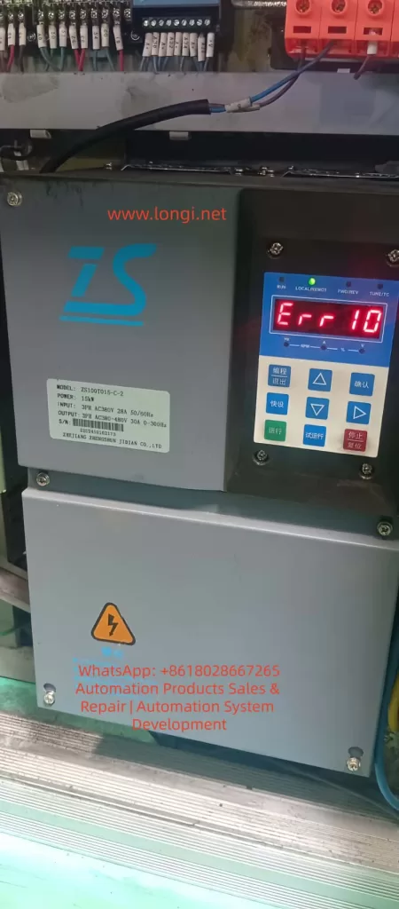
The Zhensun Servo ZS100 series is a dedicated control system designed specifically for hydraulic servo oil pump systems. It consists of the ZS100 series servo drive, ZM permanent magnet synchronous servo motor, and ZB braking unit. Covering a power range from 7.5kW to 75kW, it adopts Closed-loop Vector Control (VCC) with a maximum frequency of 300Hz, starting torque of 180% at 0Hz, speed regulation range of 1:1000, stability accuracy of ±0.02%, and an overload capacity of 150% rated output current for 100s or 180% rated output current for 5s. The system is widely used in hydraulic equipment such as injection molding machines, die-casting machines, and spinning machines, emphasizing high reliability, high stability, and cost-effectiveness. In practical field applications, the ERR10 fault (displayed as “Err 10” on the panel) is one of the most frequent alarms, directly affecting equipment operational safety. Based on the complete structure of the ZS100 series manual, this article provides a comprehensive operational guide covering fault definition, internal coding mechanisms, in-depth analysis of four causes, step-by-step diagnosis procedures, targeted solutions, parameter optimization for prevention, and typical case reviews, helping engineers quickly locate and thoroughly resolve the issue.
I. Nature of ERR10 Fault and Alarm Trigger Mechanism
The panel display for ERR10 corresponds to the fault name “Drive Overload”. In the drive’s internal fault address 8000H, its code is 000A, listed alongside ERR02~ERR07 (overcurrent/overvoltage series), ERR09 (undervoltage), and ERR11 (motor overload). The trigger conditions are strictly based on the drive’s hardware protection logic: when the output current continuously exceeds the rated value and surpasses the overload tolerance time, or when IGBT module temperature/bus voltage abnormalities cause a protection action, the system immediately locks the PWM output, the panel red light flashes, and “Err 10” is displayed. Unlike ERR11 (motor overload), ERR10 focuses on the drive unit’s own load-bearing capacity rather than the motor winding thermal protection.
1. Trigger Logic
Trigger conditions are strictly based on drive hardware protection logic:
- When output current continuously exceeds the rated value and exceeds overload tolerance time;
- Or when IGBT module temperature/bus voltage abnormalities cause protection actions;
- The system immediately locks PWM output, panel red light flashes, and displays “Err 10”.
Note: Unlike ERR11 (motor overload), ERR10 focuses on the drive unit’s load-bearing capacity, not motor winding thermal protection.
2. Trigger Paths
- Current Detection Circuit: Hall sensor or shunt resistor samples three-phase output current in real-time. Triggers after exceeding 150% rated value for 100s or 180% for 5s.
- Pressure Feedback Abnormality: Abnormal pressure sensor feedback (terminal A13) causes the control loop to output excessive setpoints, indirectly amplifying current.
- Hardware Abnormality: IGBT short-circuit leakage current directly increases bus current.
3. Reset Method
- Press the panel “Stop/Reset” button (red button);
- Or clear via DI digital input (D11~D15 programmed as reset signal).
- Warning: Root cause must be eliminated before reset, otherwise repeated triggering will cause permanent drive damage.
II. In-depth Analysis of Four Major Causes
Section 4.1 of the manual clearly lists the troubleshooting checklist for ERR10, totaling four items, each corresponding to high-frequency field scenarios. The following analysis combines system specifications, wiring, parameters, and hydraulic application characteristics.
Cause 1: Drive Undersizing
Core Basis: ZS100 series sizing core basis is the table in Section 1.2.
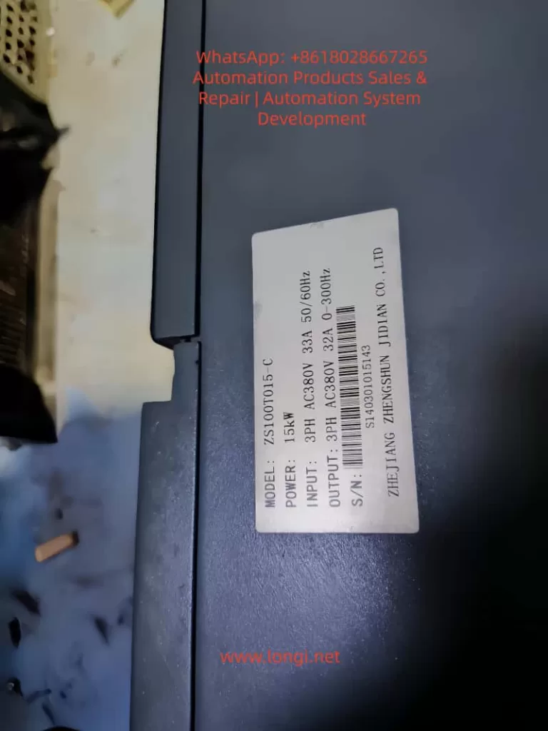
- Example: Take ZS100T015-C (15kW, rated output current 32A). If actual hydraulic pump power demand reaches 18kW (considering 1.2~1.5x safety margin), the drive capacity is insufficient.
- Risk: Hydraulic pump starting torque peaks can reach over 200%. If sizing only matches rated power, long-term operation will inevitably overload.
Peripheral Component Matching Key Points (Section 1.5):
- MCCB needs ≥63A, contactor ≥40A, input wire ≥6mm². If wires are too thin or contactor capacity is insufficient, contact resistance heating further amplifies overload.
- Braking Unit: 15kW model built-in braking resistor recommended ≥32Ω/100W. Without external braking unit or if resistance value is too large, deceleration energy cannot be released, indirectly raising bus voltage and current.
Quantitative Judgment: Measured output current (A01/A02 analog output) long-term ≥110% rated value indicates undersizing.
Cause 2: Excessive Load or Motor Locked Rotor
High-load scenarios specific to hydraulic systems:
- Relief valve not fully open, pump blockage, injection/clamping pressure set too high;
- Oil temperature too low causing viscosity increase, pipeline leakage causing excessive compensation current.
Locked Rotor Characteristics:
- When motor locks, three-phase current instantly reaches over 300%, triggering ERR10 within 5s.
- Criteria: Speed feedback (PG card SIN/COS signal) is 0 while set frequency >0Hz, or A13 pressure feedback suddenly rises to upper limit.
- Commissioning Risk: Section 3.2 of commissioning flow clearly states that if load tuning (P1.16=2) fails during motor trial run, overload is easily caused by locked rotor. ZS100 overload protection time is strict: must act after 150% for 100s, otherwise IGBT burn risk is extremely high.
Cause 3: Drive Hardware Failure
Fault Scope: Includes IGBT module aging, current sensor drift, main control board/drive board abnormalities, lightning protection board breakdown.
- Accompanying Fault: ERR18 (current detection fault) often accompanies ERR10.
- Hardware Failure Features: ERR10 reported even without load, or three-phase current severely unbalanced (>20%).
Board-level Check Points:
- Bus capacitor capacity attenuation (measured voltage fluctuation >10%);
- Cooling fan speed <2000rpm;
- IGBT module Vce saturation voltage drop abnormality.
- Environmental Impact: 15kW model weighs 6.5kg. When installation environment temperature exceeds 40℃ or vibration >5.9m/s², hardware life significantly shortens.
Cause 4: Pressure Sensor Failure
ZS100 is optimized for hydraulic servo pumps. Terminal A13 (pressure sensor feedback) connects to ±10V or 0~20mA signal (selected by J5 jumper).
Fault Mechanism: Sensor output abnormality (open circuit, short circuit, zero drift >0.5%) causes closed-loop vector control to misjudge insufficient pressure, automatically increasing torque setpoint and causing current surge.
Typical Manifestations:
- Panel shows ERR10 while A13 input voltage remains constant at 0V or 10V limit values.
- If 13V sensor power supply (+13V~GND) output deviation >±10%, it will also indirectly trigger.
- Requirement: Hydraulic system pressure fluctuates greatly (0~250bar), requiring high sensor pressure resistance and linearity.
III. Standardized Diagnostic Procedure (30-Minute Positioning Method)
Strictly follow the five-step method of “Power-off Inspection—Power-on Parameters—Load Isolation—Sensor Verification—Hardware Measurement” to avoid blind reset.
1. Safety Power-off Inspection (5 minutes)
Cut off main power R/S/T, wait for bus capacitor to discharge to <36V (confirm with multimeter DC range). Check:
- Main Circuit: Whether wires (U/V/W) are loose or insulation damaged;
- Grounding: Whether grounding terminal ⊕ is reliable (<0.1Ω);
- Braking Resistor: Whether (+、PB) connections are correct and resistance matches (15kW ≥32Ω);
- Sensor: Whether pressure sensor wires (A13-GND) have open or short circuits.
- Nameplate Check: ZS100T015-C-2 input 28A/output 30A, matches actual pump power?
2. Parameter Check and Self-Learning (10 minutes)
After power-on, enter P1 group (motor parameters):
- P1.01~P1.05: Confirm motor rated power, current, voltage, frequency, speed match ZM motor nameplate;
- P1.15: Motor overload coefficient default 1.0;
- P1.16: Execute static self-learning (=1) or dynamic self-learning (=2), must open relief valve before running. Learning failure directly correlates with ERR10.
- P0.02: =0 (panel control), confirm no external CAN setpoint interference.
- PD Communication: Check Appendix J (if using Modbus): baud rate consistent, address unique, timeout 0.0s (avoid ERR16 interference).
3. Load Isolation Test (5 minutes)
Disconnect motor from pump coupling (or close all valves), execute no-load trial run:
- Press “Run” key, observe output current (A01 set as current monitoring, J4 jumper voltage output).
- If ERR10 still reported: Exclude excessive load, pointing to hardware or sizing issues.
- If current normal: Reconnect pump, gradually increase pressure (from 10bar), monitor corresponding relationship between A13 pressure feedback and current.
4. Pressure Sensor Special Verification (5 minutes)
- Measure +13V~GND output: should be 13V±1.3V;
- Measure A13-GND voltage: 0V at no pressure, 10V at full pressure (or 20mA range);
- Calibration: Calibrate sensor with standard pressure source. If output deviation >2%, replace immediately (recommend 0~350bar 4~20mA type).
- Hardware: Confirm J5 jumper correctly selects voltage/current input mode.
5. Hardware Deep Measurement (5 minutes)
- Current Balance: Three-phase output current balance <5%;
- Bus Voltage: (+、-) stable at 540V±10%;
- Temperature: IGBT module temperature sensor (if any) <80℃;
- Fault Troubleshooting: If current sensor failure suspected, refer to ERR18 troubleshooting: replace drive board or main control board.
IV. Targeted Solutions and Field Operation Standards
1. For Undersizing
- Recalculation: Hydraulic pump theoretical power = pressure × flow × efficiency coefficient (usually 1.15~1.3).
- Hardware Upgrade: Upgrade to next level (e.g., ZS100T018-C 18kW). Simultaneously upgrade MCCB, wires, and filter per Section 1.5.
- Braking Unit: Install external braking unit ZB-70-B (mandatory for 37kW+).
2. For Excessive Load/Locked Rotor
- Mechanical Inspection: Open relief valve fully, clean pump filter; immediately stop if motor locks, check if pump shaft is stuck or oil solidified.
- Parameter Adjustment: Reduce pressure setpoint (AI1 terminal) or flow setpoint (AI2).
- PID Optimization: Optimize P3 group PID parameters (reduce proportional gain by 20%~30%, extend integral time).
3. For Hardware Failure
- Module Replacement: Replace corresponding module (IGBT module must match model);
- Maintenance: Clean heat sink, fan speed test >2800rpm;
- Return to Factory: Return entire unit or replace drive (free during warranty).
4. For Pressure Sensor Failure
- Replacement: Replace with same specification sensor, re-zero (pressure feedback zero calibration in P parameters);
- Anti-interference: Add shielded wire, keep away from strong current interference;
- Bus Check: For multi-unit systems, check CAN bus terminal resistance (J8 jumper).
Post-reset Monitoring: Must monitor for 30 minutes. Confirm current <105% rated value, pressure stable, no abnormal noise before putting into production.
V. Parameter Optimization and Preventive Maintenance System
Preventing ERR10 core lies in parameter closed-loop and regular maintenance:
- Regular Self-learning: P1.16 execute dynamic self-learning monthly;
- Real-time Monitoring: A01/A02 output monitoring current/pressure, connect to PLC upper limit alarm;
- Environment Control: Ambient temperature -10~40℃, humidity <95%RH, altitude <1000m;
- Tightening Check: Every 3 months check wiring tightening torque (main circuit 4~6N·m), clean air duct;
- Braking Monitoring: Braking resistor temperature monitoring <120℃, upgrade power if necessary;
- Function Enable: Ver 2.0 parameters (ZS200 compatible) add jitter suppression and pressure overshoot functions, can reduce overload risk.
VI. Typical Case Reviews (Injection Molding Machine Site)
Case 1: Undersizing
- Phenomenon: 15kW ZS100T015-C unit, frequent ERR10 during injection.
- Diagnosis: Actual pump power needed 17kW, undersizing.
- Solution: Upgraded to ZS100T018-C, current peak dropped to 85%, fault eliminated.
Case 2: Sensor Aging
- Phenomenon: Pressure sensor aged, A13 constantly 0V, causing torque setpoint to surge.
- Solution: Replaced sensor + zero calibration, system pressure fluctuation reduced from ±15bar to ±3bar.
Case 3: Mechanical Locked Rotor
- Phenomenon: Motor locked (filter clogged).
- Diagnosis: Normal operation after isolating pump.
- Solution: Cleaned filter, restored normal operation.
Case 4: Hardware Drift
- Phenomenon: Current sensor drift.
- Solution: Replaced drive board, ERR10 permanently disappeared.
Conclusion: From Passive Alarm to Active Protection
ERR10 is not an isolated fault, but the result of four-dimensional coupling among drive, motor, hydraulic load, and sensor. Mastering the complete ZS100 series architecture (Chapters 1~10 + Appendices), combined with the five-step diagnosis and four targeted solutions above, can compress fault downtime by over 90%.
Recommendation: Establish equipment files, execute quarterly “parameter backup—self-learning—load test—sensor calibration” maintenance, combined with PLC upper monitoring to achieve zero-fault operation. The key to hydraulic servo system efficiency and stability lies in “proper sizing, precise parameters, timely maintenance”. Strictly following this process will transform ERR10 from a “common fault” into a controllable risk that is “predictable and avoidable”.