
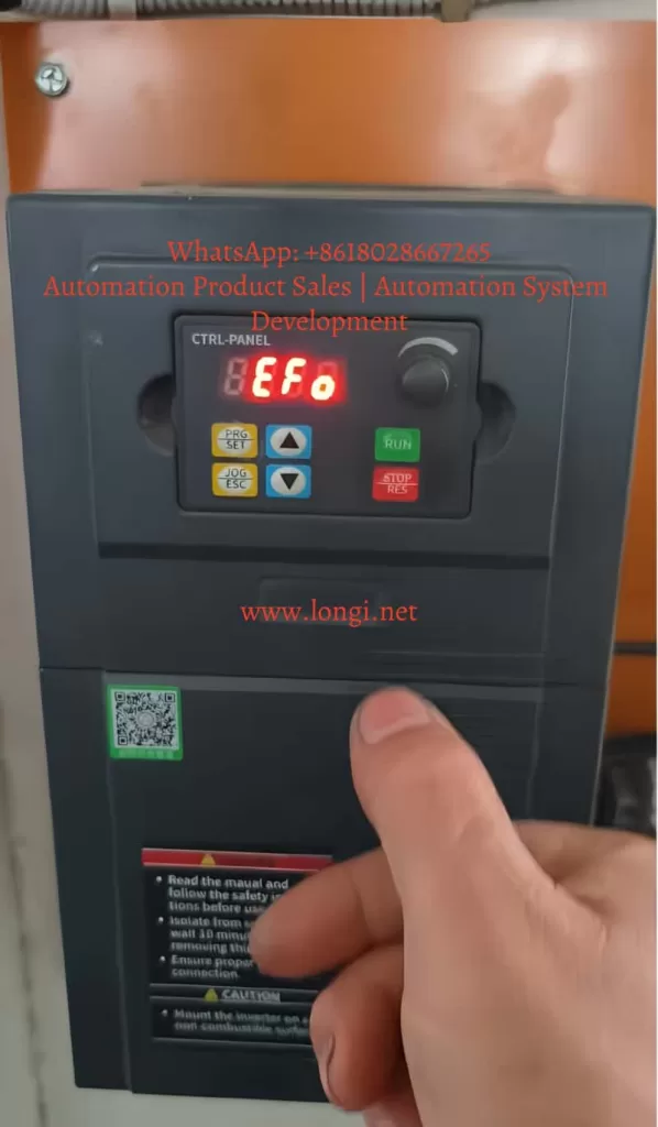
On Hailipu HIP320 series variable frequency drives, the EFO alarm is not a normal parameter warning. It is a power module fault. According to the HIP320 manual, EFO fault code 10 may be caused by output short circuit or grounding, instantaneous overcurrent, control board abnormality or severe interference, and damaged power components.
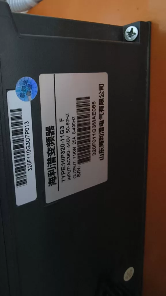
The unit shown in the photo is HIP320-11C3_F, with AC 380–440V input, 11kW output power, 25A rated output current, and 0–400Hz output frequency. When this type of drive reports EFO during operation, the fault should be diagnosed around the output circuit, motor cable, motor insulation, load condition, IGBT module, current detection circuit, driver board, and control board.
1. What EFO Means on the HIP320 Series
EFO means that the inverter has detected a serious abnormal condition in the power output section. It is more severe than a simple overload alarm.
A normal overload fault usually develops over time. For example, the motor is overloaded for a long period, the motor rated current is set incorrectly, or the load is too heavy. However, EFO often appears suddenly, especially during starting, acceleration, or when the inverter output is under stress.
Typical EFO symptoms include:
The inverter powers on normally, but trips as soon as RUN is pressed.
The inverter runs for several seconds or minutes, then trips with EFO.
The inverter runs normally without the motor, but trips when the motor is connected.
The inverter still reports EFO even when U, V, and W are disconnected.
The fault can be reset, but returns quickly after another start command.
These symptoms show that EFO must not be treated as a simple resettable alarm. Repeated reset and restart may damage the IGBT module, rectifier bridge, DC bus capacitors, or driver circuit.
2. Official Fault Causes
The HIP320 manual defines EFO as a power module fault. The listed causes are:
Output short circuit or grounding.
Instantaneous inverter overcurrent.
Control board abnormality or serious interference.
Damaged power device.
The corresponding countermeasures are to check motor wiring, refer to overcurrent countermeasures, and seek service when the control board or power devices are suspected.
In real field service, these causes are often connected. A motor cable insulation problem may cause output leakage. Output leakage may trigger instantaneous overcurrent. Repeated overcurrent may damage the IGBT module. A damaged IGBT may then cause EFO even with no motor connected.
3. First Determine When the Fault Appears
The most important step is to identify the fault condition.
3.1 EFO Appears Immediately After Power-On
If the drive displays EFO as soon as power is applied, before pressing RUN, the fault is usually inside the inverter. Possible causes include:
Shorted IGBT module.
Abnormal driver circuit.
Current detection circuit fault.
Control board misjudgment.
Abnormal switching power supply.
DC bus detection problem.
Moisture, dust, corrosion, or carbonized contamination on the PCB.
In this situation, do not connect the motor for testing. Disconnect power, wait for the DC bus capacitors to discharge, and inspect the main power circuit first.
3.2 EFO Appears Immediately After Pressing RUN
If the drive powers on normally but trips immediately after a run command, check the output side first:
U, V, W output short circuit.
Motor winding short circuit.
Motor cable insulation damage.
Output cable touching the cabinet or ground.
Loose terminal strands touching another terminal.
Water inside the motor terminal box.
A contactor, capacitor, or unsuitable device connected on the inverter output side.
Acceleration time too short.
Torque boost too high.
Incorrect V/F curve.
The manual clearly states that U, V, and W are inverter outputs for motor connection. Output wires must not be shorted or connected to the enclosure, and the PE terminal must be properly grounded.
3.3 EFO Appears After Running for Some Time
If the drive starts and runs for a short period before tripping, possible causes include:
Sudden mechanical load change.
Motor or load jamming.
Bearing damage.
Pump, fan, conveyor, reducer, or screw mechanism blockage.
Abnormal current rise at a certain frequency.
Motor insulation deteriorating after heating.
Poor inverter cooling.
IGBT thermal instability.
Driver board component thermal drift.
In this case, use the monitor parameters to observe running status. The HIP320 manual lists monitor parameters such as output frequency d-00, set frequency d-01, output voltage d-02, DC bus voltage d-03, output current d-04, input terminal status d-09, and temperature d-10. These parameters are useful for fault analysis.
3.4 EFO Only Appears When the Motor Is Connected
If the inverter runs normally with U, V, and W disconnected, but trips after connecting the motor, the external system is the first suspect:
Motor cable short circuit.
Motor insulation failure.
Motor winding short circuit.
Motor power mismatch.
Motor locked rotor.
Heavy starting torque.
Incorrect motor parameters.
Acceleration time too short.
Torque boost too high.
In this case, do not immediately judge the inverter as defective. Test the motor, cable, and mechanical load separately.
3.5 EFO Appears Even Without the Motor
If U, V, and W are disconnected and the inverter still reports EFO after a run command, the problem is probably inside the inverter:
IGBT leakage or short circuit.
Driver optocoupler or driver IC fault.
Upper/lower bridge driver abnormality.
Current sampling resistor, Hall sensor, or current transformer fault.
Module temperature detection abnormality.
Control board PWM output abnormality.
Control board power supply ripple.
Moisture or contamination on the control board.
This condition normally requires professional repair.
4. Check the Motor Cable, Grounding, and Insulation First
The most common external causes of EFO are output short circuit and grounding fault.
4.1 Power Off and Confirm DC Bus Discharge
For a 380V class inverter, the DC bus voltage can exceed 500VDC. After power-off, wait for discharge and confirm the DC voltage has dropped to a safe level before touching terminals.
4.2 Disconnect U, V, and W
Remove the motor wires from the inverter output terminals. Separate the inverter from the external motor circuit before measurement.
4.3 Measure Phase-to-Phase Resistance
Use a multimeter to measure:
U–V
V–W
U–W
The three readings should be balanced. If one pair is obviously much lower, the motor winding or cable may be shorted.
4.4 Measure Phase-to-Ground Insulation
Use a 500V megohmmeter to test:
U to PE
V to PE
W to PE
If insulation resistance is low or unstable, the inverter may trip with EFO under PWM output even if a normal multimeter does not show a direct short.
4.5 Inspect the Motor Terminal Box
Many EFO faults are caused by problems inside the motor terminal box:
Moisture.
Oil contamination.
Loose terminals.
Burned terminal block.
Carbon tracking.
Copper strands touching the enclosure.
Wrong star/delta connection.
Motor voltage mismatch.
In humid or dusty environments, leakage inside the terminal box is very common.
5. Check the Inverter Power Module
If the motor and cable are normal, or if the drive trips even without the motor, inspect the inverter main power circuit.
5.1 Check the Rectifier Section
With power disconnected and the DC bus discharged, use diode mode to check the rectifier bridge from R, S, T to DC+ and DC-. The readings should be consistent. A shorted rectifier usually causes input breaker tripping, but partial abnormalities can also destabilize the DC bus.
5.2 Check the IGBT Section
Measure:
U to DC+
U to DC-
V to DC+
V to DC-
W to DC+
W to DC-
U, V, W between phases
The readings should be generally balanced. If one phase is shorted, reads nearly zero, or conducts abnormally in both directions, the IGBT module is likely damaged.
5.3 Static Test May Not Find Every Fault
Some IGBT faults only appear under voltage, temperature, or dynamic switching. Static multimeter readings may look normal while the inverter still trips under operation. Possible hidden problems include:
High-voltage leakage.
Thermal leakage.
Insufficient gate drive voltage.
Distorted driver waveform.
Current detection error.
PWM control abnormality.
If the inverter trips with no motor connected, further bench testing is required.
6. Instantaneous Overcurrent and Parameter Problems
The HIP320 manual also connects EFO with instantaneous overcurrent. Overcurrent faults in the manual include hardware acceleration overcurrent, hardware deceleration overcurrent, hardware constant-speed overcurrent, software acceleration overcurrent, software deceleration overcurrent, and software constant-speed overcurrent. Listed causes include short acceleration time, short deceleration time, undersized inverter, improper V/F curve, improper torque boost, low supply voltage, sudden load change, and IGBT damage.
These conditions may also trigger EFO.
6.1 Acceleration Time Too Short
For high-inertia loads such as fans, centrifuges, mixers, conveyors, and pumps, short acceleration time can cause a large current surge.
Check and adjust:
F0.14 first acceleration time.
Increase acceleration time from 10s to 20s, 30s, or longer for heavy loads.
Observe d-04 output current.
Do not solve starting difficulty only by increasing torque boost.
6.2 Deceleration Time Too Short
Short deceleration time usually causes overvoltage, but in some mechanical systems it may also cause abnormal current. Increase F0.15 first deceleration time. If rapid stopping is required, check whether the braking resistor is correctly selected. The manual provides braking resistor recommendations for different power ratings.
6.3 Torque Boost Too High
F1.01 is the torque boost setting. Excessive torque boost increases low-frequency output voltage and motor magnetizing current. This may cause low-speed overcurrent, motor heating, vibration, noise, or EFO.
Corrective actions:
Reduce F1.01.
Check F1.02 torque boost cutoff frequency.
Use suitable V/F settings.
Check mechanical load before increasing boost.
6.4 Incorrect Motor Parameters
Check F9 group motor parameters:
Rated power.
Rated voltage.
Rated current.
Rated speed.
Rated frequency.
Stator resistance.
No-load current.
Incorrect motor data may distort protection behavior. Also confirm that the motor is suitable for inverter operation and matches the drive rating.
7. Check Input Power and DC Bus
Although EFO is a power module fault, unstable input power may indirectly cause it.
Check:
R–S voltage.
S–T voltage.
R–T voltage.
Input voltage balance.
Input contactor condition.
Breaker condition.
Loose terminals.
Cable crimp quality.
If one phase is loose or voltage drops under load, the inverter output current may become abnormal and trigger EFO.
The HIP320 monitor parameter d-03 shows DC bus voltage. If d-03 drops sharply during starting, inspect the input power supply before blaming the motor or inverter.
8. Control Board Abnormality and Interference
The manual also lists “control board abnormality or serious interference” as an EFO cause. This is common in industrial cabinets.
Possible interference sources include:
Large contactors.
Welding machines.
High-frequency heaters.
Servo drives.
Lightning surge.
Long control cables.
Analog signal wires routed together with power cables.
Poor grounding.
Several drives sharing a poor ground point.
Check whether control wires are separated from input power cables and motor cables. Analog signals should use shielded cable where necessary. The shield should be grounded properly.
Also check the control terminals COM, X1–X5, GND, AVI, ACI, AO, +10V, and relay output wiring. The HIP320 manual lists these terminal functions and confirms that COM is the digital signal common, while GND is the analog signal common.
Poor PE grounding can also cause random alarms, analog drift, communication instability, and control board malfunction.
9. Recommended Field Diagnosis Procedure
Use the following sequence.
First, record the fault condition:
Does EFO appear at power-on?
Does it appear after pressing RUN?
Does it happen only with the motor connected?
Does it happen at a certain frequency?
What is the output current before trip?
Has the motor, cable, load, parameter, or power supply been changed recently?
Second, disconnect U, V, and W and run the inverter without the motor.
If the inverter runs normally without the motor, check the motor, cable, insulation, grounding, mechanical load, and parameters.
If the inverter still reports EFO without the motor, inspect the inverter power module, driver board, current detection circuit, and control board.
Third, test the motor and cable with a megohmmeter.
Fourth, disconnect the mechanical load and test the motor alone.
Fifth, check key parameters:
F0.14 acceleration time.
F0.15 deceleration time.
F1.01 torque boost.
F1.03 carrier frequency.
F9.00–F9.04 motor parameters.
FA.05 current limit level.
FA.14 and FA.15 cycle-by-cycle current limit settings.
Sixth, inspect the inverter main circuit after power-off and discharge.
Seventh, if static measurements are normal but EFO remains, inspect the driver waveform, current sampling circuit, control board power supply, and PCB condition.
10. Can Factory Reset Solve EFO?
HIP320 parameter F0.17 is parameter initialization. The manual lists:
0: No operation.
1: Restore factory settings.
2: Fault clear.
Factory reset can help only if the fault is caused by incorrect parameters. It cannot repair a shorted motor cable, damaged IGBT, bad driver board, or contaminated control board.
Factory reset may be considered when:
The previous parameter settings are unknown.
The inverter hardware tests normal.
The inverter runs normally without load.
The fault is suspected to be caused by acceleration time, torque boost, V/F curve, command source, or motor parameter mismatch.
Do not rely on factory reset when:
EFO appears at power-on.
EFO appears with U, V, and W disconnected.
There is burning smell or visible damage.
IGBT measurement is abnormal.
Motor insulation is poor.
Before resetting, record important parameters such as motor data, command source, frequency source, digital input functions, relay output function, and process settings.
11. When Field Repair Is Possible
Field correction is usually possible when:
The inverter runs normally without the motor.
The motor cable insulation is poor.
The motor terminal box is wet or contaminated.
The mechanical load is jammed.
Acceleration time is too short.
Input voltage is unbalanced.
Grounding is poor.
Control wiring interference is obvious.
These are external system faults.
12. When Professional Repair Is Required
Send the inverter for repair when:
EFO appears with no motor connected.
EFO appears immediately after power-on.
IGBT static measurement is abnormal.
U, V, W output terminals show short circuit.
There is internal burning or explosion damage.
The driver power supply is abnormal.
The control board is corroded, wet, or burned.
Different motors produce the same EFO fault.
In professional repair, the technician should check not only the IGBT module but also the driver circuit, gate resistors, driver optocouplers, gate protection components, current detection circuit, DC bus capacitors, rectifier bridge, control board power supply, cooling fan, and heatsink condition.
13. Preventing EFO from Returning
To reduce future EFO faults:
Keep the motor cable as short as possible. The manual recommends that the motor cable should preferably not exceed 50 meters to reduce leakage current.
Do not install a contactor on the inverter output side unless the system is correctly interlocked and switching occurs only when the inverter has stopped output.
Check motor insulation regularly, especially in humid, dusty, oily, or outdoor environments.
Set acceleration and deceleration times according to actual load inertia.
Do not use excessive torque boost.
Separate control wiring from power wiring.
Use shielded cable for analog signals when required.
Ensure reliable PE grounding.
Clean the cooling fan, air duct, and heatsink regularly.
Conclusion
The EFO fault on a Hailipu HIP320 VFD is a power module protection alarm. It may be caused by output short circuit, grounding fault, motor insulation failure, cable damage, load jamming, instantaneous overcurrent, severe interference, driver circuit failure, current detection error, or damaged IGBT power devices.
The correct diagnostic principle is:
Check external wiring before internal hardware. Isolate the motor before testing the inverter. Measure before resetting. Find the cause before replacing components.
If the inverter runs normally with U, V, and W disconnected, focus on the motor, cable, grounding, load, and parameters. If the inverter still reports EFO without the motor, the fault is most likely inside the inverter and should be repaired professionally. Repeated reset and forced restarting are not recommended, because they may turn a minor output fault into serious power module damage.