
1. Introduction: Why Er.740 Is Frequent and Often Misdiagnosed
In real-world applications of the Inovance SV630P servo system, Er.740 is a typical composite fault involving both signal integrity and system state. It is not a simple hardware failure indication, but rather the result of multiple interacting factors, including encoder signal integrity, power-up conditions, mechanical behavior, and electromagnetic environment.
A common mistake in the field is to assume “encoder failure” and immediately replace the motor or encoder. However, statistical experience shows:
- Over 60% of Er.740 cases are caused by wiring or interference
- Around 25% are due to improper power-up conditions or motion state
- Actual hardware failure accounts for less than 15%
Therefore, this fault must be analyzed using a system-level engineering approach rather than component replacement.
2. Definition and Nature of Er.740
According to the SV630P manual:
Er.740: Encoder interference
Essence: Abnormal encoder feedback leading to excessive electrical angle deviation
From a control perspective, the servo drive relies on encoder feedback to obtain:
- Position
- Speed
- Electrical angle
If the encoder signal becomes abnormal:
- Field-Oriented Control (FOC) fails
- Current loop and speed loop decouple incorrectly
- The drive triggers protection and stops immediately
Therefore, Er.740 is fundamentally a closed-loop control failure protection mechanism.
3. Key Observations from the Provided Field Data
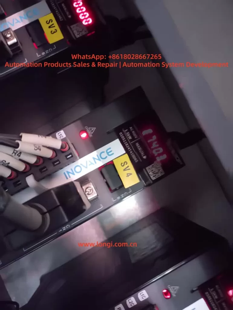
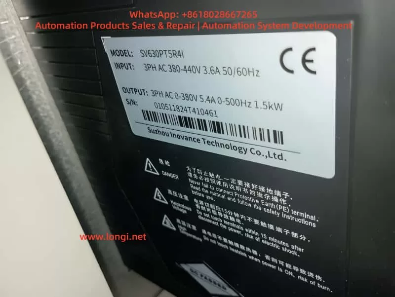
Based on the images and notes provided, several important points can be identified:
1) Equipment status
- Inovance SV630P servo drives
- LED indicators active with alarm condition
- Multi-axis system (SV3 / SV4 labeling)
2) Encoder type (inferred)
Based on documentation:
- Absolute encoder (with battery backup)
- Supports standby mode operation
3) Critical note from documentation
Key instruction:
- Encoder communication starts about 5 seconds after power-on
- Motor speed must be ≤10 rpm during startup transition
- Otherwise, Er.740 may occur
This implies:
Er.740 is not only a hardware issue, but also strongly related to power-up motion conditions.
4. Six Typical Causes of Er.740
1. Incorrect encoder wiring (most common)
Symptoms:
- Alarm immediately after power-on
- Continuous or intermittent
Typical issues:
- CN2 connector miswired
- Signal lines swapped or incorrect
- Power and signal lines mixed
2. Loose encoder cable or poor contact
Characteristics:
- Fault occurs after some runtime
- More frequent under vibration
Mechanism:
- Intermittent signal → data corruption → drive fault
3. Electromagnetic interference (EMI)
Typical scenarios:
- Encoder cable routed with power cable
- Improper shielding or grounding
- Nearby high-frequency equipment (VFDs, welders)
Mechanism:
- Encoder signals are low-voltage differential signals
- Highly susceptible to noise
4. Motor movement during power-on (critical factor)
Often overlooked:
If any of the following occurs:
- Load causes motor rotation at power-on
- High inertia system is not locked
- External force drives the motor
Then:
- Encoder is not yet initialized
- Angle data becomes unstable
- Er.740 is triggered
5. Encoder battery issues (absolute encoder systems)
Symptoms:
- Intermittent alarms
- More frequent after power cycling
Causes:
- Low battery voltage
- Multi-turn data loss
- Initialization failure
6. Encoder or interface hardware failure
Less common but possible:
- Encoder internal damage
- CN2 interface failure
- Sensor element malfunction
5. Recommended Troubleshooting Procedure
Step 1: Basic inspection (highest priority)
- Check encoder connectors for looseness
- Verify shielding and grounding
- Inspect cable condition
This step resolves a large percentage of cases.
Step 2: Verify wiring compliance
Ensure:
- Power and signal cables are separated (≥30 cm)
- Shield is properly grounded
- No shared conduit
Step 3: Check power-on behavior (critical)
Verify:
- Motor is stationary during power-on
- No external force is acting
- No inertia-driven movement
Solutions:
- Add mechanical brake
- Lock shaft before power-on
- Adjust control logic
Step 4: Check encoder battery
- Measure battery voltage (typically 3.6V)
- Replace if below threshold
- Reinitialize after replacement
Step 5: Interference verification
Methods:
- Temporarily separate cables
- Add ferrite cores or filters
- Observe if fault disappears
Step 6: Replacement method (final step)
Replace components in sequence:
- Encoder cable
- Motor
- Drive
Identify root cause step by step
6. Engineering Design Recommendations
1. Cable design
- Use twisted-pair shielded encoder cables
- Independent routing paths
- Reliable grounding
2. Power-on strategy
Recommended logic:
- Power-on → delay → enable servo
- Prevent motion during startup
3. Mechanical design
- Install brake for high inertia systems
- Prevent free rotation
4. EMI control
- Add EMC filters
- Use ferrite cores
- Optimize grounding system
5. Preventive maintenance
- Check connectors regularly
- Replace battery every 2–3 years
- Ensure tight wiring
7. Typical Field Cases
Case 1: Alarm at power-on
Cause:
- Conveyor inertia causing rotation
Solution:
- Add braking mechanism
Case 2: Alarm after 1 hour
Cause:
- Loose encoder connector
Solution:
- Re-terminate connection
Case 3: Random alarms
Cause:
- Encoder and power cables routed together
Solution:
- Separate routing
Case 4: Frequent alarms after shutdown
Cause:
- Low encoder battery
Solution:
- Replace battery
8. Conclusion
Er.740 is not simply an “encoder failure” but a system-level fault caused by:
- Encoder signal integrity
- Power-on conditions
- Electromagnetic environment
The correct approach is:
- First eliminate wiring and EMI issues (majority of cases)
- Strictly control startup conditions (critical factor)
- Only consider hardware replacement as the final step
With proper wiring, startup control, and EMI design, Er.740 can be effectively prevented in long-term operation.