
Introduction
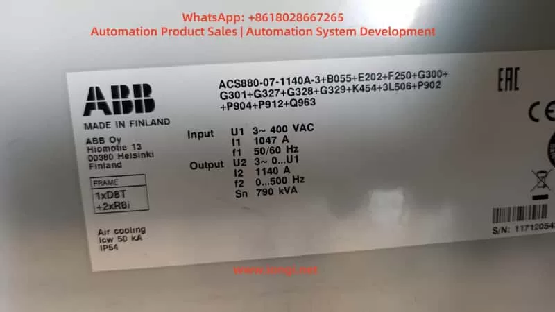
The ABB ACS880 series is a benchmark product in the industrial drive field. The ACS880-07 cabinet model is specifically designed for high-power multi-module applications. A typical configuration, as seen in user cases, is the ACS880-07-1140A-3 (rated output 790 kVA, FRAME 1xD8T + 2xR8i). This model adopts air cooling (IP54), three-phase 400 V input, and 1140 A output current, widely used in heavy-duty machinery, fans/pumps, and process production lines.
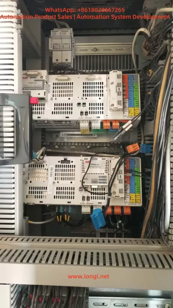
Its core architecture includes an independent Line Side Unit (LSU, typically a diode-type D8T module) and an inverter unit (2×R8i power modules), managed by two BCU control units (BCU-02/12/22 series):
- One BCU is responsible for LSU power supply logic;
- The other is responsible for inverter DTC control and motor output.
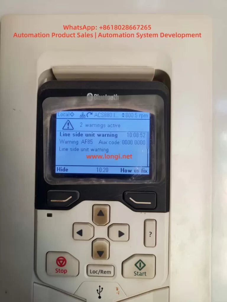
In actual operation, the phenomenon where the panel displays “AF85 Line side unit warning” (Aux code 0000 0000) accompanied by “2 warnings active”, followed by a total system failure (“not working at all”) and only one BCU being visible on the panel after replacing the battery for “CPU battery dead” (with RO3 relay output only showing on one side), is a typical composite fault chain in the dual-BCU configuration of the ACS880-07.
This article provides a systematic analysis of the hardware architecture, firmware mechanisms, warning decoding, battery replacement pitfalls, communication recovery, and prevention strategies. It combines official ABB firmware manuals (ACS880 Primary Control Program Firmware Manual, IGBT Supply Control Program Firmware Manual, BCU-x2 Hardware Manual) with practical cases to offer actionable diagnosis and repair paths.
⚠️ Safety Declaration: All operations must strictly comply with the ABB Safety Manual (3AUA0000102301): Cut off main power, close the Q9 grounding switch, and wait for the DC link to discharge to a safe voltage.
1. ACS880-07 Cabinet Architecture: Multi-Module and Dual BCU Control Logic
The ACS880-07 cabinet adopts a modular stacking design:
- Left side: Power Supply Unit (D8T frame), responsible for AC-DC rectification;
- Right side: Parallel R8i inverter modules, providing DTC vector control.
Power parts are connected via busbars, while the control layer relies on BCU (Basic Control Unit) for distributed management.
1.1 BCU Control Unit and Communication Architecture
Unlike the single-unit ZCU, the BCU supports up to 12 channels of optical fiber (BCU-22), dedicated to parallel modules or multi-unit cabinets. Typical configuration:
| BCU Location | Slot Position | Managed Object | Core Functions |
|---|---|---|---|
| BCU1 | SLOT 2/3 Upper | LSU (D8T) | Handles charging, MCB closing, DC voltage monitoring |
| BCU2 | SLOT 3 Lower | 2×R8i Inverters | Handles motor current sampling, DTC algorithm, RO1/RO2/RO3 relay outputs |
- Communication Link: Uses DDCS (Distributed Drive Control System) optical fiber link (orange/blue POF fiber, max 35 m), supplemented by D2D (Drive-to-Drive) link for status word synchronization.
- Key Parameter: Parameter 95.20 HW options word 1 determines the INU-LSU communication mode (Bit 11 activates diode supply control, Bit 15 activates IGBT type).
- Panel Display: The keypad defaults to showing “Main BCU” parameters (visible in Group 96 System info). Switching requires the Diagnostics menu or Drive Composer to view both BCUs simultaneously.
1.2 Hardware Key Points
- Real-Time Clock Battery (CR2032): Powers the BCU’s RTC and parameter buffer. After power loss, parameters are stored on the SDHC memory card (slot X205).
- External 24 V Power (XPOW): The BCU must be externally powered (Parameter 95.04 set to External 24V). Redundant input is supported to prevent AFEC warnings.
- Cooling and Protection: IP54 air cooling, 50 kA short-circuit withstand. Over-temperature triggers AE14/AE16 aux codes directly.
Architecture Conclusion: The AF85 warning inevitably originates from the LSU side, while the “one BCU visible, one BCU lost” phenomenon after battery replacement is a typical manifestation of DDCS link or memory synchronization failure.
2. ACS880 Firmware Warning Mechanism and In-depth Analysis of AF85
ACS880 uses a Primary Control Program (main program) and a dedicated Supply Control Program (power supply program). Warnings are divided into:
- Warning (AFxx): Operation can continue;
- Fault (Fxxx): Immediate shutdown.
2.1 AF85 Exclusive Mechanism
AF85 is exclusive to “Line side unit warning,” indicating that the LSU (or parallel converter) has generated a warning, which is forwarded to the main BCU panel via DDCS.
- Generation Principle: The LSU control board (independent firmware) detects an anomaly (e.g., AE01 overcurrent) → generates an original warning → The main BCU receives it and maps it to AF85.
- Aux Code: This is the original code from the LSU (format XXXX YYYY). In the user case, Aux Code 0000 0000 indicates a “generic unspecified mapping,” requiring a check of the LSU event log for confirmation.
2.2 Official Aux Code Mapping Table (Common Items)
Excerpted from the IGBT/Diode Supply Firmware Manual and Primary FW Manual page 539:
| Aux Code | Fault Name | Troubleshooting Direction |
|---|---|---|
| AE01 | Overcurrent | Input fuses, cables, harmonics |
| AE02 | Earth Leakage | Cable insulation (Check Parameter 31.120) |
| AE04 | IGBT Overload | Cooling fan blockage, ambient temp >40°C |
| AE09 | DC Link Overvoltage | Input voltage fluctuation, Parameter 195.01 setting |
| AE0A | DC Undervoltage | Phase loss, MCB not closed |
| AE14 | Over-temperature | Parameter 105.111 Line converter temperature |
| AE73 | Fan Fault | Parameter 105.04 Fan on-time counter limit exceeded |
| AE85 | Excessive Charging Count | Parameter 94.10 LSU max charging time (default >2 times within 15s) |
Field Tip: The “How to fix” button on the panel points directly to the Event Logger (Group 04). “2 warnings active” indicates a persistent issue on the LSU side. AF85 is only a Warning; the drive can still run at 800 rpm, but if unaddressed, it will escalate to 3E08 LSU charging fault.
3. Common Root Causes of AF85 and On-site Diagnosis Process
90% of AF85 issues stem from LSU hardware/environmental problems:
- Power Quality: Three-phase 400 V fluctuation > ±10%, harmonic THD > 5% (Check Parameter 01.102 Line current distortion) — Install input reactors.
- Cooling System: IP54 filter clogged, cabinet temperature > 45°C (Parameter 05.111 temp percentage > 90%) — Check door intake/top exhaust filters.
- Wiring and Protection: Loose input cables, poor grounding, blown fuses (AE02 aux code) — Re-torque (M12 bolts at 18 Nm).
- Charging Circuit: MCB closing delay, aging pre-charge resistor (94.10 timeout) — Set Parameter 94.11 LSU stop delay to 600 s.
- Parallel Imbalance: Current difference between 2×R8i modules > 5% (AE02) — Check fiber optic connection consistency.
Diagnosis Steps (No Tools Required)
- Panel:
Diagnostics→Event log, record the AF85 timestamp (e.g., 10:08:52). - Parameters:
- 06.36 LSU Status Word (Bit 7 = Warning);
- 06.116 LSU drive status word 1.
- 95.01 Supply voltage to confirm 400 V.
- Physical Check: Fans rotating, no loose cables, DC link voltage (01.01) stable.
If the aux code remains 0000 0000, upgrade to the Drive Composer PC tool (USB connected to panel port) to read the LSU-specific event log.
4. Function of BCU RTC Battery and Standard Replacement Procedure
The built-in CR2032 battery (3 V lithium) in the BCU is responsible for:
- RTC real-time clock (event log timestamps);
- Temporary storage of parameter buffer (no loss if power off < 5 min);
- Backing up parameters to the SDHC card (slot X205).
When the battery is dead (BATT LED off), the panel still displays, but event log timestamps become chaotic, and parameter backup fails. This is the typical symptom of “battery dead of CPU.”
⚠️ Standard Replacement Procedure (from BCU-02/12/22 Hardware Manual)
- Shutdown: Stop the machine, cut off main power, close Q9, wait for DC discharge (>5 min, multimeter <50 V).
- Locate Hardware: Open the cabinet door, locate the BCU (SLOT marking).
- Cut Auxiliary Power: Unplug XPOW external 24 V (to prevent residual voltage).
- Replace Battery: Unscrew the battery compartment fixing screw (1 piece), remove the old battery (note polarity: + facing up).
- Insert New Battery: Insert new CR2032 (ABB original or equivalent, capacity ≥220 mAh).
- Reassemble: Screw the cover back on, restore XPOW.
- Critical Step: If replacing the BCU unit itself, the SDHC memory card must be transplanted (to maintain parameters)!
- Power Up:
- Panel → 96.51 Clear fault logger;
- Drive Composer → Backup/Restore all parameters.
❌ Common Errors (Main causes of “bricking”)
- Hot-swapping: Causes BCU lock-up;
- Not transplanting memory card: Parameters lost, dual BCU desynchronization;
- Not saving parameters: Group 96 parameters not cleared or backed up.
5. Root Cause Analysis of “One BCU Visible, One BCU Lost” After Battery Replacement
The phenomenon of the whole machine not working and only one BCU showing RO3 on the panel after battery replacement is essentially dual-BCU communication desynchronization:
- RTC/Buffer Cleared: Dead battery causes RTC/buffer to reset to zero. The second BCU (usually the inverter side) fails to complete DDCS synchronization upon power-up.
- Fiber Link Fault: Loose/dirty fiber optics (reports AE56 INU-LSU comm loss), bent connectors.
- Memory Card Recognition Failure: AE75 SD card error, Parameter 95.14 Connected modules mismatch.
- 24 V Power Fluctuation: AFEC External power signal missing, Parameter 95.04 not set to Redundant.
- RO3 Visible on One Side Only: Since RO1/RO2/RO3 (XRO1-3) are bound to the Main BCU, the auxiliary BCU not being online makes the parameter group invisible.
Correlation: The customer reported “PLC signals not given” because with the BCU not fully online, the Profibus/FPBA-01 adapter cannot exchange control words.
6. Advanced Diagnosis and Precise Recovery Operations
Step 1: Quick Panel Check
- Switch BCU View:
Diagnostics→Control unit selection. - Check Faulty Modules: 04.25 Faulted modules (BCU specific).
- Export Log: Use “How to fix” to export timestamps.
Step 2: Drive Composer Deep Recovery (Highly Recommended)
- Connect: Connect via USB to the panel or Ethernet (XETH).
- Scan: Scan both BCUs simultaneously. Check fiber status (Group 60 DDCS) and Parameter 95.20 bit settings.
- Compare: Compare parameters of dual BCUs (especially Group 95 hardware configuration).
- Force Synchronization:
- Backup current parameters → Restore to the lost BCU → Restart (power off for 5 min).
- View the complete aux code in the event log (instead of 0000 0000).
Step 3: Hardware Verification
- Fiber Optics: Clean connectors (anhydrous alcohol), confirm TX/RX alignment, no bending (radius >30 mm).
- Power Supply: Measure XPOW 24 V (dual redundancy).
- Relays: Check continuity of RO3 relay (XRO3 terminal).
- Last Resort: If still lost, set Parameter 95.16 Router mode to On (BCU specific), or replace the lost BCU (must transplant memory card).
Step 4: PLC Side Linkage
- Confirm FPBA-01 adapter parameters (Group 50 FBA A), cyclic data 10/11 (Control Word/Status Word).
- Crucial: The PLC must only send the start signal after the drive is fully online.
7. Real Case Study: 1140A Dual-BCU System Recovery
- Device Info: Serial No. 11712054 (Made in Finland), ACS880-07-1140A-3.
- Fault: Initial AF85 (Aux code 0000 0000, suspected AE73 fan or AE09 voltage). System “bricked” after battery replacement; panel showed only one BCU with RO3.
- On-site Operation:
- Drive Composer Connection: Found inverter BCU fiber link timeout (AE56).
- Action: Cleaned fiber connectors + Parameter Restore (full overwrite to lost BCU).
- Result: Synchronization successful. Cleared event log.
- Reset: Set 94.01 LSU control = On.
- Outcome: Test run stable at 800 rpm, AF85 disappeared, PLC signals normal.
- Time Spent: 2 hours (saved tens of thousands of dollars by avoiding module replacement).
8. Best Practices for Preventive Maintenance
To avoid such composite faults, implement the following strategies:
- Annual Battery Check: Replace when the BATT LED is lit (lifespan 3-5 years). Do not wait for “CPU battery dead” alarm.
- Parameter Backup System: Perform a full backup to PC using Drive Composer monthly and export event logs (.txt/.csv).
- Fiber Maintenance: Clean fiber tips every six months. Check bending radius >30 mm to prevent dust accumulation.
- Environmental Monitoring: Install temperature/humidity sensors inside the cabinet, linked to AE14 over-temperature warning.
- Firmware Upgrade: Confirm the latest Primary/Supply programs (e.g., version 7.24) to fix old communication bugs.
- Redundancy Configuration:
- Set 95.04 to Redundant 24V;
- Optimize 94.10 charging time based on grid quality.
- Training: Operators must master the use of the “How to fix” button and event log export.
9. Conclusion
AF85 is not an isolated warning but a window into anomalies on the LSU side. Battery replacement, though seemingly simple, can easily trigger a system-level crash due to the communication dependency of the dual-BCU architecture.
Mastering DDCS fiber principles, the meaning of Group 95/96 parameters, and the forced synchronization function of the Drive Composer tool enables minute-level positioning and recovery. The power of the ABB ACS880-07 lies in its modularity and diagnostic depth, but this relies on standardized maintenance and documented operations.
Recommendation: All users should download the corresponding manuals and establish an event log archive. For complex cases, contact professional technical support first. Through systematic troubleshooting, you can not only solve current faults but also significantly improve equipment MTBF and ensure production line continuity.