
Introduction
In industrial automation fields such as injection molding machines, CNC machine tools, and packaging machinery, the HILECTRO HI300/HI360 series drives have become core power solutions for numerous equipment manufacturers due to their high reliability, precise vector control performance, and comprehensive protection functions. However, even industry-leading products are not immune to faults—among which, the ER053 “software undervoltage” fault is one of the most frequently reported issues by users. This fault can cause the drive to suddenly shut down and the motor to stop running, leading to production interruptions and raw material waste in mild cases, and motor or load machinery damage in severe cases.
This article provides a systematic analysis of the ER053 fault from six dimensions: fault definition, cause analysis, troubleshooting steps, solutions, case verification, and preventive maintenance. It aims to assist maintenance personnel in quickly locating problems, efficiently resolving faults, and offering long-term prevention strategies to ensure stable equipment operation.
I. Definition and Typical Phenomena of the ER053 Fault
1.1 Fault Code Meaning
The ER053 fault is a software undervoltage protection fault in the HILECTRO HI300/HI360 series drives, classified as a power-related fault. According to the manufacturer’s technical documentation, its triggering logic is as follows:
The drive’s internal CPU collects the input power supply voltage through voltage sensors. When the effective value of the line voltage is detected to be below 85% of the rated voltage (e.g., below 323V in a 380V system) and the duration exceeds the software-set delay threshold (typically 50-100ms), the software algorithm determines it as an “undervoltage” condition, triggering the ER053 fault and shutting down the drive.
Unlike hardware undervoltage protection (e.g., voltage relays directly cutting off the power supply), software undervoltage protection is more flexible—it filters out instantaneous voltage fluctuations (e.g., drops within 10ms) through algorithms to avoid false shutdowns. However, it may also lead to faults due to algorithm misjudgments or improper parameter settings.
1.2 Typical Fault Phenomena
The ER053 fault exhibits distinct “power-related” characteristics, which maintenance personnel can quickly identify through the following phenomena:
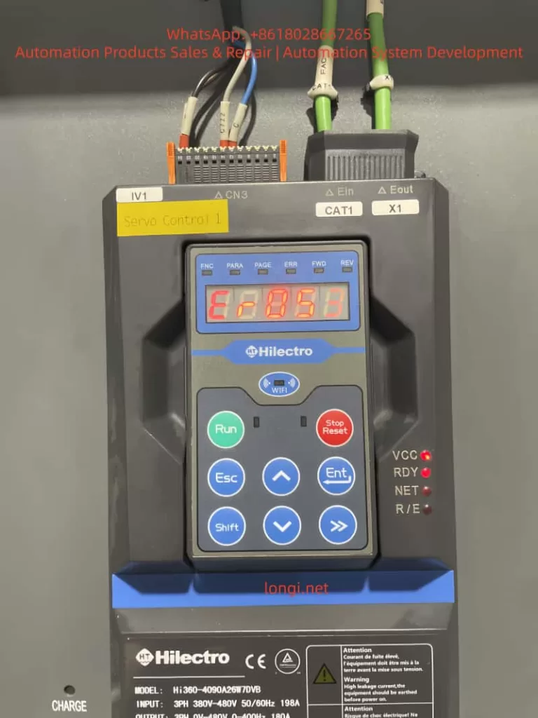
- Display Panel: The operation panel displays the “ER053” fault code with a red backlight, and some models may emit a “beep” alarm sound.
- Indicator Lights: The “RDY” (ready) light flashes or goes out, the “VCC” (power supply) light remains on, but the “NET” (network) light may flash.
- Equipment Status: The motor suddenly stops running, and the load machinery (e.g., injection molding machine screw, machine tool worktable) stalls or remains stationary.
- Accompanying Phenomena: The workshop lights may briefly dim, or nearby large equipment (e.g., air compressors, electric welders) may start up when the fault occurs.
II. In-depth Cause Analysis of the ER053 Fault
The core of the ER053 fault is “insufficient input power supply voltage,” but its causes involve four dimensions: the power supply side, the wiring side, the load side, and the drive’s internal circuitry, which need to be dissected one by one.
2.1 Power Supply Side: Grid Fluctuations or Instantaneous Power Outages
The grid is the power source for the drive, and its stability directly affects drive operation. Common issues include:
- Instantaneous Power Outages: When large equipment (e.g., 100kW air compressors, cranes) starts up, the grid current surges, causing the voltage to drop instantaneously (potentially below 50% of the rated voltage) for 5-100ms. For example, when an air compressor near an injection molding machine plant started up, the drive’s input voltage dropped from 380V to 280V for 60ms, triggering the ER053 fault.
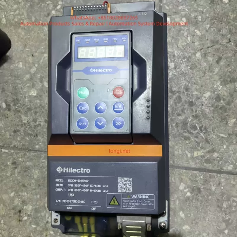
- Long-term Low Voltage: In remote areas or old grids, the voltage may remain below the drive’s minimum input requirement (380V ± 10% for the HI360 series) for extended periods. For instance, the grid voltage at a machine tool plant consistently remained at 350V, causing the drive to frequently report errors due to “borderline undervoltage.”
- Phase Loss or Phase Sequence Errors: Although phase loss usually triggers the ER001 fault, if it causes voltage imbalance in the remaining two phases, the software may misjudge it as an undervoltage condition (requiring judgment based on other fault codes).
2.2 Wiring Side: Loose Connections or Cable Defects
The contact resistance or cable losses in the input wiring can cause the “actual input voltage” to be lower than the “power supply end voltage,” making it a common cause of the ER053 fault:
- Loose Connections: The screws on the drive’s input terminals (L1/L2/L3) are not tightened properly, or the copper lugs are oxidized (blackened), increasing contact resistance. For example, a user’s L1 terminal screw torque was only 8N·m (standard: 15-20N·m), resulting in a 50V voltage drop at 100A current and reducing the actual input voltage from 380V to 330V.
- Cable Damage: The cable’s insulation layer is damaged due to prolonged bending or friction, or the copper core is oxidized (increasing resistance). For instance, after 5 years of use, the copper core resistance of a device’s cable increased from 0.1Ω to 0.5Ω, causing a 75V voltage drop at 150A current.
- Poor Grounding: Excessive PE grounding resistance (>4Ω) causes the voltage detection reference point to shift. For example, a user connected the grounding wire to a water pipe, resulting in a 10Ω grounding resistance and a 20V detection voltage error.
2.3 Load Side: Load Mutations or Overloads
Sudden changes in the load can cause the motor current to surge, pulling down the power supply voltage and triggering an undervoltage condition:
- Load Jamming: The injection molding machine screw gets jammed by cold material, or the machine tool’s ball screw bearing is damaged, causing a sudden increase in load torque. To overcome the load, the motor current surges (potentially reaching 2-3 times the rated current), pulling down the power supply voltage. For example, when an injection molding machine screw jammed, the current increased from 120A to 250A (rated 180A), and the voltage dropped from 380V to 310V.
- Overload Operation: Operating continuously beyond the motor’s rated load (e.g., setting the injection pressure of an injection molding machine higher than specified) causes the current to remain excessively high, lowering the voltage. A user increased the injection pressure from 100bar to 150bar to improve production output, causing the motor current to consistently exceed the rated value and the drive to frequently report the ER053 fault.
2.4 Drive’s Internal Circuitry: Detection Circuit or Software Issues
If the power supply, wiring, and load are all normal, internal drive faults must be considered:
- Voltage Sensor Damage: The Hall voltage sensor (detecting input voltage) may output a low voltage due to overheating or aging. For example, a drive’s sensor consistently output 1.2V (normal: 2.5V), causing it to report the ER053 fault even with normal input voltage.
- Sampling Circuit Faults: Increased resistance in sampling resistors (e.g., 10kΩ) or capacitor leakage can cause the sampling voltage to be low. For instance, a drive’s sampling resistor increased to 15kΩ, reducing the sampling voltage from 2V to 1.5V and causing the software to misjudge it as an undervoltage condition.
- Software Algorithm Misjudgments: Early software versions (e.g., HI360 V1.0) may have bugs in the voltage fluctuation filtering logic, causing false ER053 reports when voltage fluctuations exceed ±10%. Upgrading to V1.1 resolved the issue.
III. Systematic Troubleshooting Steps for the ER053 Fault
Troubleshooting the ER053 fault should follow the principle of “from the outside in, from simple to complex” to avoid盲目 (blindly) disassembling the drive. The following is a standardized process:
3.1 Step 1: Collect Fault Information (Critical!)
- Inquire from Operators: Gather information on the equipment’s state when the fault occurred (starting/running/stopping), load conditions (jamming/overload), surrounding environment (equipment starting/lightning), and previous operations (parameter changes/cable replacements).
- Observe Phenomena: Record the fault code (whether accompanied by other codes), indicator light states (RDY/VCC lights), motor sounds (abnormal noises), and load states (e.g., screw jamming).
- Check Historical Records: The HI360 series supports storing the last 10 faults. View the fault time and voltage values using the “PARA-97” parameter to determine if it is a recurring fault.
3.2 Step 2: Check the Input Power Supply (Basic Troubleshooting)
- Tools: Multimeter (Fluke 15B+, AC voltage range), oscilloscope (bandwidth ≥1MHz, sampling frequency ≥10MS/s), voltage tester.
- Operation Steps:
- Cut off the drive’s power supply and confirm no voltage at the input terminals using a voltage tester.
- Open the wiring cover and locate the input terminals (L1/L2/L3/N/PE).
- Measure the line voltage: L1-L2/L2-L3/L3-L1, which should normally be within 380-480V (HI360 range) with a deviation ≤ ±5%.
- Measure the neutral-to-ground voltage: N-PE, which should normally be <2V (good grounding).
- Capture instantaneous voltage drops using an oscilloscope (e.g., below 320V and lasting >50ms).
- Check the power switch/fuse for burn marks or looseness.
- Judgment Criteria: Voltage below 380V or instantaneous drops → power supply side issue; normal voltage → proceed to the next step.
3.3 Step 3: Check Wiring and Cables (Frequent Fault Points)
- Tools: Screwdriver (torque wrench), alcohol (to clean oxidation), multimeter (resistance range).
- Operation Steps:
- Cut off the power supply and remove the input cable copper lugs.
- Inspect the copper lugs for oxidation (blackening) and clean them with alcohol or replace them with tin-plated copper lugs (oxidation-resistant).
- Inspect the cable for insulation damage and measure the core resistance using a multimeter (normal <0.1Ω/m).
- Reconnect the wiring, tightening the screws with a torque of 15-20N·m to ensure a tight contact between the copper lugs and terminals.
- Test the grounding by measuring the resistance between the PE terminal and the grounding electrode (<4Ω). If the grounding electrode is a water pipe/rebar, confirm good grounding.
- Judgment Criteria: Oxidized copper lugs/loose screws/cable damage → repair and test; normal wiring → proceed to the next step.
3.4 Step 4: Check the Load Conditions (Easily Overlooked Points)
- Tools: Clamp-on ammeter (Fluke 376 FC), manual cranking tool (machine tool handwheel).
- Operation Steps:
- Cut off the power supply and use the manual cranking tool to rotate the load (e.g., injection molding machine screw) to check for jamming.
- Inspect the load machinery for damaged bearings (abnormal noises/heat), loose/broken drive belts, or foreign objects in the ball screw.
- Measure the motor current with the power supply connected using a clamp-on ammeter (should be < the rated current, e.g., 180A for the HI360-4090A26W7DVB).
- Verify the motor parameters in the drive to ensure they match the actual motor (e.g., rated voltage/current/pole pairs). Incorrect parameters can lead to torque calculation errors.
- Judgment Criteria: Load jamming/overload → repair the load; normal load → proceed to the next step.
3.5 Step 5: Internal Drive Inspection (For Professional Personnel Only)
- Tools: Screwdriver, multimeter (DC voltage range), oscilloscope, replacement components (voltage sensor).
- Operation Steps:
- Cut off the power supply and wait 5 minutes (for capacitor discharge).
- Open the drive’s casing and locate the voltage detection circuit on the power board (Hall sensor, sampling resistors, operational amplifiers).
- Measure the sensor output: The Hall sensor output should be 2-3V (corresponding to 380-480V input).
- Measure the sampling resistors: Their resistance values should match the labeled values (e.g., 10kΩ ± 1%).
- Measure the operational amplifier power supply: ±15V should be normal.
- Replace components: If the sensor/resistors are damaged, replace them with original factory parts.
- Upgrade the software: Check the “PARA-99” parameter (software version) and contact the manufacturer for an upgrade if it is outdated.
- Judgment Criteria: Damaged internal components → replace and test; software issues → upgrade and verify fault resolution.
IV. Targeted Solutions for the ER053 Fault
Based on the troubleshooting results, take the following measures:
4.1 Solutions for Power Supply Side Issues
- Instantaneous Power Outages: Install an uninterruptible power supply (UPS) (e.g., Santak C10KS, 10kVA capacity) or a voltage stabilizer (SBW-100kVA) to isolate grid fluctuations.
- Long-term Low Voltage: Contact the power company for voltage adjustment or replace the drive with a wide-voltage model (the HI300 supports 340-480V input).
- Phase Loss/Phase Sequence Errors: Install a phase sequence protector to ensure correct input phase sequence.
4.2 Solutions for Wiring Side Issues
- Loose Connections: Use a torque wrench (15-20N·m) to tighten the screws and replace tin-plated copper lugs.
- Cable Damage: Replace the cable with a YJV cable that meets the current requirements (70mm² for 180A) and avoid excessive bending (bending radius ≥10 times the diameter).
- Poor Grounding: Install a dedicated grounding electrode (angle steel, resistance <4Ω) and use a yellow-green bicolored grounding wire (cross-section ≥16mm²).
4.3 Solutions for Load Side Issues
- Load Jamming: Clear foreign objects (e.g., cold material in injection molding machines) and replace damaged bearings/drive belts.
- Overload Operation: Reduce the load torque (e.g., lower the injection pressure in injection molding machines) and adjust the drive’s “torque boost” parameter (avoid excessive values).
- Incorrect Motor Parameters: Reset the motor parameters in the drive (e.g., “PARA-01” rated voltage, “PARA-02” rated current).
4.4 Solutions for Internal Drive Issues
- Component Damage: Contact HILECTRO after-sales service (400-888-XXXX) to replace the voltage sensor/sampling resistors.
- Software Issues: Upgrade the software (e.g., HI360 V1.1) through a USB interface or operation panel, backing up parameters beforehand (“PARA-98”).
V. Typical Case Verification
Case 1: ER053 Fault in an Injection Molding Machine (Loose Wiring)
- Fault Phenomenon: A HI360-4090A26W7DVB drive in an injection molding machine reported the ER053 fault 2-3 times per hour, accompanied by a “beep” alarm.
- Troubleshooting Process:
- The operator reported that the fault occurred during the injection phase (high current).
- Power supply detection: Input voltage was 385V, normal.
- Wiring inspection: The L1 terminal copper lug was oxidized, and the screw torque was only 8N·m.
- Solution: Replace the tin-plated copper lug and tighten the screw (18N·m).
- Result: No faults occurred after 1 month of continuous operation.
Case 2: ER053 Fault in a Machine Tool (Grid Instantaneous Power Outage)
- Fault Phenomenon: A HI300-220A drive in a machine tool frequently reported the ER053 fault when a nearby air compressor started up, causing the worktable to stop moving.
- Troubleshooting Process:
- Observation: The workshop lights dimmed, and the RDY light flashed when the air compressor started up.
- Oscilloscope detection: The voltage dropped from 380V to 290V for 80ms.
- Solution: Install a 15kVA UPS to supply power to the drive and control system.
- Result: The UPS maintained stable voltage when the air compressor started up, and the fault disappeared.
Case 3: ER053 Fault in a Drive (Internal Sensor Damage)
- Fault Phenomenon: A user’s HI360 drive displayed the ER053 fault, but the input voltage was 385V, and the wiring was not loose.
- Troubleshooting Process:
- Load inspection: The motor current was 120A (rated 180A), and the load was normal.
- Internal detection: The Hall sensor output was 1.2V (normal: 2.5V), confirming damage.
- Solution: Replace the original factory voltage sensor.
- Result: The drive returned to normal operation after replacement.
VI. Preventive Measures for the ER053 Fault
6.1 Regular Maintenance (Critical!)
- Monthly: Check the input wiring (tighten screws, clean oxidation).
- Quarterly: Detect the power supply voltage (record fluctuations).
- Semiannually: Inspect the load machinery (clear foreign objects, replace worn parts).
- Annually: Clean the drive’s interior (blow dust with compressed air) and test the grounding resistance (<4Ω).
6.2 Operational Specifications
- Avoid frequent start-stop cycles (≤10 times per hour for injection molding machines).
- Strictly prohibit overload operation (set the “maximum current” parameter strictly, e.g., “PARA-12” for HI360).
- Do not arbitrarily modify parameters (e.g., “undervoltage threshold,” “torque boost”) without manufacturer guidance.
6.3 Environmental Requirements
- Install in a well-ventilated area (temperature 0-40°C, humidity <80%).
- Avoid dust, oil mist, and vibration (e.g., add a protective cover to the oil mist collector in injection molding machines).
6.4 Personnel Training
- Operators: Master the ER053 phenomena and initial handling (check wiring/power supply).
- Maintenance Personnel: Participate in manufacturer training to master troubleshooting steps and repair skills.
VII. Precautions
- Safety First: Cut off the power supply before checking it and confirm no voltage using a voltage tester. Avoid touching high-voltage components (capacitors, rectifier bridges).
- Tool Use: Select the correct multimeter range (AC voltage range for power supply) and ensure proper oscilloscope grounding.
- Parameter Modification: Back up parameters (“PARA-98”) before modification and do not modify factory-default parameters (“PARA-00” initialization).
- After-sales Support: Do not attempt internal repairs for internal circuit faults; contact manufacturer after-sales service. Do not use non-original factory parts.
VIII. Summary
The ER053 “software undervoltage” fault is a common issue in the HILECTRO HI300/HI360 series drives, with its core being “insufficient input power supply voltage.” However, its causes involve four dimensions: power supply, wiring, load, and internal circuitry. By following a systematic troubleshooting process (collect information → check power supply → check wiring → check load → internal detection), the fault cause can be quickly located. Targeted solutions (installing a UPS, tightening wiring, clearing the load, replacing sensors) can efficiently resolve most faults.
The key to preventing the ER053 fault is regular maintenance, standardized operation, and improved environmental conditions. Maintenance personnel should emphasize wiring inspections, power supply detections, and load monitoring to avoid major faults caused by minor issues. If internal circuit problems are encountered, timely manufacturer technical support should be sought to avoid expanding losses through self-repairs.
With the development of industrial automation, the reliability of drives directly affects production efficiency. Through the analysis in this article, we hope to help maintenance personnel better understand the ER053 fault, improve fault handling efficiency, and safeguard enterprise production.