
The CHUEUN Ruikong CA100 series frequency converter is a high-quality product in the field of industrial automation, suitable for various industries such as metallurgy, mining, cement, petroleum, municipal services, machine tools, rubber and plastics, logistics, HVAC, and construction machinery. As a high-performance vector frequency converter, the CA100 series supports open-loop vector control (SVC) and V/F control, with a maximum frequency of up to 600Hz (vector control), applicable to both asynchronous and synchronous motors (CA100S series). This guide, based on the simplified user manual for the CHUEUN Ruikong CA100 series, provides detailed introductions to the operation panel functions, password setting and elimination, parameter access restrictions, external terminal forward/reverse control, external potentiometer speed regulation settings and wiring, fault code lists, and solutions. It aims to help users quickly get started with the CA100 frequency converter, optimize industrial equipment control, and enhance production efficiency. If you are searching for “CHUEUN Ruikong CA100 frequency converter operation guide,” “CA100 password setting method,” “CA100 external control wiring diagram,” or “CA100 troubleshooting tutorial,” this guide will provide comprehensive answers.
Part 1: Introduction to the Operation Panel Functions of the CA100 Frequency Converter
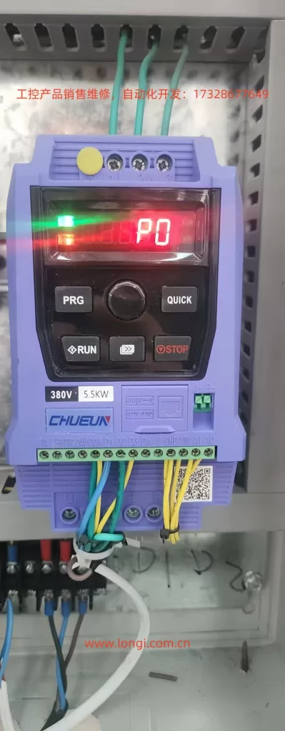
The operation panel (also known as the LED keypad or control panel) of the CHUEUN Ruikong CA100 series frequency converter is the core interface for user interaction with the device, supporting parameter viewing, modification, operation control, and fault display. The panel includes a digital display, buttons, and indicator lights, and supports the extension of an external LED or LCD keypad (using a standard network cable). The mounting hole size for the panel is 64.5mm in length × 110.5mm in width. The following is a detailed functional introduction to help users master the “CA100 operation panel usage method.”
Detailed Explanation of Operation Panel Button Functions
The button design of the CA100 operation panel is simple and practical, including the following main buttons, each of whose functions can be optimized through parameter configuration. Button operations should be performed in a safe state to avoid accidental contact while powered on.
- RUN Button: Start operation button. In keyboard control mode, pressing this button starts the forward rotation operation of the frequency converter (default direction). Suitable for quick start testing scenarios. If the frequency converter is in terminal control or communication control mode, this button is ineffective. Note: Ensure the motor is connected correctly before starting to avoid overloading.
- STOP/RESET Button: Stop/reset button. In the running state, pressing this button stops the frequency converter output; in the fault alarm state, pressing this button resets the fault. The function of this button is affected by parameter P7-27, for example, it can be set to be effective only in keyboard mode. The reset operation can clear the current fault code, but the root cause should be investigated to prevent repeated alarms.
- QUICK Button: Jog operation button or direction switching button. Depending on the setting of parameter P7-28:
- If P7-28=0, it is the jog operation button. When pressed, the frequency converter operates at the jog frequency (default 0.00Hz~50.00Hz, adjustable via parameters) and stops when released. Suitable for debugging or short-term operation.
- If P7-28=1, it is the direction switching button. After pressing, the running direction is reversed (forward to reverse, and vice versa). This function is very practical in scenarios requiring frequent rotation direction switching, such as conveyor belt control.
- PRG Button: Programming button. Pressing this button enters the parameter programming mode, allowing viewing and modification of function codes (such as P0 group basic parameters, P5 group input terminals, etc.). Press and hold to exit the programming mode. Combined with the MF.K button, it enables parameter group switching.
- MF.K Button: Multifunction button. Supports button locking and function selection, allowing the definition of the operational scope of some buttons to prevent misoperation. For example, through parameter settings, the RUN/STOP buttons can be locked, allowing only authorized users to operate.
- UP/DOWN Buttons: Up/down adjustment buttons. In programming mode, used to increase or decrease parameter values; in running mode, can adjust the digital given frequency (if the frequency source is set to digital given). The rate of change can be set via parameter P5-12 (0.01Hz/s~100.00Hz/s, default 1.00Hz/s).
The operation panel supports parameter copying. Using an LED or LCD keypad allows for quick parameter replication, suitable for batch equipment configuration. The LCD keypad is optional and supports Chinese/English/Russian prompts, enhancing international application convenience.
Detailed Explanation of Operation Panel Indicator Light Functions
The CA100 frequency converter operation panel has four indicator light groups, providing intuitive status feedback. The colors and blinking states correspond to different meanings, facilitating real-time monitoring.
- RUN Indicator Light (Running Status, Green):
- On: The frequency converter is in the running state, and the motor output is normal.
- Off: The frequency converter is in the stopped state, with no output.
- Blinking: The frequency converter is in sleep mode (energy-saving mode), suitable for fan and pump loads.
- L/D/C Indicator Light (Control Mode, Red):
- Off: Keyboard control mode (running commands come from the operation panel).
- On: Terminal control mode (running commands come from external DI terminals).
- Blinking: Remote communication control mode (running commands come from a serial port, such as Modbus).
- FWD/REV Indicator Light (Running Direction, Red):
- Off: Forward rotation state.
- On: Reverse rotation state.
- Blinking: The target frequency and actual frequency directions are opposite, or in a reverse operation prohibition state (restricted by parameter settings).
- TUNE/TC Indicator Light (Tuning/Fault/Torque Control, Red):
- On: Torque control mode (suitable for constant torque loads, such as cranes).
- Blinking: Motor parameter tuning is in progress or in a fault state. Tuning requires ensuring the motor is unloaded, and the Err code is displayed in case of a fault.
These indicator lights, combined with the LED digital display, can display parameter values, running frequencies, fault codes, etc. The display supports an input frequency resolution of 0.01Hz (digital setting) or up to the maximum frequency × 0.1% (analog setting), ensuring precise control.
How to Set and Eliminate Passwords
The CA100 frequency converter supports a user password function, implemented through parameter P7-49, to prevent unauthorized parameter modifications. The password range is 0~65535, with a default of 0 (no password). Setting a password is a key step to enhance device security, suitable for multi-user shared scenarios.
Steps to Set a Password:
- Press the PRG button to enter the programming mode, displaying P0-00 (or the current group).
- Use the UP/DOWN buttons to navigate to the P7 group (auxiliary function parameters).
- Enter P7-49 (user password), which defaults to 0.
- Enter the desired password (e.g., 1234) and press the MF.K button to confirm and save.
- Exit the programming mode. The next time you enter programming mode, you will need to enter the password to modify parameters. If the password is entered incorrectly more than a certain number of times (restricted by parameters), the Err26 (password input exceeds the limit) fault will be triggered.
Steps to Eliminate a Password:
- In programming mode, enter the current password to unlock parameter access.
- Navigate to P7-49 and set the value to 0, then press the MF.K button to confirm.
- Exit the mode. After the password is eliminated, parameters can be freely modified. Note: If you forget the password, you can restore the factory settings through parameter initialization (P7-00=1), but custom parameters will be lost.
The password function integrates automatic voltage regulation (AVR) and torque limiting to ensure safe operation. If the device is locked after password setting, it is recommended to contact a CHUEUN Ruikong agent for support.
How to Set Parameter Access Restrictions
Parameter access restrictions for the CA100 series are mainly implemented through the user password (P7-49), with no independent access level parameters (such as advanced/user level). Once the password is enabled, non-password holders can only view parameters and cannot modify them, suitable for preventing misoperation in factory environments.
Steps to Set Access Restrictions:
- Set a non-zero value for P7-49 (as described above) to enable restrictions.
- Combine with the MF.K button to lock specific buttons (the operational scope is defined by parameter P7-28).
- For advanced restrictions, set P7-00=2 (partial initialization) to retain user parameters but restrict access.
Steps to Remove Access Restrictions:
- Follow the same steps as eliminating the password. Additionally, button locking can be removed by setting P7-28=0. Parameter access restrictions help users searching for “CA100 parameter protection method” to ensure stable device operation.
This section has detailed all the functions of the CA100 operation panel, ensuring users can operate the frequency converter efficiently. Next, we will explore external control configurations.
Part 2: External Terminal Forward/Reverse Control and External Potentiometer Speed Regulation of the CA100 Frequency Converter
The CHUEUN Ruikong CA100 series supports flexible external control, including digital input (DI) terminal forward/reverse control and analog input (AI) terminal potentiometer speed regulation. The input terminals come standard with four DIs (expandable to five, with AI1 being reusable as a DI) and support NPN input mode. Implementing these functions requires setting relevant parameters and correct wiring. The following is a detailed guide suitable for users searching for “CA100 external terminal control tutorial.”
Implementing External Terminal Forward/Reverse Control
External terminal forward/reverse control switches the running command channel to terminal mode, using DI1 and DI2 to control the direction. Suitable for PLC or switch control scenarios.
Parameter Setting Steps:
- Set the running command channel to terminal control: Navigate to P0-02 (running command channel) and set it to 1 (control terminal given). The default is 0 (operation panel).
- Configure DI terminal functions:
- P5-00 (DI1 function) = 1 (forward rotation FWD).
- P5-01 (DI2 function) = 2 (reverse rotation REV).
- Set the terminal command mode P5-11:
- 0: Two-wire mode 1 (DI1 closed for forward rotation, DI2 closed for reverse rotation; both closed or open for shutdown).
- 1: Two-wire mode 2 (DI1 closed for operation, DI2 open for forward rotation, closed for reverse rotation).
- 2: Three-wire mode 1 (requires DI3=3 for three-wire control).
- 3: Three-wire mode 2 (similar but with different logic). The default is 0.
- Set the DI filtering time P5-10=0.010s (to avoid noise interference).
- Set the DI effective logic P5-13=00000 (high level effective, adjustable to low level).
Wiring for Specific Terminals:
The main circuit terminals of the CA100 include R/S/T (input), U/V/W (output to the motor), +/ – (brake). The control terminals include:
- Connect DI1 to one end of an external switch and the other end to COM (common ground).
- Connect DI2 to one end of another switch and the other end to COM.
Example: Using push-button switches, pressing DI1-COM short-circuits to start forward rotation; pressing DI2-COM short-circuits to start reverse rotation. Ensure the wire diameter complies with the manual’s recommendations (refer to the peripheral device connection section in the preface) and install a filter to avoid harmonic interference.
For models from 18kW to 30kW, DI5 expansion is supported.
After setting, press the external switches to control forward/reverse rotation. The torque response is ≤40ms, ensuring a quick response.
Implementing External Potentiometer Speed Regulation
External potentiometer speed regulation uses the AI1 analog input to adjust the frequency, suitable for manual speed control such as fan speed regulation.
Parameter Setting Steps:
- Set the frequency source to analog input: P0-03 (main frequency source) = 1 (analog voltage given) or 2 (analog current given). The default is 0 (digital given).
- Configure AI1 parameters (page 46):
- P5-15 (AI1 minimum input value) = 0.00V (corresponding to the lowest speed).
- P5-16 (AI1 minimum input corresponding setting) = 0.0% (-100.0%~100.0%, corresponding to the frequency percentage).
- P5-17 (AI1 maximum input value) = 10.00V (default).
- P5-18 (AI1 maximum input corresponding setting) = 100.0% (corresponding to the maximum frequency P0-14).
- P5-19 (AI1 input filtering time) = 0.10s (to smooth the signal).
- If an auxiliary frequency source is needed, set P0-04=1 (AI1 auxiliary).
- Ensure the running command channel is set to terminal or keyboard as required.
Wiring for Specific Terminals:
Use a 10kΩ potentiometer: Connect one end to +10V (built-in power supply), the sliding end to AI1, and the other end to GND.
Example: When the potentiometer is rotated to 0V, the frequency is 0Hz; when rotated to 10V, the frequency is the maximum (P0-14, default 50Hz).
AI1 supports voltage/current switching (via jumpers), with voltage as the default. When wiring, ensure there is no short circuit and refer to the manual for the wire diameter.
Combined with forward/reverse control, complete external operation can be achieved: terminal control for direction and potentiometer for speed regulation. Monitor the output current during testing to avoid overloading (150% rated for 60s).
Part 3: Fault Codes and Solutions for the CA100 Frequency Converter
The CA100 series frequency converter has a built-in comprehensive fault protection mechanism. When a fault occurs, an Err code is displayed, and the relay output is activated. The following lists all common fault codes (based on pages 20-24 and 31 of the manual), including cause investigation and handling countermeasures. Fault troubleshooting should be performed by professional personnel, referring to the “CA100 fault code compendium.”
Fault Code List and Solutions
| Fault Name | Code | Cause Investigation | Solution |
|---|---|---|---|
| Inverter Module Protection | Err01 | 1. U/V/W short-circuit or to ground; 2. Module overheating; 3. Loose internal wiring; 4. Board card abnormality. | 1. Eliminate the short circuit; 2. Check the fan/air duct; 3. Tighten the cables; 4. Seek support. |
| Acceleration Overcurrent | Err04 | 1. Output grounded/short-circuited; 2. Incorrect motor parameters; 3. Short acceleration time; 4. Improper V/F boost; 5. Low voltage; 6. Rotating start; 7. Sudden load addition; 8. Undersized selection. | 1. Eliminate peripheral issues; 2. Identify parameters; 3. Extend acceleration time; 4. Adjust V/F; 5. Stabilize voltage; 6. Track start; 7. Remove load; 8. Replace with higher power. |
| Deceleration Overcurrent | Err05 | 1. Output grounded/short-circuited; 2. Incorrect parameters; 3. Short deceleration time; 4. Low voltage; 5. Sudden load addition; 6. No braking; 7. High magnetic flux gain. | 1. Eliminate issues; 2. Identify parameters; 3. Extend deceleration time; 4. Stabilize voltage; 5. Remove load; 6. Add braking; 7. Reduce gain. |
| Constant Speed Overcurrent | Err06 | 1. Output grounded/short-circuited; 2. Incorrect parameters; 3. Low voltage; 4. Sudden load addition; 5. Undersized selection. | 1. Eliminate issues; 2. Identify parameters; 3. Stabilize voltage; 4. Remove load; 5. Replace with larger size. |
| Acceleration Overvoltage | Err08 | 1. High voltage; 2. External force dragging; 3. Short acceleration time; 4. No braking; 5. Incorrect parameters. | 1. Stabilize voltage; 2. Add braking; 3. Extend time; 4. Add braking unit; 5. Identify parameters. |
| Deceleration Overvoltage | Err09 | 1. High voltage; 2. External force; 3. Short deceleration time; 4. No braking. | 1. Stabilize voltage; 2. Add braking; 3. Extend time; 4. Add braking unit. |
| Constant Speed Overvoltage | Err10 | 1. High voltage; 2. External force. | 1. Stabilize voltage; 2. Add braking. |
| Undervoltage Fault | Err12 | 1. Instantaneous power failure; 2. Abnormal input voltage; 3. Abnormal bus voltage. | 1. Reset; 2. Adjust voltage; 3. Seek support. |
| Frequency Converter Overload | Err13 | 1. Heavy load; 2. Short acceleration time; 3. Stalled rotation; 4. Undersized selection. | 1. Reduce load; 2. Extend time; 3. Check motor; 4. Replace with larger size. |
| Motor Overload | Err14 | 1. Incorrect parameters; 2. Low protection threshold; 3. Heavy load. | 1. Identify parameters; 2. Adjust P9; 3. Reduce load. |
| Module Overheating | Err15 | 1. High ambient temperature; 2. Blocked air duct; 3. Faulty fan; 4. Faulty module. | 1. Cool down; 2. Clean; 3. Replace fan; 4. Seek support. |
| Current Detection Fault | Err17 | 1. Faulty detection circuit; 2. Output imbalance; 3. Abnormal drive/module. | 1. Seek support; 2. Check output; 3. Seek support. |
| Input Phase Loss | Err19 | 1. Incorrect input phase sequence; 2. Large voltage fluctuations; 3. Poor contact. | 1. Check input; 2. Stabilize voltage; 3. Tighten connections. |
| Output Phase Loss | Err20 | 1. Broken output wire; 2. Faulty motor winding; 3. Output imbalance. | 1. Check wire; 2. Check motor; 3. Seek support. |
| Motor to Ground Short-circuit | Err22 | 1. Faulty motor insulation; 2. Damaged cable. | 1. Replace motor; 2. Repair cable. |
| Motor Tuning Fault | Err23 | 1. Incorrect parameters; 2. Tuning timeout; 3. Motor not connected. | 1. Check parameters; 2. Extend P4 time; 3. Connect motor. |
| Parameter Read/Write Abnormality | Err25 | 1. Faulty EEPROM. | 1. Replace main control board. |
| Communication Fault | Err27 | 1. Upper computer not working; 2. Incorrect wiring; 3. Incorrect P8 parameters. | 1. Check upper computer; 2. Repair wiring; 3. Verify P8. |
| External Fault | Err28 | 1. DI input external signal. | 1. Reset. |
| Excessive Speed Deviation | Err29 | 1. Heavy load/short acceleration time; 2. Unreasonable P9-31/32. | 1. Extend time; 2. Reset P9. |
| User-defined Fault 1 | Err30 | 1. DI input signal. | 1. Reset. |
| User-defined Fault 2 | Err31 | 1. DI input signal. | 1. Reset. |
| PID Feedback Loss During Operation | Err32 | 1. Feedback < PA-13. | 1. Check signal/reset PA-13. |
| Quick Current Limiting | Err33 | 1. Heavy load/stalled rotation; 2. Short acceleration time. | 1. Reduce load/replace with larger size; 2. Extend time. |
| Load Loss Fault | Err34 | 1. Detection conditions reached (P9-28~30). | 1. Reset/reset parameters. |
| Input Power Fault | Err35 | 1. Abnormal voltage; 2. Frequent power on/off. | 1. Adjust voltage; 2. Extend cycle. |
| Parameter Storage Abnormality | Err37 | 1. DSP/EEPROM communication abnormality. | 1. Replace main control board; 2. Seek support. |
| Current Operation Time Reached | Err39 | 1. > P7-38. | 1. Reset. |
| Cumulative Operation Time Reached | Err40 | 1. Reached P7-20. | 1. Initialize/clear. |
| Motor Switching During Operation | Err42 | 1. Terminal switching during operation. | 1. Stop and switch. |
| Master-Slave Control Communication Disconnection | Err46 | 1. No master/slave setting; 2. Incorrect wiring/parameters. | 1. Set master; 2. Check wiring/P8. |
| SVC Stop Speed Feedback Abnormality | Err47 | 1. Parameters not learned/motor not connected. | 1. Set P9-09=0 to turn off (0~100.0s, default 5s). |
The fault address (page 31) corresponds to Modbus communication: e.g., 0004 = acceleration overcurrent. When a fault occurs, check U1-40 (current fault display). Common countermeasures include parameter identification (P4 group motor parameters), voltage stabilization, and load optimization. If the issue cannot be resolved, contact the CHUEUN Ruikong service center.
Conclusion: Optimization Suggestions for the CA100 Frequency Converter
The CHUEUN Ruikong CA100 series frequency converter, with its 150% overload capacity, 1:200 speed regulation range, and built-in PID control, is suitable for diverse applications. By following this guide, safe and efficient operation can be achieved. Regularly maintain the air duct and check the wiring. For more details, refer to the complete manual.