
An Engineering Case Study of Siemens SIMODRIVE 611 (6SN1145-1BA02-0CA2)
1. Introduction
In Siemens SIMODRIVE 611 drive systems, the infeed module plays a critical role in converting three-phase AC supply into a stable DC-link voltage that feeds all connected axis and spindle modules. Any instability in the DC-link directly affects the entire drive system and, consequently, the CNC machine tool.
A frequently reported field problem is an intermittent DC-link voltage drop, typically from around 600 VDC down to approximately 520 VDC, accompanied by spindle instability, abnormally high spindle current, and eventual machine shutdown with CNC alarms such as I311 (CCU error, e.g. C4A5 hex) and I05 (Emergency stop from machine tool).
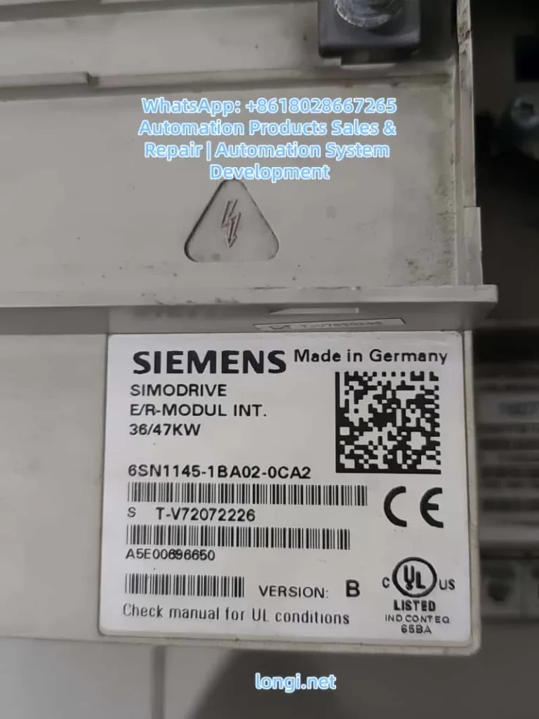
This article provides a systematic, engineering-level analysis of this fault scenario, focusing on real-world diagnostics and repair strategies rather than generic theory. The discussion is based on the SIMODRIVE 611 infeed module 6SN1145-1BA02-0CA2, but the methodology applies to most SIMODRIVE 611 configurations.
2. Typical Fault Description
The fault pattern usually presents as follows:
- DC-link voltage normally around 580–620 VDC during idle or light load
- During operation, the DC-link voltage occasionally drops to ~520 VDC
- Spindle becomes unstable, loses torque, or fails to maintain speed
- Spindle current rises sharply (often 25–30 A or higher)
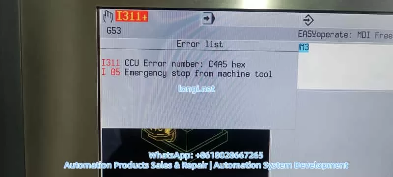
- CNC displays alarms such as:
- I311 – CCU error (hex code like C4A5)
- I05 – Emergency stop from machine tool
- After reset or power cycling, the machine may run normally for a short time before the fault reappears
Key characteristics of this fault are its intermittent nature, its strong correlation with load changes, and its tendency to worsen with temperature or operating time.
3. Why DC-Link Voltage Stability Is Critical
3.1 Role of the DC-Link in SIMODRIVE 611
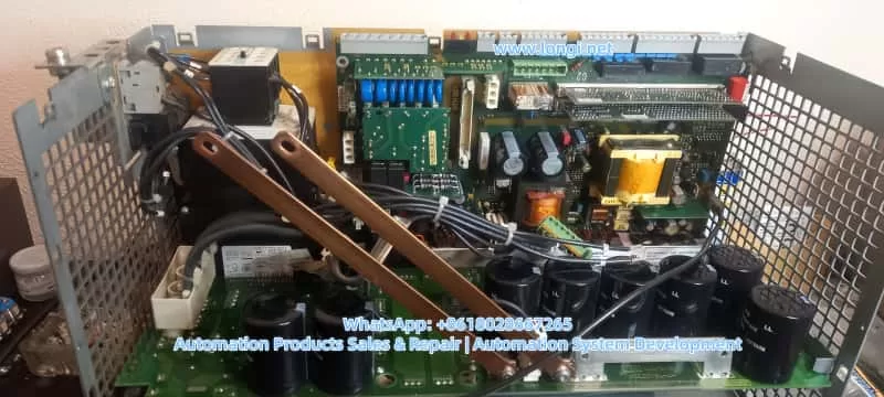
In the SIMODRIVE 611 architecture:
- The infeed module rectifies the three-phase AC supply
- A DC-link capacitor bank stores energy and smooths voltage
- All axis modules and spindle modules draw power from the shared DC-link
The DC-link acts as an energy buffer between the power grid and the inverter stages. It must absorb supply fluctuations, supply transient power during acceleration, and stabilize voltage during regenerative events.
3.2 Why Voltage Drop Causes Current Increase
Drive systems operate under a fundamental power relationship:
[
P = U \times I
]
When the DC-link voltage U drops, but the control system still demands the same mechanical output power (torque and speed), the drive compensates by increasing current I.
As a result:
- Spindle current rises rapidly
- Thermal and current limits are approached
- Protective functions are triggered
- Control units report faults and shut down the machine
In practice, high spindle current is often a symptom, not the root cause.
4. Is a Drop from 600 V to 520 V Always a Fault?
This question is essential and often misunderstood.
4.1 Relationship Between AC Input and DC-Link Voltage
Theoretical DC-link voltage after rectification depends on the AC input:
| AC Line Voltage | Typical DC-Link Voltage |
|---|---|
| 3×380 VAC | ~510–540 VDC |
| 3×400 VAC | ~540–565 VDC |
| 3×460 VAC | ~620–650 VDC |
| 3×480 VAC | ~650–680 VDC |
4.2 Practical Implications
- If the machine is supplied with 400 VAC, a DC-link of ~520 VDC under load may be electrically normal
- If the supply is 460–480 VAC, a drop from 600 V to 520 V is abnormal and indicates energy deficiency
Therefore, input voltage level must always be confirmed before diagnosing the DC-link behavior.
5. Most Probable Root Causes (Ranked by Field Experience)
5.1 AC Supply Issues: Undervoltage, Phase Loss, or Poor Connections
This is the most common cause in industrial environments.
Typical problems include:
- Loose or oxidized L1/L2/L3 terminals
- Aged or overheated fuse holders with increased contact resistance
- Worn main contactor contacts
- Momentary voltage dips caused by large machines starting nearby
Symptoms:
- Fault occurs intermittently
- Often related to plant load conditions
- Evidence of heating or discoloration on terminals or fuse holders
5.2 DC-Link Capacitor Aging (Extremely Common)
SIMODRIVE 611 systems are often 10–20 years old. DC-link electrolytic capacitors are subject to:
- High DC voltage stress
- High ripple current
- Elevated operating temperature
Over time, capacitors exhibit:
- Reduced capacitance
- Increased ESR
- Poor ripple suppression
Consequences:
- DC-link appears normal at idle
- Under acceleration or cutting load, voltage collapses rapidly
- Control system reacts with current increase and faults
In many intermittent DC-link drop cases, aging capacitors are the primary root cause.
5.3 Precharge Circuit or Main Contactor Problems
The infeed module typically includes:
- Precharge resistor
- Precharge relay
- Main contactor
If the main contactor does not fully engage or intermittently drops out:
- DC-link may momentarily rely only on stored capacitor energy
- Voltage decays rapidly under load
- CCU detects abnormal drive state
Such faults may produce audible contactor chatter or inconsistent READY signals.
5.4 Spindle or Load-Side Issues
Although less common, spindle-side faults must be considered:
- Mechanical binding or bearing failure
- Motor winding insulation degradation
- Power module partial failure
Characteristics:
- Abnormal current often appears before DC-link voltage drop
- High current may exist even at light load or no load
6. Structured Troubleshooting Procedure
6.1 Step 1: Capture Input Voltage and DC-Link Simultaneously
This is the most decisive diagnostic step.
Measurements required:
- Line-to-line voltages: L1-L2, L2-L3, L3-L1
- DC-link voltage measured directly at DC+ / DC−
- Record conditions at the moment of fault (acceleration, cutting, braking)
Interpretation:
- Input voltage drops together with DC-link → supply or connection issue
- Input voltage stable, DC-link drops → infeed module or capacitor issue
- Current spikes first → spindle or mechanical problem
6.2 Step 2: Inspect All High-Current Power Connections
With power disconnected and DC-link fully discharged:
- Tighten all power terminals and busbars
- Inspect fuse holders for heat damage
- Check main contactor contacts for erosion
- Verify cooling fans and airflow
This step alone resolves many intermittent faults.
6.3 Step 3: Evaluate DC-Link Capacitor Health
Recommended actions:
- Measure DC-link ripple voltage under load (using proper isolated methods)
- Compare voltage decay rate between idle and loaded conditions
- If necessary, remove capacitors for capacitance and ESR testing
Field experience shows that replacing the entire capacitor bank is often the most reliable long-term solution for older SIMODRIVE 611 systems.
6.4 Step 4: Verify Precharge and Contactor Control Circuits
- Check stability of contactor coil supply (often 24 VDC)
- Observe whether the contactor drops out during operation
- Inspect precharge resistor and relay for thermal stress
6.5 Step 5: Isolate and Test the Spindle Load
- Run the spindle at no load and monitor current
- Compare behavior under load and no-load conditions
- Investigate mechanical or motor issues if current is abnormally high without load
7. Understanding I311 and C4A5 Hex in Context
In SIMODRIVE 611 systems:
- I311 is a CNC-level indication of a drive system abnormality
- C4A5 (hex) is an internal diagnostic code related to drive readiness or control state
In DC-link undervoltage scenarios, these alarms are typically secondary effects, not primary causes. Once the power and energy stability issue is resolved, the alarms usually disappear without further action.
8. Repair Strategy and Preventive Maintenance
8.1 Effective Repair Actions
- Restore reliable AC supply and eliminate phase or contact issues
- Replace aged DC-link capacitor banks as a set
- Service or replace worn contactors and fuse holders
- Verify thermal management and cooling
8.2 Preventive Measures
- Periodic inspection of power connections (6–12 months)
- Thermal monitoring of capacitor banks
- Scheduled replacement of electrolytic capacitors in aging systems
- Power quality monitoring in unstable industrial grids
9. Conclusion
Intermittent DC-link voltage drops in SIMODRIVE 611 systems are rarely caused by software parameters or CNC logic. In the majority of cases, the root cause lies in:
- AC supply instability or poor power connections
- Degraded DC-link energy storage due to capacitor aging
A disciplined, measurement-based diagnostic approach—starting with voltage, not current—allows engineers to identify the true cause quickly, avoid unnecessary component replacement, and restore long-term system reliability.
Understanding the energy flow and storage behavior of the DC-link is the key to resolving these faults efficiently and permanently.