
A Practical Case Study of Fuji Electric FRENIC 4600 FM6e in Power Plant Applications
1. Background and Engineering Context
In thermal power plants, combined-cycle plants, and large industrial facilities, the condensate pump is classified as a critical auxiliary machine. Its availability directly affects unit startup, load stability, and overall plant safety. With increasing requirements for energy efficiency, soft starting, and flow control, medium-voltage variable frequency drives (MV VFDs) are widely applied to condensate pumps operating at voltage levels such as 6 kV.
This article analyzes a real-world case involving a Fuji Electric FRENIC 4600 FM6e medium-voltage VFD driving a condensate pump. The system repeatedly failed during startup, causing unplanned downtime and operational uncertainty. Through a structured engineering approach, the root causes are identified and corrective actions are proposed.
2. Description of the Field Problem
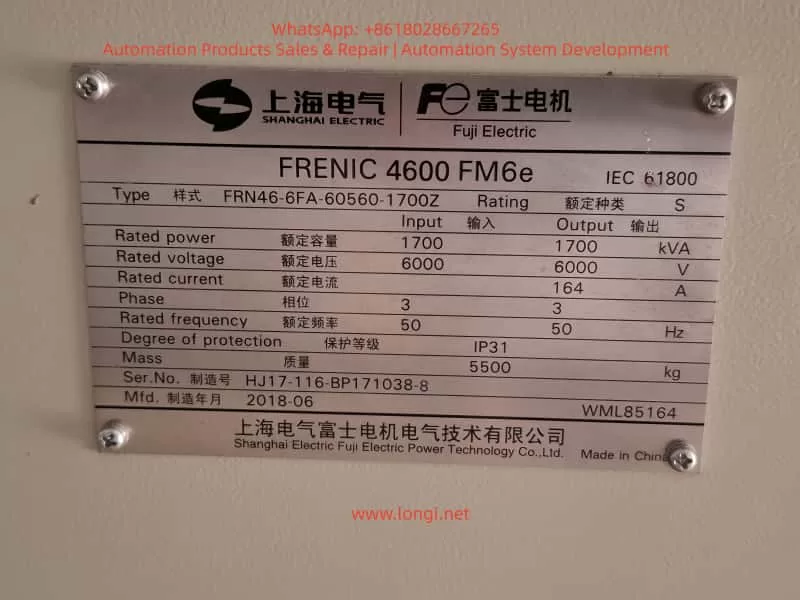
The condensate pump is driven by a 6 kV motor supplied through a Fuji FRENIC 4600 FM6e VFD rated at approximately 1700 kVA, 6 kV, and 164 A. During commissioning and operation, the following symptoms were consistently observed:
- Prior to startup, KM1 and KM2 contactors were already closed.
- When a RUN / START command was issued to the VFD:
- KM1 and KM2 opened immediately.
- The VFD stopped output and tripped.
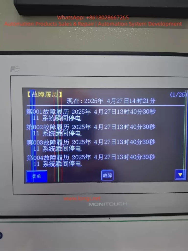
- The HMI and fault history repeatedly recorded:
Fault Code 11 – System Instantaneous Power Failure.
The fault occurred reliably at each startup attempt, preventing the condensate pump from entering normal operation.
3. Interpretation of Fault Code 11
In the Fuji FRENIC 4600 FM6e series, Fault Code 11 (System Instantaneous Power Failure) indicates that the VFD has detected a short-duration voltage drop below a predefined threshold. Typical characteristics of this fault include:
- System voltage falling below approximately 85 % of rated value.
- Duration exceeding 20 ms.
- Detection may involve not only the 6 kV main circuit, but also:
- Control power supply (AC 200/220 V),
- Breaker or contactor feedback circuits,
- System voltage detection logic.
Once detected, the VFD executes a high-priority protection sequence, which includes:
- Immediate cessation of output,
- Opening of associated contactors through interlock logic,
- Recording of a non-recoverable fault unless reset conditions are met.
4. System-Level Perspective on the Failure Mechanism
The repeated startup failure is not primarily an indication of VFD hardware damage. Instead, it reflects a system-level inconsistency during the startup process. Based on engineering analysis, the potential causes fall into four main categories.
5. Cause Category 1: Incorrect Startup Sequence and Interlock Logic
5.1 Fundamental Rule in Medium-Voltage VFD Systems
A fundamental and non-negotiable principle applies to all medium-voltage VFD installations:
The VFD circuit and the direct-on-line (bypass or line) circuit must never be energized in parallel.
Any attempt to operate both paths simultaneously can lead to:
- Severe circulating currents,
- Back-feeding of the VFD,
- Catastrophic equipment damage.
Therefore, strict electrical and logical interlocks are always implemented.
5.2 Typical Roles of KM1 and KM2
In practice, KM1 and KM2 may represent different devices depending on plant design:
- VFD input breaker or contactor,
- VFD output isolation contactor,
- Line/bypass breaker for direct-on-line operation.
If both KM1 and KM2 are closed before issuing a RUN command, the system may interpret this as a parallel or conflicting operating mode. When the VFD receives the RUN command, the interlock logic correctly responds by opening the contactors and tripping the drive.
In such cases, the VFD behavior is protective and correct, not faulty.
6. Cause Category 2: System Voltage Dip during Condensate Pump Startup
6.1 Electrical Characteristics of Condensate Pumps
Condensate pumps are typically:
- High-power loads,
- High-inertia machines,
- Sensitive to startup torque and acceleration profiles.
Even with VFD control, improper parameterization can impose significant transient stress on the power system.
6.2 Common Sources of Voltage Dip
Voltage dips during startup may be caused by:
- Insufficient upstream grid short-circuit capacity,
- Undersized transformers,
- Long medium-voltage cable runs with high impedance,
- Simultaneous starting of other large motors,
- Excessively steep VFD acceleration ramps.
If the bus voltage dips below the detection threshold, even briefly, the VFD will register a system instantaneous power failure.
7. Cause Category 3: Over-Sensitive Voltage Dip Detection Parameters
The FRENIC 4600 FM6e includes configurable parameters related to:
- System voltage dip detection enable,
- Detection threshold level,
- Drive response to detected dips (trip vs. ride-through).
If the detection threshold is set too high or ride-through functionality is disabled, the VFD may trip unnecessarily under otherwise acceptable operating conditions.
8. Cause Category 4: Control Power or Feedback Signal Instability
A frequently overlooked factor is instability in auxiliary circuits, such as:
- Control power supply voltage fluctuation (AC 200/220 V),
- Incorrect control transformer tap selection,
- Loose terminals or degraded fuses,
- Intermediate relay or contactor coil power interruptions,
- Breaker status feedback signals that momentarily drop out.
From the VFD’s perspective, any of these events can be interpreted as a system power failure.
9. Recommended Engineering Troubleshooting Strategy
9.1 Step 1: Clearly Identify the Functions of KM1 and KM2
Before modifying parameters or operating procedures:
- Review single-line and control schematics,
- Confirm whether KM1 and KM2 belong to the VFD path, bypass path, or isolation function,
- Verify interlock relationships.
Without this clarity, startup sequencing cannot be safely defined.
9.2 Step 2: Verify the Presence of Actual Voltage Dips
- Analyze DCS trends or power quality records,
- Use a voltage dip recorder on the 6 kV bus,
- Focus on the exact startup interval.
This step distinguishes grid-related issues from control logic problems.
9.3 Step 3: Optimize Startup Parameters
- Increase VFD acceleration time,
- Start from a lower initial frequency,
- Avoid simultaneous starting of other large loads.
Reducing current slew rate directly mitigates voltage dips.
9.4 Step 4: Configure Voltage Dip Ride-Through Rationally
- Enable ride-through modes where permissible,
- Adjust detection thresholds conservatively (e.g., around 80 %),
- Avoid disabling voltage detection except for controlled diagnostic purposes.
Protection functions should be preserved whenever possible.
9.5 Step 5: Inspect Control Power and Feedback Circuits
- Confirm control voltage stability within ±10 %,
- Check terminals, fuses, relays, and wiring,
- Verify reliable breaker and contactor feedback signals.
Many “high-voltage” faults originate in low-voltage control circuits.
10. Standard Procedure after Fault Occurrence
After a Fault Code 11 event:
- Disconnect main power and allow DC bus discharge,
- Reset the fault via HMI or external reset input,
- Review detailed fault history and status bits,
- Document operating conditions and sequence of events,
- Engage manufacturer technical support if faults persist.
11. Conclusion
This case study demonstrates that condensate pump startup failure in medium-voltage VFD applications is rarely caused by a single component defect. Instead, it is typically the result of interactions among:
- Startup sequence design,
- Electrical interlocks,
- Grid strength,
- Parameter configuration,
- Control power integrity.
A system-engineering mindset is essential. When analyzed holistically, Fault Code 11 becomes not an obstacle, but a valuable diagnostic signal guiding engineers toward a robust and reliable solution.