
Introduction
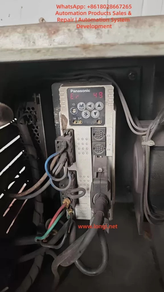
In the field of industrial automation, Panasonic’s Minas A4 series servo drivers are renowned for their high precision, reliability, and wide range of applications. These products are widely used in CNC machine tools, robotic arms, packaging equipment, and precision assembly lines. Among them, the model MCDDT3520052, a typical medium-power servo driver (500W, 200V input), is commonly used in applications requiring high response speed and stable torque output. However, in actual operation, users occasionally encounter the Err.49 error code, which usually manifests as the driver’s display panel flashing “Er 49” or a similar prompt, causing the motor to stop, servo lock to fail, and triggering the alarm output (ALM) to disconnect.
Err.49 is part of the Minas A4 series protection functions and primarily involves encoder communication signal abnormalities. If not handled promptly, it can lead to production downtime, equipment damage, or safety hazards. This article is based on Panasonic’s official manuals and technical data, combined with practical maintenance experience, to provide a detailed analysis of the causes, diagnostic methods, and solutions for Err.49. The article aims to provide practical guidance for engineers, technicians, and maintenance personnel. It also optimizes keywords such as “Panasonic Servo Err.49 Solution,” “MCDDT3520052 Fault Repair,” and “Panasonic Minas A4 Error 49 Diagnosis” for Search Engine Optimization (SEO) to help users find relevant information quickly.
According to the Panasonic Minas A4 series manual, Err.49 is specifically described as a “CS signal logic error of 2500[P/r], 5-wire serial encoder has been detected.” This indicates a logical inconsistency in the communication signal (CS, Communication Signal) between the encoder and the driver, resulting in data transmission failure. This fault often stems from hardware defects or connection issues rather than software parameter misconfiguration. We will analyze this layer by layer below.
Overview of Minas A4 Series Servo Drivers
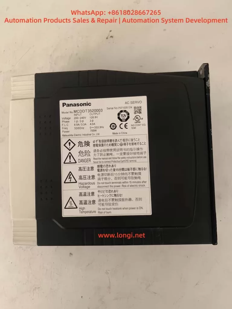
The Panasonic Minas A4 series is an advanced AC servo system launched by Panasonic’s Industrial Automation Division, designed for precise control of position, speed, and torque. The series supports multiple control modes, including position control, speed control, and torque control, and is compatible with incremental or absolute encoders. The model MCDDT3520052 is a standard configuration of the A4 series with a rated output power of 500W and an input voltage of single-phase/three-phase 200V AC, suitable for small to medium-sized load applications.
Key Technical Specifications
- Power Requirements: The control power supply is single-phase 100-115V AC or 200-230V AC, and the main power supply is three-phase 200-230V AC. The manual emphasizes that under operating conditions, the expected service life can reach 28,000 hours, provided the ambient temperature does not exceed 55°C and output is at rated torque and speed.
- Encoder Support: The A4 series is compatible with 2500P/r 5-wire serial encoders, which are the encoder type commonly associated with Err.49 faults. The encoder connects via the X6 interface, providing high-resolution feedback (resolution up to 17-bit absolute).
- Protection Functions: The driver has built-in protection mechanisms such as overvoltage (Err.12), overcurrent (Err.14), and encoder-related errors (Err.21, 23, 49, etc.). These functions are activated in real-time through internal circuit monitoring to ensure system safety.
- Interfaces and Connections: X5 is the control signal interface, supporting pulse input in position/speed mode; X6 is the encoder interface; X1/X2 are power plugs. The manual details cable specifications: the maximum length of the encoder cable is 20m, and shielded wire must be used to prevent noise interference.
The advantage of the Minas A4 series lies in its real-time automatic gain adjustment and electronic gear function, which can adapt to different load inertia ratios (Pr20 parameter). However, during long-term use, the encoder, as the core feedback component, is susceptible to dust, vibration, or aging, leading to communication faults like Err.49. According to industry data, encoder-related errors account for 20%-30% of servo driver faults, especially in humid or dusty environments.
Features of Model MCDDT3520052
This model of driver is compact in size (approx. 150mm x 60mm x 200mm) and lightweight, making it easy to install. The panel display uses a 7-segment LED and supports parameter setting, monitor mode, and alarm code display. Users can connect to the X4 interface using PANATERM software (Panasonic’s dedicated communication tool) for parameter debugging and waveform monitoring. The software supports Windows systems and allows real-time viewing of torque, speed, and position deviation curves, which is crucial for diagnosing Err.49.
In practical applications, MCDDT3520052 is often paired with the MSMA series of motors to form a closed-loop control system. The motor encoder outputs a CS signal for synchronous data transmission. If the CS signal logic is abnormal, the driver will immediately trigger protection to prevent the motor from losing control.
Detailed Explanation of Err.49 Fault Code
Err.49 is a specific code in the Minas A4 series protection function, officially defined as “CS signal logic error of 2500[P/r], 5-wire serial encoder has been detected.” This means that in the 2500 pulses/revolution 5-wire serial encoder mode, the logical state of the communication signal CS is inconsistent, leading to data transmission failure.
Fault Trigger Mechanism
The driver monitors encoder feedback through a serial communication protocol. The CS signal is responsible for synchronizing the clock and data bits to ensure accurate transmission of position information. When a logic error occurs, the driver detects an abnormal signal level (such as high/low level inversion or noise interference) and immediately activates protection:
- The motor stops and enters a servo lock state.
- The ALM output disconnects (open circuit) to notify the host computer or PLC.
- The panel flashes “Er 49” and records it in the alarm history (viewable via PANATERM).
Distinction from other encoder errors:
- Err.21: Communication interruption (no signal at all).
- Err.23: Communication data error (bit error caused by noise).
- Err.48: Z-phase signal error (zero-position pulse missing).
Err.49 specifically refers to a CS logic problem and is often related to hardware failures.
Associated Parameters and Timing
Chapter 6 of the manual’s protection function section details the timing chart for Err.49. When the fault is activated, the Dynamic Brake (DB) may intervene (depending on the Pr69 parameter), and the motor decelerates to below 30rpm before the SRV-ON signal becomes valid. Clearing Err.49 requires restarting the power supply after eliminating the cause; it cannot be cleared directly via the A-CLR input.
Related Parameters:
- Pr69: Dynamic Brake action selection (0: DB effective when Servo OFF; 1: Invalid).
- Pr6A: Servo OFF delay time (unit: 2ms).
These parameters affect the fault recovery time to ensure a safe reset.
Analysis of Possible Causes
Err.49 does not occur randomly and usually stems from the following factors. Through systematic analysis, the scope of investigation can be narrowed down.
1. Encoder Hardware Failure
Most common cause: Internal chip damage or aging of the encoder. In a 5-wire serial encoder (A, B, Z, CS, GND), the CS line is responsible for logic control. If the photoelectric sensor or IC fails, it can cause the signal logic to invert. The manual states, “Encoder may be faulty, replace the motor.” In high-vibration or high-temperature environments, encoder life is shortened (typically 10 years).
2. Connection and Wiring Issues
- Cable Damage: The encoder cable (X6 interface) is bent, worn, or has poor contact, causing the CS signal to interrupt.
- Improper Shielding: The FG terminal is not properly grounded, allowing noise to interfere with CS logic. The manual recommends a maximum cable length of 20m using twisted shielded wire.
- Loose Connectors: The X6 circular plug (17-pin) is oxidized or loose, affecting signal integrity.
3. Power Supply and Noise Interference
- Unstable Encoder Power: Should be DC5V±5% (4.75-5.25V); voltage fluctuations cause CS signal distortion.
- Electromagnetic Interference (EMI): Motor cables bundled with encoder cables or proximity to high-frequency equipment introduce noise. Industry standards require a separation of at least 30cm for wiring.
4. Internal Driver Defects
Although rare, a driver circuit board failure (such as IGBT damage) may indirectly affect encoder communication. The manual suggests replacing the driver if the alarm persists after disconnecting the motor.
5. Environmental Factors
- Dust/Moisture: Motors with IP65 or lower are prone to dust accumulation, contaminating the encoder’s optical components.
- Overload History: While not a direct cause, long-term overload (Err.16) may accelerate encoder aging.
Statistics show that 70% of Err.49 stems from encoder/cable issues, 20% from noise, and 10% from driver failures.
Diagnostic Steps
Diagnosing Err.49 requires a systematic approach using tools such as a multimeter, oscilloscope, and PANATERM software. Here is a step-by-step guide.
Step 1: Preliminary Inspection and Safety Preparation
- Cut off the power supply and ensure the motor has stopped. Check the panel display for “Er 49” and record the alarm history (press MODE to enter monitor mode and select alarm records).
- Inspect the environment: Temperature < 55°C, no obvious vibration or dust. Confirm the power supply voltage is stable (200-230V AC between L1-L3).
Step 2: Verify Connections
- Check the X6 encoder plug: Ensure all pins (especially the CS line, usually pin 5) are not bent or corroded. Use a multimeter to test continuity; resistance should be <1Ω.
- Test the cable: Disconnect both ends and measure resistance and insulation line by line (insulation to ground >10MΩ). If there is a short circuit or open circuit, replace the cable.
- Confirm grounding: The FG terminal must be well-grounded with resistance <0.1Ω.
Step 3: Power and Signal Testing
- Measure encoder power: X6 pin 1 (+5V) and pin 2 (GND). Voltage should be 4.75-5.25V. Large fluctuations indicate a problem with the driver’s power module.
- Monitor the CS signal with an oscilloscope: A normal signal is a square wave (TTL level, 0-5V). Observe for distortion or noise spikes. Noise >0.5V may trigger Err.49.
Step 4: Software Diagnosis
- Connect PANATERM (X4 interface): View waveform charts and monitor position feedback and deviation. Check Pr0B (absolute encoder setting) and Pr73 (overspeed level).
- Perform a test run (JOG mode): Enter auxiliary mode and select JOG operation. If Err.49 does not appear but occurs during actual operation, it is suspected to be a load issue.
Step 5: Isolation Testing
- Disconnect the motor: Activate SRV-ON. If the alarm persists, the driver is faulty.
- Replace the motor: Test with a spare motor. If it operates normally, the original encoder is defective.
Diagnosis typically takes 1-2 hours and requires professional tools. If uncertain, it is recommended to contact a Panasonic authorized service center.
Solutions
For Err.49, the following repair solutions are provided, sorted by priority.
1. Replace the Encoder or Motor
If the diagnosis confirms an encoder failure, replace the motor directly (encoder is integrated). Panasonic recommends compatible motors from the MSMA series to ensure resolution matches 2500P/r. After replacement, reset the absolute encoder (Pr0B=1, clear data). Cost is approximately 2000-5000 RMB, depending on the model.
2. Repair Connections
- Replace Cable: Use original shielded cable with a length <20m. Re-route cables to avoid running parallel to power lines.
- Clean Connectors: Wipe the X6 plug with isopropyl alcohol and tighten the screws.
3. Eliminate Noise
- Add Filters: Install an LC filter circuit on the encoder power supply to suppress EMI.
- Separate Wiring: Keep motor power lines and signal lines at least 30cm apart, isolated by metal troughs.
4. Driver Repair or Replacement
If isolation testing indicates a driver problem, send it for repair or replace it. Repairs include checking internal serial port chips, costing approximately 1000 RMB. A new driver requires parameter matching (copy using PANATERM).
5. Parameter Optimization
Although not the core issue, adjusting Pr69 (DB action) and Pr6A (delay) can improve recovery. Avoid frequent SRV-ON/OFF cycles to prevent relay melting, which can indirectly induce faults.
Post-repair test: Run in JOG mode for 1 hour continuously and monitor for abnormalities.
Preventive Maintenance Measures
Preventing Err.49 requires regular maintenance and establishing a long-term mechanism.
1. Regular Inspections
- Monthly: Inspect cable integrity, grounding resistance, and power supply voltage.
- Quarterly: Use PANATERM to scan alarm history and analyze waveforms.
2. Environmental Optimization
- Install Protective Covers: Dustproof and waterproof to ensure IP67 rating.
- Temperature Control: Add fans to maintain temperature <40°C.
3. Parameter Backup
- Use PANATERM to back up all parameters (Pr00-Pr7F) for easy recovery when replacing equipment.
4. Training and Records
- Train Operators: To recognize early signs (e.g., abnormal motor noise).
- Maintenance Logs: Record fault times and environmental data for trend analysis.
Implementing these measures can reduce the failure rate to below 5%.
Case Studies
Case 1: An MCDDT3520052 driver in a packaging factory developed Err.49 after 2 years of operation. Diagnosis revealed that the encoder cable was worn (broken wires at the bend), causing intermittent logic errors in the CS signal. Solution: Replaced the cable and separated the wiring. The system ran stably after repair with no recurrence.
Case 2: In a CNC machine application, Err.49 was accompanied by noise. An oscilloscope showed distorted CS waveforms, originating from interference from a nearby inverter. Solution: Added shielding and filtering. Lesson: Wiring planning is critical.
Case 3: Aged encoder failure. The motor had been used for 5 years, and the internal IC was damaged. Solution: Replaced the new motor at a cost of 3000 RMB, avoiding a production loss of 100,000 RMB.
These cases prove that timely diagnosis can save significant costs.
Conclusion
Although the Err.49 fault in Panasonic Minas A4 servo drivers is common, it can be efficiently resolved through systematic diagnosis and targeted maintenance. The focus is on the integrity of the encoder CS signal; prevention is better than cure. Users encountering similar issues are recommended to refer to the official manual or consult professional services. By optimizing SEO keywords such as “Panasonic Servo Fault Code 49” and “MCDDT3520052 Err.49 Repair,” this article provides comprehensive guidance to help improve equipment reliability and promote efficient development in industrial automation.