
Introduction
In industrial automation systems, servo drives are critical for achieving precision motion control. The Inovance IS620P series, with a power range of 100W to 7.5kW, high responsiveness, and support for multiple communication protocols (such as Modbus, CANopen, and CANlink), is widely used in semiconductor manufacturing, machine tools, food processing, and conveying machinery. However, in practical applications, the Er.400 fault, a typical alarm for DC bus overvoltage, often causes protective shutdowns, affecting production continuity. This fault usually stems from power supply anomalies, improper regenerative energy management, or incorrect parameter configurations. If not addressed promptly, it can accelerate hardware aging or trigger cascading issues. This article provides an original technical analysis of the causes, diagnostic methods, and solutions for the Er.400 fault, incorporating data from Inovance’s official manuals (IS620P Series Servo Design, Maintenance, and User Manual and IS620P(N) Common Fault Handling). Aimed at engineers and maintenance personnel, this guide emphasizes systematic troubleshooting to reduce downtime and improve equipment reliability. It also integrates industry cases and prevention strategies to optimize automation system design.
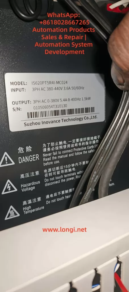
Overview of the IS620P Series Servo Drive
The Inovance IS620P series is a high-performance small-to-medium power AC servo drive designed for position, speed, and torque control, supporting multi-axis networking.
- Product Specifications: Power coverage from 100W to 7.5kW; voltage grades include 220V and 380V.
- Core Functions: Equipped with rigidity table settings, inertia identification, and vibration suppression functions. When paired with MS1/ISMH series servo motors (20-bit or 23-bit multi-turn absolute encoders), it achieves quiet, smooth, and precise positioning.
- Hardware Structure: Main circuit (R, S, T inputs; U, V, W outputs), control circuit (L1C, L2C), and communication interfaces (CN3/CN4).
- Certifications: Complies with CE standards, including EMC Directive EN 61800-3 and LVD Directive EN 61800-5-1, ensuring electromagnetic compatibility and safety.
Firmware and Fault Display:
- The IS620P series continuously optimizes its overvoltage protection logic. For example, firmware V2.0 adjusted the H02 group parameters to improve regenerative energy handling capacity.
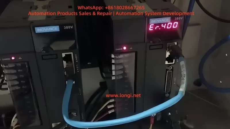
- The operation panel LED displays fault codes. Er.400 indicates that the DC bus voltage between P⊕ and – exceeds the threshold:
- 220V Grade: Normal ~310V, Fault Threshold 420V.
- 380V Grade: Normal ~540V, Fault Threshold 760V.
- Common in multi-axis systems, Er.400 frequently occurs during deceleration or power fluctuations. Internal logs are recorded via H0B group parameters, such as H0B-40 (bus voltage) and H0B-45 (internal code).
Definition and Trigger Mechanism of Er.400 Fault
According to IS620P Series Servo Design, Maintenance, and User Manual (Page 444), Er.400 is defined as DC Bus Overvoltage, where the voltage between P⊕ and – exceeds the protection threshold.
- Fault Nature: Classified as a Class 1 resettable alarm. It does not immediately damage hardware, but repeated triggering can cause capacitor degradation or increased stress on IGBT modules.
- Trigger Mechanism: Involves regenerative energy feedback. When the motor decelerates, kinetic energy is converted into electrical energy and fed back to the bus. If this energy cannot be dissipated in time (e.g., due to braking resistor failure), the voltage rises to the threshold, triggering the alarm.
Distinction from Other Faults:
- Er.410: DC Bus Undervoltage (below threshold, e.g., 380V < 480V).
- Er.920: Braking Resistor Overload (energy absorption exceeds limit).
- Er.922: External Resistor Too Small (resistance < minimum allowed).
- Note: Er.400 often correlates with Er.920, especially in high-inertia load emergency stop scenarios.
Detailed Mechanism:
- Bus Voltage Formula: Vdc=2×Vac (input effective value). Under normal 380V input, this is approximately 537Vdc.
- Regenerative Power Formula: Pregen=2×tdecJ×ω2, where J is system inertia, ω is rotational speed, and tdec is deceleration time.
- Trigger Condition: If Pregen exceeds the capacitor’s absorption capacity (approx. 100J~500J, depending on the model), the voltage peak exceeds 760Vdc (for 380V grade), triggering Er.400.
Potential Causes of Er.400 Fault
Based on IS620P(N) Common Fault Handling (Pages 34-36) and industry practices, the causes of Er.400 are categorized below. Approximately 50% stem from power issues, 30% from the braking system, 15% from parameter errors, and 5% from hardware failures.
1. Power Input Anomalies
- Excessive Input Voltage: For 380V grade, phase-to-phase voltage > 537V (effective value > 380V+10%); for 220V, > 297V. Caused by grid fluctuations, transformer faults, or peak loads.
- Incorrect Wiring: Connecting a 220V drive to a 380V source. If the drive doesn’t explode, it will immediately report Er.400 as the bus voltage instantly exceeds 420V.
- External Interference: Lightning strikes or surges causing transient high voltage, damaging the filter circuit.
2. Improper Braking Resistor Configuration
- Internal/External Resistor Failure: Open circuit (resistance ∞) or resistance value too high (H02-27 > recommended), preventing absorption of regenerative energy and causing voltage peaks.
- Energy Calculation Error: During deceleration of high-inertia loads (e.g., vertical axes), feedback energy exceeds the resistor’s power rating (H02-22). Common during emergency stops.
- Connection Issues: Loose terminals at P⊕/C or failure to remove the shorting jumper (in internal resistor mode).
3. Parameter Setting Errors
- Bus Sampling Deviation: H01-30 (gain) ≠ 100%, causing the reading to be higher than the actual value (e.g., >10V), resulting in a false alarm.
- Excessively Short Acceleration/Deceleration Times: H05-27/34 or H06-05/06 set to <100ms, leading to high peak currents and inducing overvoltage.
- Braking Parameter Mismatch: H02-25 (mode) set to 0 (internal) but an external resistor is actually used, or H02-27 > internal value (Refer to Manual Page 332).
4. Operational and Hardware Factors
- Load Anomalies: A vertical axis descending or a high-load emergency stop generates excessive feedback energy.
- Internal Drive Failure: Damaged sampling circuit or aged capacitors (in use for >5 years).
Detailed Cause Analysis Table:
| Cause Category | Specific Issue | Probability | Impact Description |
|---|---|---|---|
| Power Anomaly | Overvoltage/Wrong Wiring/Surge | 50% | Bus transient peak exceeds threshold |
| Braking Failure | Resistor Open/High Resistance | 30% | Regenerative energy has nowhere to dissipate |
| Parameter Error | Sampling Gain/Short Ramp Time | 15% | False alarm or induced trip |
| Hardware Failure | Sampling Circuit/Aged Capacitor | 5% | Persistent overvoltage |
Diagnostic Steps for Er.400 Fault
Diagnosis should follow the troubleshooting flow in IS620P(N) Common Fault Handling (Page 35), utilizing InoTouch software, a multimeter, and an oscilloscope. The process is layered, typically taking 20-60 minutes.
1. Initial Information Collection
- Check the panel for Er.400 and record the H0B-45 internal code (if it shows 1208, it indicates a chip fault).
- Use InoTouch to read the fault history (H0B-33/34) and the corresponding bus voltage (H0B-40).
- If H0B-40 > 760V (for 380V grade), overvoltage is confirmed.
- Compare H0B-26 (sampled value) with the actual measured value.
2. Power Supply Check
- Multimeter (AC Mode): Measure phase-to-phase voltage at R/S/T.
- For 380V grade, it should be between 342V and 484V. Values exceeding 537V are abnormal.
- Verify Grid Stability: Use an oscilloscope to monitor peaks. If peaks > 537V, a surge is suspected.
- Check Wiring: Confirm no incorrect connections (220V unit vs. 380V unit).
3. Bus Voltage Verification
- After powering off and waiting for the indicator light to extinguish, use a DC voltmeter to measure the voltage across P⊕/- terminals.
- Normal should be around 540V (for 380V grade). If the charged voltage > 760V, the source of regeneration must be traced.
- Software Calibration: If there is a significant deviation between the software reading and the physical measurement, adjust H01-30 to 100%.
4. Braking System Inspection
- Internal Mode (H02-25=0): Disconnect power and measure the resistance across C/D terminals. It should match the H02-23 setting (e.g., 100Ω). A reading of ∞ indicates an open circuit.
- External Mode (H02-25=1/2): Measure resistance across P⊕/C. It must be > H02-21 (minimum value, e.g., 40Ω), and the power rating must exceed H02-22.
- Energy Calculation: Estimate Pregen using the formula. If it exceeds the resistor’s capacity, an upgrade is needed.
5. Parameter and Operational Testing
- Review Parameter Groups:
- H02 Group (Braking): Check mode and resistance settings.
- H05/H06 Groups (Ramps): Increase deceleration time to 500ms for testing.
- Simulated Operation: Run at low speed and perform an emergency stop. Observe the H0B-40 waveform in InoTouch. If the peak is too high, the curve needs optimization.
- Multi-axis Systems: Check synchronization. Uneven energy distribution among axes can induce faults.
6. Advanced Troubleshooting
- Interference Test: Install an SPD (Surge Protective Device) or isolation transformer, then restart and observe.
- Hardware Diagnosis: If resetting fails repeatedly, internal damage (IGBT or capacitor) is suspected. Replace with a spare drive for testing.
Diagnostic Flowchart Overview:
Start → Collect Logs (H0B) → Power Voltage OK? → Yes → Bus Measured OK? → Yes → Check Braking Resistor → Adjust Parameters → Replace Hardware
Solutions for Er.400 Fault
Here are step-by-step measures targeting the identified causes. Approximately 80% of issues can be resolved on-site, referencing the handling table on Page 36 of the manual.
1. Handling Power Anomalies
- Excessive Voltage: Install a voltage stabilizer or UPS to ensure the effective grid voltage remains < 484V.
- Incorrect Wiring: Power off immediately. Replace with a matching power supply or drive. If hardware is damaged (e.g., “blown up”), replace the bus capacitors or the entire unit.
- Lightning/Surge: Install a Surge Protective Device (SPD) and ensure the PE ground terminal is reliably connected (grounding resistance < 4Ω).
2. Optimizing the Braking System
- Resistor Failure:
- If the internal resistor is damaged, switch to external mode (H02-25=1). Remove the shorting jumper between P/D and connect wires to P⊕/C.
- Selection Criteria: Resistance value should equal the H02-23 recommended value. Power rating should be at least 1.5 times the calculated value.
- Energy Overload: Upgrade the resistor’s power rating or install multiple resistors in parallel (ensure total resistance remains > H02-21 minimum).
- Connection Repair: Tighten terminal screws to ensure no loose connections.
3. Parameter Adjustments
- Restore Factory/Calibrate: Set H01-30 = 100% (bus voltage gain) and H02-27 to the manual’s recommended resistance value.
- Extend Deceleration Time: Set H06-05/06 to 500ms~1000ms. Save parameters and restart (H0A-00=1).
- Mode Switching: For high-load vertical applications, set H02-25=2 (External Braking High Power Mode).
4. Operational and Hardware Repairs
- Load Optimization: Add counterweights to vertical axes or use S-curve smoothing in the command profile to soften deceleration.
- Drive Replacement: If hardware damage is confirmed, back up parameters and migrate them to the new unit. Replace aged capacitors professionally if necessary.
Common Parameter Adjustment Table:
| Parameter | Description | Recommended Value | Effect |
|---|---|---|---|
| H02-25 | Braking Resistor Mode | 1 (External) | Immediate/Restart |
| H02-27 | External Resistor Resistance | Match actual resistor (Ω) | Restart Required |
| H01-30 | Bus Voltage Sampling Gain | 100% | Immediate |
| H06-05 | Motor Acceleration Time | ≥500ms | Takes effect during run |
| H06-06 | Motor Deceleration Time | ≥500ms | Takes effect during run |
Reset Method: Disconnect main power for 10 seconds and re-energize, or trigger a hardware reset via the DI port assigned to FunIN.8 (high level trigger).
Preventive Measures for Er.400 Fault
Prevention is better than cure. Refer to the manual’s certification information and installation requirements for the following strategies.
- Design Phase:
- Calculate system regenerative energy accurately. Select an external braking resistor with a power rating >1.5 times the motor’s rated power.
- Add line reactors or filters on the power supply side to ensure grid voltage deviation <10%.
- Installation Best Practices:
- Separate high-power and low-power wiring by >30cm to avoid interference.
- Use shielded twisted pairs for control cables, keeping length <50m. Ground both ends of the shield. Add a 120Ω termination resistor for CAN bus.
- Maintenance Strategy:
- Quarterly Inspections: Measure input voltage and braking resistor resistance.
- Software Monitoring: Use InoTouch to monitor H0B-12 (load rate), ensuring it stays <80%.
- Firmware Updates: Update drive firmware to V2.0 or later.
- Risk Management:
- Install SPDs in areas with high lightning activity.
- Train personnel on parameter standardization to prevent accidental modifications.
Implementing comprehensive preventive measures can reduce the Er.400 fault rate to <3%.
Case Studies
Case 1: Machine Tool Application
- Symptom: An IS620P drive (380V grade) triggered Er.400 during an emergency stop.
- Diagnosis: Measured input voltage peak reached 580V (unstable grid), and the braking resistor was 150Ω (too high; manual recommends 50Ω).
- Solution: Installed a stabilizer, replaced the resistor with a 50Ω external unit, and extended deceleration time to 500ms.
- Result: System stabilized, reducing monthly downtime by 20 hours.
Case 2: Food Conveyor Line
- Symptom: A multi-axis system frequently reported Er.400, with some drives exploding.
- Diagnosis: Found that a 220V drive was incorrectly wired to a 380V source. Bus voltage instantly reached 750V.
- Solution: Replaced drives with matching 380V units and installed a phase sequence protector.
- Result: Faults were eliminated entirely, improving line efficiency by 10%.
Case 3: Semiconductor Equipment (High Inertia)
- Symptom: Er.400 occurred during emergency stops of a vertical axis.
- Diagnosis: Calculated regenerative energy far exceeded the internal resistor’s capacity (approx. 2000J).
- Solution: Switched to external braking mode (H02-25=1), installed a 200Ω/2000W resistor, and set H02-27=200Ω.
- Result: With preventive maintenance (quarterly resistance checks), zero alarms were recorded.
Related Parameters, Tools, and Extended Knowledge
Key Parameter Groups Quick Reference
- H0B Group: Fault logs (H0B-40 is real-time bus voltage; H0B-45 is internal error code).
- H02 Group: Braking unit settings (H02-21 min resistance, H02-22 braking power, H02-25 braking mode).
- H01 Group: Basic parameters (H01-30 is bus voltage sampling gain).
- H05/H06 Groups: Speed loop and acceleration/deceleration time constants.
Recommended Tools
- InoTouch Software: For parameter editing, real-time monitoring, and reading fault logs.
- High-Precision Multimeter/Oscilloscope: For measuring voltage, waveforms, and resistance.
- CAN Bus Analyzer: If the fault is induced by communication interference, CANlink signal quality must be checked.
Extended Knowledge
- Associated Faults: Er.400 may occur concurrently with Er.d04 (Communication Timeout), as overvoltage interference can corrupt communication data.
- Future Trends: Newer firmware may integrate AI prediction algorithms to monitor bus voltage trends and adjust braking strategies proactively to avoid hard alarms.
Conclusion
While the Er.400 fault in the Inovance IS620P servo drive can disrupt production, it can be efficiently resolved through systematic power supply checks, braking system optimization, and parameter corrections. Understanding the dynamic balance of the DC bus is key to solving this issue. Users should focus on preventative design and regular maintenance to minimize downtime risks. As automation deepens, mastering these troubleshooting techniques will significantly enhance equipment operational efficiency and reliability.