Posted on

Technical Guide: PowerFlex 400 Inverter Fault 032 – Fan Feedback Loss Repair Case and Drive Power Supply Abnormal Voltage Analysis

The Allen-Bradley PowerFlex 400 series of inverters are widely used in the Heating, Ventilation, and Air Conditioning (HVAC) industry, especially in a large number of fan and pump applications. Therefore, accumulating repair techniques and experience in fault location is of great importance. After continuous operation for many years, issues such as aging of internal fans and low-voltage capacitors, and increased power supply ripple in the inverter can easily lead to control failures. Among them, fan faults and drive power supply aging are high-frequency fault points. This article systematically discusses a real-world case where a PowerFlex 400 inverter displayed the FAULT 032: Fan Feedback Loss, covering multiple aspects.

PowerFlex 400 drive board

I. Fault Background and Initial Assessment

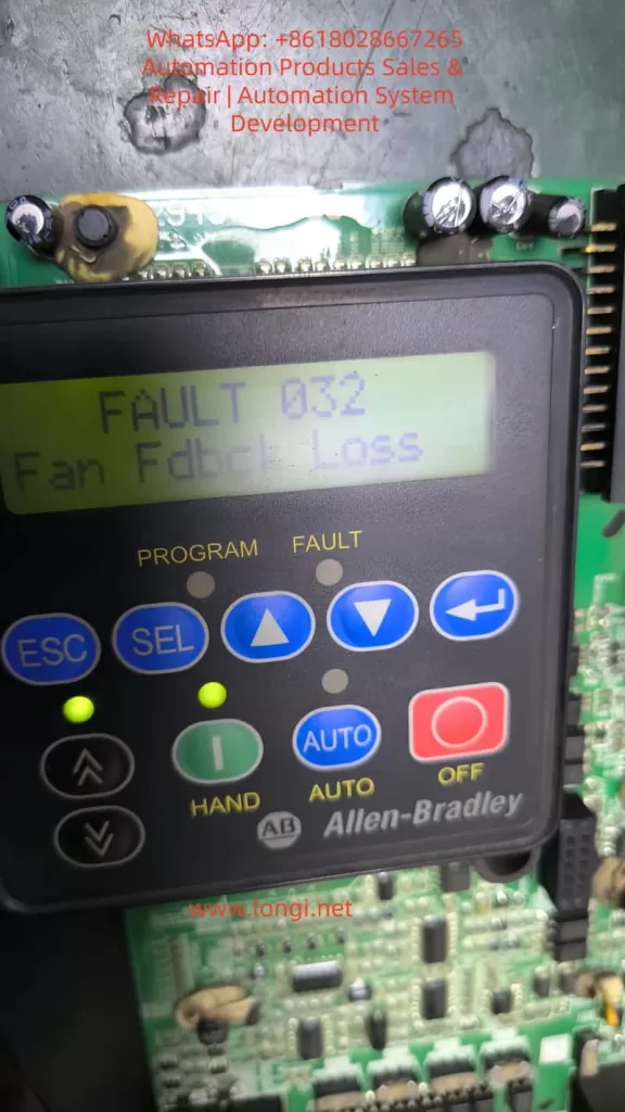
An Allen-Bradley PowerFlex 400 inverter sent in for repair by a customer failed to operate after power-on self-test, with the keypad display showing the alarm:

FAULT 032
Fan Fdbck Loss
This alarm indicates that the main board has detected that the fan control output has been activated, but the feedback signal has not been received or the signal form is non-compliant. The fans in PowerFlex 400 are mostly of three-wire or four-wire design. In addition to power supply, they also provide a Tach/FG feedback signal (generally in the form of an open-collector pulse output). The inverter determines the fan speed by sampling the pulse frequency. If the Microcontroller Unit (MCU) does not detect feedback changes within a set time, fault 032 is triggered. On-site inspection revealed that the fan was damaged, with severe shaft seizure and no signal output from the speed feedback, clearly identifying the cause of the fault.

II. Fan Repair and Extended Issues

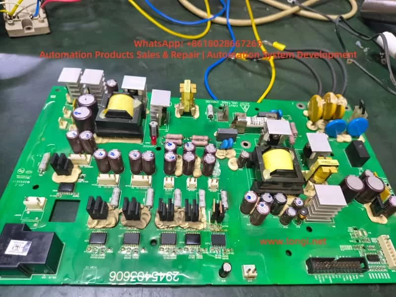
After replacing or repairing the fan, the inverter passed the power-on self-test. However, the repair engineer noticed that the thermal grease in the temperature control area of the control board was aged and the tops of the capacitors were bulging, prompting a further in-depth inspection. The PowerFlex 400 adopts a zoned power supply structure. Long-term operation with a fan fault can lead to an increase in the temperature of the control board, causing an increase in the Equivalent Series Resistance (ESR) of the capacitors in the low-voltage power supply circuit and deterioration of ripple, resulting in drive voltage drift. Therefore, although the fan alarm has been eliminated, potential power supply degradation risks need to be investigated. Otherwise, the inverter may fail again during high-load or long-term operation, or even damage the IGBT drive unit.

III. Analysis of the Circuit Structure in the Low-Voltage Power Supply Drive Area

The control board of the PowerFlex 400 generally has the following low-voltage power supplies:

Voltage LevelTypical Function
5V DCMCU, communication, logic sampling
9 – 12V DCFront-stage drive buffering, fan drive, and detection-related circuits
15 – 18V DCIGBT drive, optocoupler bias power supply
24V DCRelays, solenoid valves, external IO power supply

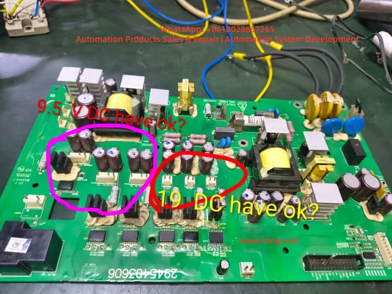
When repairing, the engineer removed the drive board and marked two key voltage areas:

  • The area marked with a pink circle on the left measured 9.5V DC.
  • The area marked with a red circle in the middle measured 19V DC.

Whether these two voltages are reasonable and within the normal operating range needs to be comprehensively judged from the perspectives of voltage regulation structure, load conditions, and capacitor health status.

Voltage values of the PowerFlex 400 drive board

IV. Technical Analysis of Test Data

1. Analysis of the 9.5V DC Measurement Result

This area is adjacent to multiple small filter capacitors, Schottky rectifiers, and three-terminal voltage regulators, and belongs to the low-voltage DC voltage regulation output area. Under normal circumstances, it may be:

  • A 9V or 10V regulated output (corresponding to 9.5V, which is within the normal tolerance range).
  • It may also be designed for a target of 12V, but the voltage has dropped to 9.5V due to capacitor aging.
    The determination methods are as follows:
Test MethodDetermination Basis
Measure 9.5V with no load and a significant voltage drop under loadIndicates an increase in capacitor ESR or weakened voltage regulation
Ripple on the oscilloscope > 100mVIndicates capacitor degradation and the need for replacement
Insufficient fan speed and irregular feedback waveform after loading the fanIndicates insufficient power supply capacity

If the original design was for 12V, the inverter may intermittently alarm and have unstable drive under heavy load conditions, and it cannot be directly considered that 9.5V is completely normal.
Conclusion: 9.5V is acceptable, but its health status needs to be further confirmed by combining ripple and load voltage drop measurements. It is recommended to replace all the capacitors in this area.

2. Analysis of the 19V DC Measurement Result

The presence of 19V in the drive power supply area is worthy of attention. The common voltages on the drive side of PowerFlex are:

  • 15V, 16V, and 18V are the most common.
  • A voltage exceeding 19V is close to the voltage tolerance boundary of the components. If it continues to rise, it may break down the drive optocoupler or gate resistor.
    If the voltage regulation target here is 18V, then 19V is on the high side. Possible reasons include:
  • Parameter drift of the voltage regulation diode.
  • Aging of the filter capacitor, causing the power supply peak to rise.
  • Failure of the feedback sampling resistor.
    Voltage spikes under no-load conditions are common, but the voltage should drop under load.
    The following tests must be carried out:
  • Whether the voltage drops to 17 ± 1V under load.
  • Whether there are spikes in the waveform.
  • Whether the temperature of the voltage regulation chip is abnormal.
    Conclusion: Although the inverter may not directly report an error when operating at 19V, there are potential risks for long-term operation. The voltage regulation chain should be thoroughly investigated, and aging capacitors should be replaced.

V. Systematic Repair Recommendation Process

To ensure long-term repair reliability, it is recommended to follow the following sequence for step-by-step handling:

Step 1: Fan Feedback Verification (Core of Fault 032)

ItemConfirmation Method
Whether the fan power supply is stableMeasure the fan VCC voltage
Whether the feedback signal existsDetect the FG/TACH waveform with an oscilloscope
Whether the MCU sampling end is unobstructedConfirm the channel resistance, capacitors, and pull-up resistors

If the pulse frequency is normal, fault 032 will not recur.

Step 2: In-Depth Detection of the Low-Voltage Power Supply

Measure 9.5V and 19V under no-load, fan load, and whole-machine operation conditions respectively.
Observe the voltage drop and fluctuation range.
If the tops of the capacitors are bulging, it is recommended to replace all the capacitors in the area (the capacitor aging situation on this board is obvious).
Empirical judgment: For PowerFlex inverters that have been in operation for many years, 70% of the faults are related to capacitors. Replacing all the capacitors at once is more cost-effective and reliable than testing each capacitor individually.

Step 3: Health Assessment of the Drive Circuit

  • Check whether the IGBT drive optocouplers are aged.
  • Test whether the rising and falling edges of the gate waveform are symmetrical.
  • If the voltage drop capability of 19V is poor, replace the voltage regulation diode and filter capacitors.

Step 4: Reassembly and Load Run Test

Run the inverter for at least half an hour to verify:

  • Whether the fan feedback alarm recurs.
  • Whether the drive temperature rise is normal.
  • Whether there are output waveform glitches or abnormal noises.
    Only after passing the test can the inverter be delivered for use.

VI. Technical Summary and Experience Extraction

  • Fault 032 is mostly caused by fan damage or loss of feedback signal. Repairing the fan or restoring the feedback signal path can eliminate the alarm.
  • Fan faults are often accompanied by an increase in the temperature rise of the control board. After the fan stops rotating, the internal temperature increases, accelerating capacitor aging, and power supply voltage drift may follow.
  • Although 9.5V and 19V can operate, the voltage regulation target values need to be evaluated. In particular, a high voltage in the drive area may affect component lifespan, and the ripple and load performance should be tested.
  • Preventive replacement of capacitors is a key operation to improve repair success rate and reliability. Batch replacement of capacitors on the PowerFlex control board helps ensure long-term stable operation.
  • Repairs must proceed step by step from fan feedback → low-voltage power supply → drive chain → whole-machine baking and run test to avoid only addressing surface faults while ignoring the root cause and forming rework.

Conclusion

This article is based on a real repair case of a PowerFlex 400 inverter with a fan feedback alarm and abnormal drive power supply voltage. Through voltage test judgment logic, voltage regulation circuit analysis, acceptable operating range determination, and fault extension explanations, it provides a complete set of repair methods that can be directly referenced from both theoretical and practical perspectives. It is hoped that this article can provide clear directions for more electrical repair engineers when dealing with similar inverter faults, improve diagnostic efficiency, reduce the number of disassemblies and assemblies, and achieve the goal of successful first-time repairs.

Posted on

Deep Dive into Allen-Bradley PowerFlex 400 Fault 032: From Internal Logic to Advanced Maintenance Strategies

Introduction: The Guardian of Thermal Management

In the landscape of industrial automation, the Allen-Bradley PowerFlex 400 AC drive is a staple for Fan & Pump applications, optimized for HVAC, water treatment, and building automation. In these critical environments, system stability is not just about energy efficiency—it is a cornerstone of operational safety.

Among the various diagnostic codes, Fault 032 (F032) is one of the most significant yet misunderstood signals. It is more than a simple error; it is an urgent “SOS” from the drive’s thermal management system. This article provides a comprehensive analysis of the F032 fault, covering its underlying mechanisms, diagnostic logic, and a full-spectrum solution for maintenance engineers.


fault 032 fan fdbck loss

Chapter 1: Decoding F032 – The Critical Role of Fan Feedback

1.1 Defining the Fault

According to the PowerFlex 400 User Manual, F032 stands for “Fan Fdbck Loss.” This indicates that the drive has detected an inconsistency between the commanded state of the cooling fan and the actual speed feedback received by the control board.

This fault is specific to higher-power units, particularly those in Frame D and Frame E sizes. Unlike smaller drives that use simple “always-on” fans, these larger frames utilize a closed-loop monitoring system. The drive provides power to the fan and monitors a dedicated feedback line (usually a Hall-effect sensor signal) to verify rotation. If the drive expects the fan to spin but detects no pulses, it triggers an F032 trip to prevent the catastrophic failure of power components like IGBTs.

1.2 Why Only Large Frames?

Smaller units (Frame C) often rely on simpler cooling structures or auxiliary fans without feedback. However, Frames D and E integrate high-density power modules that generate significant heat. These frames require high-performance feedback-controlled fans to ensure cooling redundancy and safety.


Chapter 2: The Physical Logic of Thermal Management

2.1 The Enemy of Semiconductors: Heat

The core of the drive is the IGBT (Insulated Gate Bipolar Transistor). During high-speed switching, IGBTs generate substantial thermal energy through switching and conduction losses. If the heatsink’s heat is not extracted by the fan, the junction temperature rises rapidly. Exceeding the critical limit (typically 125°C–150°C) results in irreversible physical damage to the semiconductor structure.

2.2 Framework and Airflow Design

PowerFlex 400 is categorized by Frame Sizes to simplify maintenance.

  • Frame D & E: These models feature powerful cooling fans located at the top or bottom. Their internal air ducts are designed for high-velocity vertical airflow, making the fan the single most critical component for hardware longevity.

Chapter 3: Multi-Dimensional Root Cause Analysis

When F032 appears, an engineer must use a “layered” diagnostic approach, moving from physical to electrical causes.

3.1 Physical Layer: Obstruction and Wear

  • Mechanical Blockage: Cotton lint, dust buildup, or debris (like stray cable ties) can physically jam the fan blades.
  • Bearing Failure: In high-temperature environments, bearing grease can dry out or carbonize, leading to increased friction, reduced speed, or a total seize-up of the motor.

3.2 Electrical Layer: Connections and Signals

  • Loose Connectors: Constant micro-vibrations in industrial settings can cause the fan’s plug to drift from the control board socket.
  • Feedback Circuit Failure: The internal Hall sensor within the fan may fail. In this case, the fan might physically spin, but the drive “sees” no speed pulses.
  • Power Supply Issues: The Switched-Mode Power Supply (SMPS) providing 24V DC to the fan may experience voltage drops or failure.

3.3 Environmental Layer: Installation Layout

If the drive is installed in a space with insufficient clearance, backpressure increases. This forces the fan to work harder, potentially leading to speed fluctuations that trigger the feedback loss fault.


powerflex 400

Chapter 4: Step-by-Step Diagnostic and Troubleshooting

Safety Warning: Before any disassembly, disconnect all power and wait at least 3 minutes for the bus capacitors to discharge to safe levels.

Step 1: Preliminary Visual and Manual Inspection

  1. Isolate Power: Lock out and tag out the input power.
  2. Access the Fan:
    • Frame D: Loosen the two cover screws and pull the cover bottom out and up.
    • Frame E: Loosen the four cover screws and pull the cover out and up.
  3. Manual Rotation: Spin the fan blades by hand. They should move freely. If you feel resistance or hear grinding, the fan must be replaced.

Step 2: Connection Integrity Check

  1. Locate the fan’s wiring harness connected to the main control board.
  2. Unplug the connector and inspect the pins for oxidation, corrosion, or burning.
  3. Reseat the connector firmly until it clicks into place.

Step 3: Voltage Measurement

  1. With the drive safely energized (following proper safety protocols), measure the DC voltage at the fan power terminals.
  2. A healthy PowerFlex 400 should provide a steady 24V DC.
  3. If 24V is present but the fan does not spin, the fan motor is defective.

Step 4: Pulse Signal Testing (Advanced)

Using an oscilloscope, you can probe the feedback line. A functional fan will produce a continuous square wave signal while spinning. A flat line (high or low) indicates a failed Hall sensor.


Chapter 5: Component Replacement and System Reset

5.1 Replacement Essentials

If the fan is confirmed faulty, it must be replaced with an identical OEM specification part. Pay close attention to airflow direction (usually indicated by an arrow on the fan housing). Installing the fan backward will cause heat to build up, leading to an immediate over-temperature trip.

5.2 Clearing the Fault

Once the hardware issue is resolved, reset the drive via:

  1. HIM Keypad: Press the Stop/Reset key.
  2. Power Cycle: Turn off the input power completely and restart.
  3. Parameter Reset: Set Parameter A197 [Fault Clear] to 1 or 2.
  4. Auto-Restart: If appropriate for your application, adjust A163 [Auto Rstrt Tries] and A164 [Auto Rstrt Delay].

Chapter 6: Preventative Maintenance Strategies

6.1 Environmental Optimization

  • Dust Mitigation: Regular cleaning of the drive’s air intake is the best way to protect the fan.
  • Ambient Control: Ensure the air temperature stays within the -10°C to 45°C range. In harsh environments, consider a NEMA 12 enclosure with filtered ventilation.

6.2 Lifecycle Management

Cooling fans are consumable parts. Following industry guidelines for solid-state controllers, it is recommended to proactively replace fans every 3 to 5 years, depending on the duty cycle and environment.


Conclusion

Fault 032 is a vital protective logic that ensures the longevity of your PowerFlex 400. By understanding the relationship between the physical rotation of the fan and the electronic feedback expected by the drive, engineers can move beyond “guessing” and implement precise, logical repairs. Regular maintenance and environmental awareness are the keys to ensuring your drive—and your facility—stays cool and operational.

Posted on

User Manual Guide for Rockwell PowerFlex 400 Series Variable Frequency Drive

I. Function Introduction and Parameter Setting of the Operation Panel (Numeric Keypad)

The PowerFlex 400 Series Variable Frequency Drive (VFD) is equipped with an intuitive operation panel. Users can easily complete parameter settings, monitor operating status, and perform fault diagnosis through the numeric keypad. The main keys on the operation panel include the Increment Key, Decrement Key, PRG Function/Data Toggle Key, STOP Key, SET/Data Confirmation Key, and MF.K/Multi-Function Key.

Powerflex 400 numeric keypad function diagram

Password Setting and Parameter Modification Restriction:

After entering the parameter editing mode, users can set a password to restrict parameter modifications by selecting a specific parameter (e.g., P042). Once the password is set, unauthorized users will be unable to change the protected parameters.

To eliminate the password, simply set the password parameter (P042) to 0 and save the changes.

Restoring Factory Default Parameters:

With the VFD in the stopped state, press the programming key to enter the menu, select the F0.13 function to restore parameters, change the current value to 2, and press the confirmation key to save. This will restore all parameters to their factory defaults, eliminating any user-defined settings.

II. External Terminal Control for Forward/Reverse Operation and Potentiometer Speed Adjustment Settings

Forward/Reverse Control:

The PowerFlex 400 Series VFD supports forward/reverse control of the motor through external terminals. The specific setting parameters are T051 to T054, which define the functions of the multi-function input terminals. For example, set T051 to 1 (forward operation) and T052 to 2 (reverse operation), and then connect the corresponding external switches or relays to the respective input terminals to achieve forward/reverse control of the motor.

Potentiometer Speed Adjustment:

Potentiometer speed adjustment is a common analog speed control method. First, configure the VFD’s analog input terminals (e.g., AI1 or AI2) to accept voltage or current signals from the potentiometer. This can be achieved by setting parameters T069 or T073 to select the corresponding input range and signal type (e.g., 0-10V voltage or 4-20mA current). When wiring, connect the sliding end of the potentiometer to the VFD’s analog input terminal and the fixed ends to the power supply and ground respectively.

Powerflex 400 External Terminal Control Diagram

III. Analysis of Fault Codes and Solutions

The PowerFlex 400 Series VFD features comprehensive fault diagnosis capabilities. When a fault occurs, the VFD displays the corresponding fault code. Below are some common fault codes, their meanings, and solutions:

  • F36: Output Overcurrent. Possible causes include motor overload, output short circuit, or improper parameter settings. Solutions include checking motor load, inspecting the output circuit, and adjusting relevant parameters (e.g., P033 motor overload current setting).
  • Drive-HIM: Drive Alarm. Typically caused by EEPROM checksum errors. Solutions include power cycling or replacing the HIM module.
  • F22: Drive Reset Fault. May occur during power-up or operation. The solution is to check the correctness of the wiring, especially the connections at the TB2 terminal.
  • F32: EEPROM Fault. May be due to corrupted EEPROM data or inability to program valid data. Solutions include checking the connection between the main control board and the power board, resetting to default parameters, and power cycling.

IV. Summary

The Rockwell PowerFlex 400 Series VFD, with its powerful functions, flexible configuration, and reliable performance, is widely used in the field of industrial automation. Through the introduction in this article, users can better understand and master the functions of the VFD’s operation panel, external terminal control settings, fault diagnosis, and solutions, thereby ensuring safe and efficient operation of the VFD. Whether for users who are new to VFDs or experienced engineers, this user manual provides valuable information and practical operating tips. In practical applications, it is recommended that users configure VFD parameters based on specific application scenarios and needs, and regularly inspect and maintain the VFD to extend its service life and improve production efficiency.