Introduction
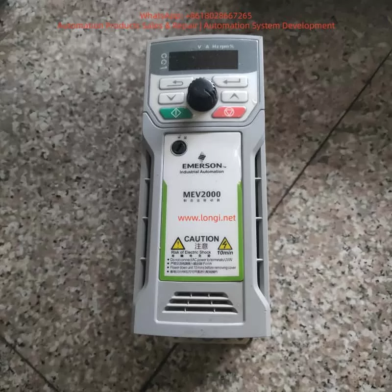
The MEV2000 series inverter is a high-performance industrial drive developed by Nidec Control Techniques (formerly Emerson). It is widely applied in fan, pump, conveyor, and textile machinery systems. While the MEV2000 series is known for its robust design and advanced vector control capability, hardware-level faults can still occur under harsh operating conditions. Among these, fault code Er.0110 is a critical alarm typically associated with large-frame models and indicates internal hardware abnormalities.
This article provides a systematic technical analysis of the MEV2000 inverter, its working principles, installation standards, parameter configuration, common fault types, and focuses in depth on the diagnosis and maintenance strategy for Er.0110 hardware faults.
1. Overview of the MEV2000 Series Inverter
The MEV2000 series inverter is designed for industrial motor control applications, supporting both induction motors and permanent magnet synchronous motors. It integrates vector control and V/F control technologies to meet various load requirements.
Key specifications include:
- Power range: 0.37 kW to 250 kW
- Voltage classes: 200 V, 400 V, 575 V
- Control modes: V/F, open-loop vector, closed-loop vector
- Built-in EMC filter, RS485 communication interface, and PID controller
- Modular architecture supporting remote keypad, SD card adapter, and Ethernet options
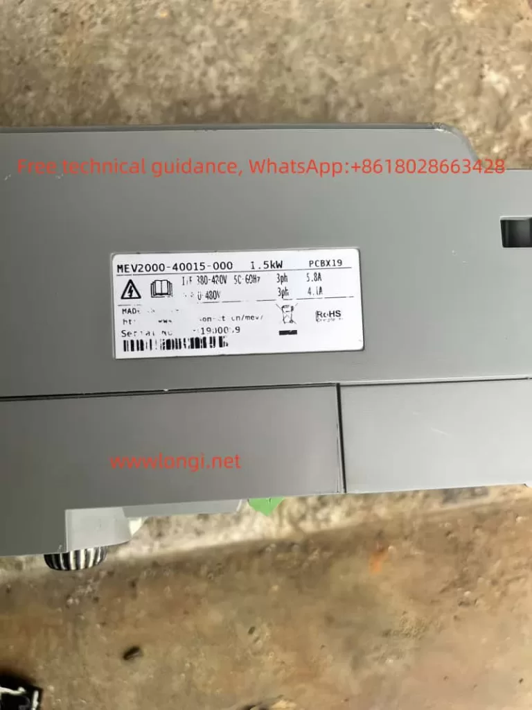
For example, the MEV2000-400-0011 model delivers a continuous output current of 1.1 A and up to 1.65 A in heavy-duty mode. The product complies with IEC 61800-3 EMC standards and has an IP20 protection rating, upgradeable to IP66 using enclosure options.
The drive integrates overload protection, short-circuit monitoring, and thermal modeling, making it suitable for pumps, fans, conveyors, and textile machinery.
2. Operating Principle and Control Technology
The inverter converts fixed-frequency AC power into variable-frequency, variable-voltage output using PWM (Pulse Width Modulation) technology. Internally, the MEV2000 consists of a rectifier, DC bus, capacitor bank, inverter bridge, and control board.
- AC input is rectified to DC.
- DC bus capacitors stabilize the voltage (typically ~565 V for 400 V models).
- IGBT inverter modules generate three-phase PWM waveforms.
The inverter uses Space Vector Modulation (SVM) to improve harmonic performance and energy efficiency. Under vector control, torque and flux are independently regulated using Park transformation algorithms. Rotor position is obtained via encoder feedback or sensorless estimation.
In V/F mode, voltage-frequency ratio is maintained constant, with low-frequency voltage compensation to prevent torque loss. Built-in PID functions allow closed-loop control for pressure, flow, and tension systems. Communication is based on Modbus RTU, supporting baud rates up to 38.4 kbps for PLC and SCADA integration.
3. Installation and Wiring Standards
Recommended installation environment:
- Temperature: –10 °C to 50 °C
- Humidity: <95% RH, non-condensing
- Free from corrosive gas, oil mist, and vibration
Wall-mounted installation requires at least 100 mm top clearance and 150 mm bottom clearance. For panel installation, forced ventilation is recommended.
Main circuit wiring guidelines:
- L1/L2/L3: AC input
- U/V/W: Motor output
- PE: Protective earth (cross-section ≥ input cable)
Shielded motor cables shorter than 50 m are recommended. Control terminals include digital inputs (DI1–DI5), analog inputs (AI1/AI2), and relay outputs (RO1/RO2). RS485 uses differential A/B terminals with 120 Ω termination.
Before first power-on, verify insulation resistance >5 MΩ. Factory reset can be performed using parameter F0.00 = 1.
4. Parameter Configuration and Optimization
Key parameter groups:
- F0 group: Control mode (F0.02 = 0 for V/F)
- FH group: Motor nameplate data
- F4 group: Auto-tuning (static or rotating)
- F2 group: Acceleration and braking control
- F5 group: PID configuration
- F7 group: Digital input assignment
- FF group: Communication parameters
Auto-tuning calculates stator resistance, leakage inductance, and magnetizing inductance to optimize torque response. Proper configuration significantly improves stability and fault immunity.
5. Common Fault Types and Diagnostic Approach
MEV2000 fault codes begin with “Er.” and are classified into overload, overvoltage, undervoltage, communication faults, and hardware faults.
Examples:
- Er.0010: Overcurrent
- Er.0020: DC bus overvoltage
- Er.0030: Undervoltage
- Er.0180: Communication fault
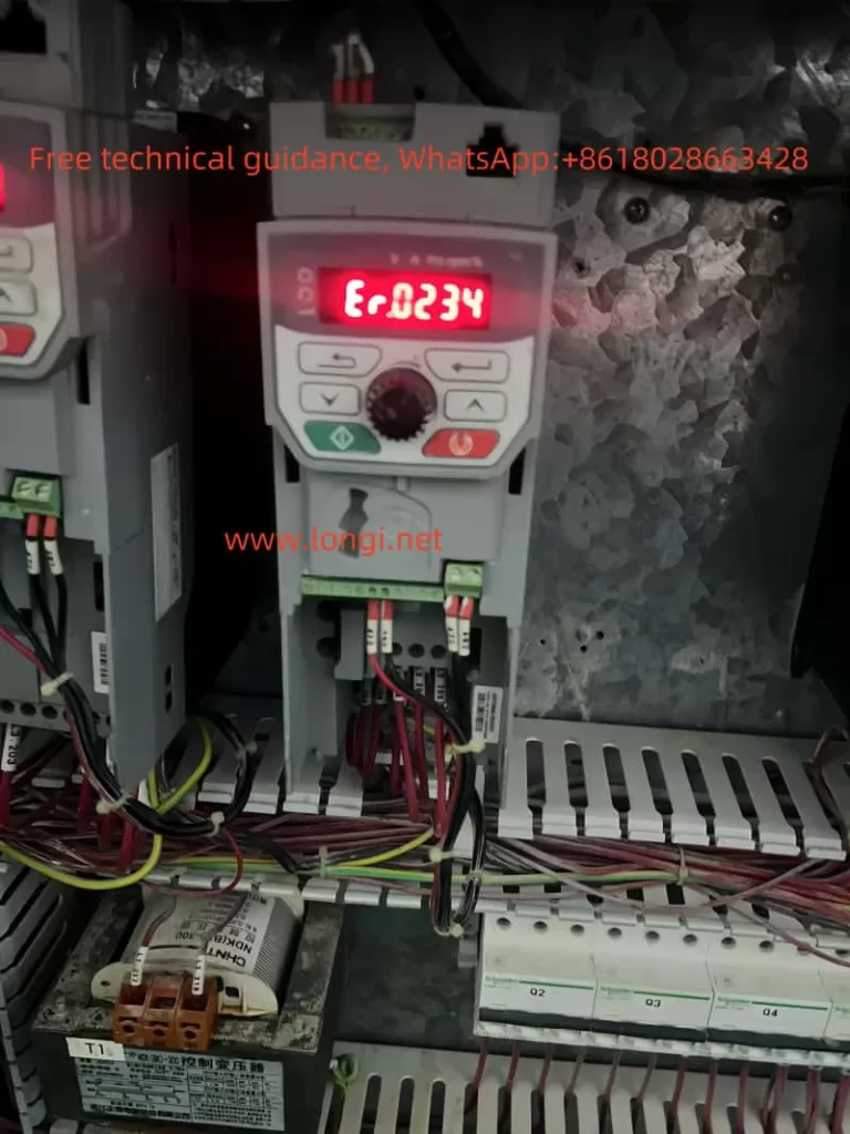
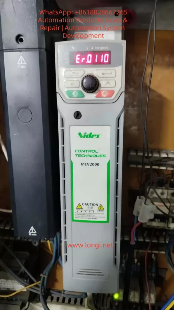
- Er.0110: Hardware fault (large-frame models)
Fault history can be accessed via Fn.00. Diagnosis should combine fault code review,现场 measurement, waveform observation, and power quality evaluation.
6. Detailed Analysis of Er.0110 Fault
Er.0110 (sub-code 1) indicates that internal operating parameters have exceeded safe limits and is limited to high-power MEV2000 models (typically above 75 kW). It is categorized as a hardware-related alarm.
Typical causes include:
- IGBT module failure or gate driver abnormality
- DC bus capacitor aging or imbalance
- EEPROM or control board malfunction
- Unstable or unbalanced input power supply
- Grounding defects and EMI interference
Diagnostic steps:
- Record operating conditions before trip
- Power off and discharge for 10 minutes
- Check DC bus connections and insulation resistance
- Reset and observe recurrence
- Measure DC bus ripple (<50 V p-p recommended)
- Inspect power modules and capacitor bank
Corrective measures:
- Replace faulty IGBT modules
- Renew aging electrolytic capacitors
- Upgrade firmware
- Install input reactors or harmonic filters
- Improve grounding and cabinet ventilation
Field experience shows that more than 70% of Er.0110 events are linked to external power quality problems rather than internal device defects.
7. Maintenance Strategy and Case Studies
Maintenance includes both preventive and corrective actions.
Preventive measures:
- Monthly cleaning of cooling fans and heat sinks
- Quarterly insulation and grounding inspection
- Annual auto-tuning and firmware updates
Corrective maintenance tools include multimeters, oscilloscopes, thermal cameras, and insulation testers.
Typical cases:
- Textile plant: Er.0110 caused by phase imbalance
- Pump station: capacitor degradation
- Conveyor system: moisture ingress on control board
Establishing spare part inventory and predictive monitoring through Modbus data collection significantly reduces downtime.
8. Maintenance and Upgrade Recommendations
- Replace cooling fans periodically
- Back up parameters using SD card modules
- Maintain cabinet temperature below 40 °C
- Implement LOTO safety procedures
- Consider upgrading to newer Unidrive M200 series platforms for Ethernet and advanced diagnostics
Regular maintenance can extend service life beyond ten years and reduce unexpected shutdowns.
9. Conclusion
The MEV2000 inverter remains a reliable industrial platform, but hardware faults such as Er.0110 require systematic diagnosis and professional maintenance. By understanding internal principles, ensuring proper installation, and implementing preventive maintenance, users can significantly improve system stability and service continuity.