
Introduction
The Fanuc CNC (Computer Numerical Control) system is a core component in modern manufacturing, driving precise machining across industries from aerospace to automotive. These systems, such as the Series 0i-MD, rely on precision servo amplifiers, spindle modules, and control units to ensure high-speed, accurate operation. However, faults such as alarm codes SYS_ALM455 (indicating fan motor stop and system shutdown) and SPM 24 (serial data error) can disrupt production, leading to costly downtime. Based on real-world diagnostics, these alarms often relate to each other, with the failure of a DC bus connector exacerbating the issue.
This article offers a comprehensive technical exploration of these alarms in Fanuc systems, especially focusing on the βiSVSP amplifier series (e.g., model A06B-6164-H343). Based on the Fanuc maintenance manual and troubleshooting guides, we detail the causes, diagnostic methods, repair procedures, and preventive measures. The goal is to provide engineers and technicians with actionable insights to minimize faults and extend system lifespan, following a structured approach from symptom recognition to root cause analysis, ensuring efficient repairs and preventing recurrence.
1. Overview of the Fanuc CNC System
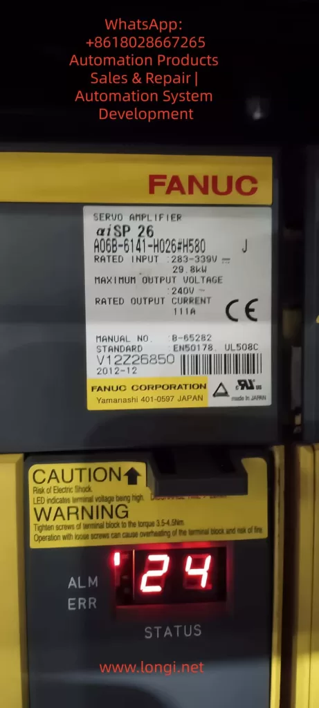
The Fanuc CNC architecture includes key components: the control unit (e.g., Series 0i-MD), servo amplifiers for axis control, spindle amplifiers (SPM) for rotation operations, and power supply modules (PSM). The βiSVSP series integrates the servo and spindle amplifiers into a compact unit, supporting multi-axis operation with high voltage capabilities up to 400V. For example, the A06B-6164-H343 model handles 40/40/80A servo current and 15kW spindle output, with a rated input of 200-240V AC at 50/60Hz.
Critical to the system’s reliability is the cooling mechanism, such as external or internal fans on the amplifier heat sinks, which dissipate heat from power transistors to prevent thermal shutdowns. Serial communication links the CNC controller to amplifiers via optical or electrical cables, ensuring synchronized data transmission of commands and feedback. Failures in these links or power distribution—such as through DC bus connectors (e.g., CX1A/B interface)—can cascade into alarms.
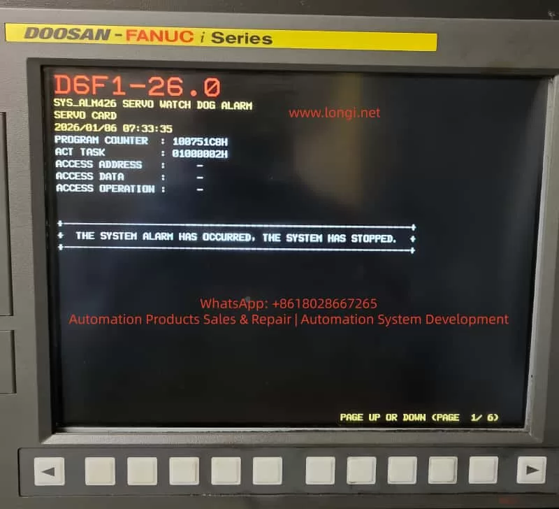
Understanding system interconnects is crucial: the DC bus links share power between modules, so loose connectors may underpower the fan or interrupt serial data, triggering SYS_ALM455 and SPM 24. Alarm logs with program counters (e.g., 10018B30H) and access addresses (e.g., 0100000AH) provide diagnostic clues, with timestamps (e.g., 2026/01/11 19:47:41) used for event correlation.
2. Alarm Code Analysis
SYS_ALM455: Fan Motor Stop and Shutdown
SYS_ALM455 indicates a cooling fan failure, prompting an immediate system shutdown to prevent damage from overheating of the amplifiers or motors. In the Fanuc Series 0i-MD, this alarm appears as “SYS_ALM455 FAN MOTOR STOP AND SHUTDOWN,” typically accompanied by a red LED on the amplifier.
Causes:
- Fan Hardware Failure: Motor burnout, bearing seizure, or blockage from accumulated dust. Fans in the βiSVSP units (typically 24V DC, 40mm in size) are prone to wear after 20,000-50,000 hours of operation.
- Power Issues: Fan circuit under-voltage due to DC bus fluctuations. Faulty main bus connectors (e.g., loose copper bars or oxidized pins) can drop the voltage below 22.8V DC, causing the fan to stop.
- Environmental Factors: High ambient temperatures (>40°C) or poor ventilation increase thermal load, accelerating failure. Electromagnetic interference (EMI) from nearby motors can also disrupt fan control signals.
- Software/Parameter Errors: Misconfigured parameters (e.g., No. 7310 for axis sequence) or checksum errors in the servo software, though rare in fan-specific alarms.
Diagnosis:
- Visual Inspection: Check the amplifier LED (e.g., red ALM/ERR indicates a fault). Verify fan rotation by powering up the cabinet.
- Voltage Measurement: Use a multimeter to measure voltage at the fan terminals; expect a stable 24V DC. Probe the DC bus (nominal 300V) for voltage drops.
- Log Analysis: Review CNC diagnostics (Nos. 400-499) for serial status and temperature readings. Use an oscilloscope to check for EMI on cables.
- Isolation Test: Disconnect the fan and test it independently. If it doesn’t rotate, the resistance between wires should be infinite.
If the alarm persists after power cycling, suspect an interconnect issue, such as a DC bus fault.
SPM 24: Serial Data Error
SPM 24 indicates a serial communication error between the CNC controller and the spindle amplifier module, shown as “24” on the SPM LED. It indicates data corruption or interruption, typically requiring a power cycle to reset.
Causes:
- Communication Interruption: Noise on the serial cable (e.g., optical fibers or CX3/CX38 interface) from EMI, exceeding the maximum cable length (per B-65282EN manual), or poor grounding.
- Power-Related Failures: CNC power loss during operation causing under-voltage on the SPM control PCB. Issues with main bus plugs—loose, damaged pins, or arcing—lead to unstable voltage, causing data parity errors.
- Hardware Defects: Faulty SPM PCB, transistor modules, or feedback signals. In βiSVSP, this correlates with DC bus undervoltage alarms (e.g., Alarm 5: Low DC Voltage).
- Cascading Effect: Often a secondary consequence of SYS_ALM455. The shutdown triggered by the fan failure disrupts power, resulting in SPM 24 as a “normal” response, but a persistent issue signals deeper problems.
Diagnosis logs may show “Serial Transfer Data Error,” with DGN No. 471 detailing spindle speed ratios or feedback mismatches.
Diagnosis:
- Cable Inspection: Check for damage on the serial link. Test continuity and shielding. Use a logic analyzer to measure signal integrity.
- Power Verification: Confirm AC input (200-240V) and DC bus (300V). Voltage fluctuations point to bus connector issues.
- Parameter Review: Check Nos. 400-499 for communication status. Reset if noise is suspected.
- LED Interpretation: SPM shows “-24” or “0 24” indicating specific sub-errors (e.g., cable fault vs. PCB issue).
3. Interlinking Alarms and DC Bus Issues
SYS_ALM455 and SPM 24 often occur together because they share a dependence on the DC bus. The main bus connector (copper bars or CX1 interface) distributes power; failures here lead to a cascade of alarms:
- Voltage drops cause fan stoppage (SYS_ALM455).
- Instability damages serial data (SPM 24).
In diagnostics, a loose connector manifests as intermittent alarms, exacerbated by vibration.
4. Fault Diagnosis Methodology
Effective diagnosis follows a logical, layered approach: symptom recording, isolation, and verification.
1. Initial Assessment:
- Record alarm timestamps, program counters, and access data on the CNC screen.
- Check the amplifier LED: red ALM indicates an error, blank display indicates a power failure.
- Use Fanuc’s teaching pendant or MDI panel to access parameters.
2. Tools and Techniques:
- Multimeter/Oscilloscope: For voltage, resistance, and waveform analysis.
- Thermal Imaging: Detect hotspots on amplifiers or connectors.
- Diagnostic Software: Fanuc’s PMC ladder logic viewer for signal tracking.
- Isolation: Swap modules (e.g., test the fan on a separate power supply) to pinpoint the fault.
3. Step-by-Step Protocol:
- Power Cycle: Reset alarms; if persistent, continue.
- Environmental Scan: Measure temperature/humidity; clean dust.
- Component Testing: Fan (rotation test), cables (continuity), connectors (visual/torque checks).
- Advanced: Monitor DGN parameters during operation to detect transient errors.
For βiSVSP, refer to the wiring diagram in B-65322. Document findings to identify patterns.
5. Repair Procedures
Repairs must prioritize safety: isolate power, use ESD protection, and follow OEM specifications.
For SYS_ALM455:
- Fan Replacement: Locate fan on the amplifier heat sink (rear/top). Disconnect, remove (screws/clips), and install a new fan (e.g., A06B-6134-K002). Test rotation.
- Cleaning: Use compressed air on the heat sink; avoid solvents on electronics.
- Power Repair: If voltage is low, reset the DC bus plug; clean oxidation with isopropyl alcohol. Torque to specification (e.g., 2-3 Nm).
- Verification: Power on, monitor for 30 minutes, and check diagnostics to clear.
For SPM 24:
- Cable Repair: Replace faulty serial cables; ensure proper shielding/grounding.
- PCB Replacement: If the PCB is suspected, replace the SPM control board (A20B-1009-0650 series).
- Bus Connector Repair: Discharge the system, remove the plug, and check the pins. Clean/replace if damaged; reconnect securely.
- Reset Sequence: Power down CNC and amplifier. Wait 5 minutes. Power on the amplifier first, then CNC.
Integrated Fix for Linked Alarms:
- Address the root cause (e.g., bus plug): disconnect, test resistance (<1Ω), and reassemble.
- After repairs: run spindle test (M03 S1000) and axis jog; monitor temperatures.
If the alarm recurs, escalate to Fanuc Service for PCB analysis.
Total repair time: 1-4 hours, depending on access.
6. Preventive Maintenance Best Practices
Proactive maintenance can reduce alarm frequency by 70-80%, based on industry benchmarks.
Daily/Weekly Routine:
- Visual Inspection: Check fans, cables, and connectors for wear.
- Cleaning: Remove dust from the cabinet; use intake filters.
- Monitoring: Check CNC logs for temperature (e.g., spindle load table).
Monthly/Quarterly:
- Voltage Audit: Measure input/output; calibrate if deviation >5%.
- Fan Service: Lubricate bearings; replace every 2 years.
- Cable Integrity: Torque check for bus plugs; validate EMI shielding.
Annual Overhaul:
- Comprehensive Diagnostics: Use Fanuc tools for parameter backup, firmware updates.
- Component Replacement: Batteries, fuses (e.g., F3 in PSM).
- Training: Ensure operators follow the power-up sequence (amplifier before CNC).
- Checklists: Daily (cleaning), 500 hours (check), 2000 hours (overhaul). Fanuc’s lifetime support and refurbished parts programs help control costs. Grounding to Class C standards prevents noise-induced errors.
7. Case Study: Resolving Interlinking Alarms in a Production Environment
In a recent scenario involving Fanuc Series 0i-MD and βiSVSP amplifiers, SYS_ALM455 and SPM 24 appeared simultaneously on 2026/01/11 at 19:47:41. Initial checks showed no fan rotation, with the DC bus voltage at 250V (below the nominal 300V). Diagnostics traced the fault to a loose main bus plug, causing undervoltage.
Fix: The system was powered off, and after cleaning, the plug was reset. The fan was independently tested (rotating at 24V). After repairs, alarms cleared, and spindle tests confirmed stable operation. Prevention: Added monthly torque checks and EMI filters. Downtime: 2 hours; prevented recurrence through planned maintenance.
This case highlights the value of comprehensive diagnostics, consistent with Fanuc’s B-65285EN manual recommendations.
Conclusion
SYS_ALM455 and SPM 24 showcase how interconnected Fanuc CNC components can lead to cascading faults, often stemming from power distribution issues like DC bus connectors. By mastering diagnostics (logs, tools), repairs (step-by-step), and prevention (routines), technicians can achieve >99% uptime. Always consult Fanuc manuals (e.g., B-65322, B-65282EN) and leverage OEM support for complex issues. Implementing these strategies not only resolves immediate problems but fosters long-term system resilience and optimized manufacturing efficiency.