
1. Introduction: Why the JOG Function Matters
In industrial automation commissioning and maintenance, the JOG (inching) function is one of the most fundamental and frequently used operations in servo systems. It allows technicians to move the motor at low speed and short stroke, mainly for direction checking, mechanical zero adjustment, load inspection, and fault diagnosis.
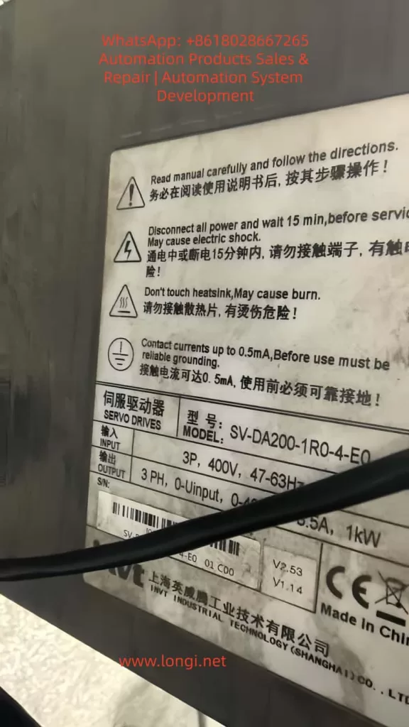
For the INVT SV-DA200 series servo drives (such as SV-DA200-1R0-4-E0, 3-phase 400V, 1kW), loss of JOG functionality often causes commissioning delays, maintenance inefficiency, and even production downtime.
This article systematically explains the core causes of JOG failure and provides a step-by-step troubleshooting workflow for automation engineers and maintenance teams.
2. Basic Conditions for JOG Operation
JOG function only works when the following logic chain is complete:
No alarm → Servo enabled → Correct mode → Parameters enabled → Hardware normal
- ALM LED OFF
- SERVO ON LED ON
- Correct operation mode selected
- JOG enabled and speed set
- Encoder, power supply, and motor normal
3. Step-by-Step Troubleshooting Guide
Step 1: Check Alarm Status
If the ALM indicator is ON, the servo drive is locked and JOG is disabled.
Common alarms include:
- E001 – Overcurrent
- E004 – Encoder error
- E006 – Overvoltage
- E010 – Undervoltage
Check the panel display or parameter Pr0.01.
Step 2: Check Servo Enable Signal
The SERVO ON LED must be ON.
- CN1: SON → +24V, SG → 0V
- Voltage between SON and SG should be about 24V
PLC output logic (NPN/PNP) must match wiring.
Step 3: Check Operation Mode and Parameters
Operation Mode (Pr0.00):
- 0 = Panel
- 1 = External terminal
- 2 = Communication
Critical JOG parameters:
- Pr0.05 = 1 (Enable JOG)
- Pr0.10 > 0 (JOG speed)
- Pr0.11 / Pr0.12 reasonable acceleration
- Pr0.06 JOG direction
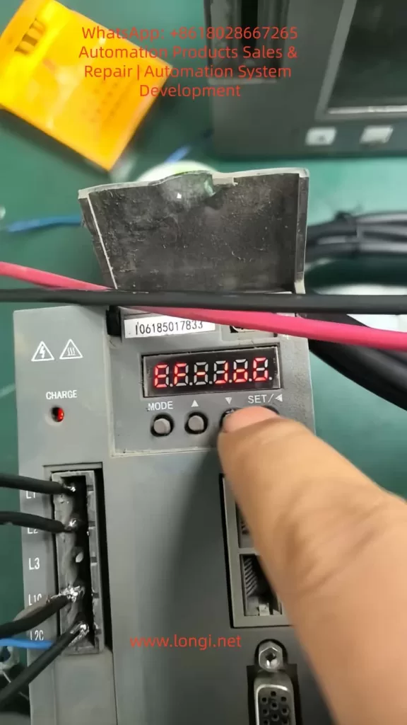
Step 4: Correct Panel Operation
Press MODE → select JOG → press ↑ or ↓.
Common errors: staying in parameter mode, speed set too low, parameters not saved.
Step 5: Wiring and Hardware Check
- Power: 3-phase 400V balanced
- Encoder: differential signals, shield grounded
- Motor: free shaft rotation, balanced phase resistance
Step 6: Special Scenarios
- Communication control: Modbus/EtherCAT JOG commands required
- Factory reset: Pr9.00 = 1
4. Preventive Maintenance
- Backup parameters
- Weekly terminal inspection
- Encoder grounding
- Alarm monitoring
- Operator training
5. Golden Diagnostic Logic
Alarm → Enable → Mode → Parameters → Operation → Wiring → Hardware
6. JOG Parameter Table
(参数表保持不变,适用于 INVT SV-DA200)
7. Conclusion
Most INVT SV-DA200 JOG failures are not hardware damage, but logical protection or parameter misconfiguration. Systematic diagnosis is far more effective than blind testing.