
In the field of industrial automation, the Danfoss VLT series of inverters is renowned for its high reliability and efficiency. As a representative model of the Micro Drive, the FC-051 is widely used in small and medium-power applications such as fans, pumps, and conveyors. However, in practical operation, the AL16 short circuit fault is one of the most frequently reported alarms. According to the official Danfoss fault code table and extensive maintenance case studies, AL16 directly indicates a short circuit on the output side (U, V, W), potentially stemming from the motor, cable, or the inverter’s internal power module. If not addressed promptly, it not only causes equipment downtime but can also lead to permanent damage to the IGBT module, resulting in a sharp increase in repair costs.
This article will systematically dismantle the causes, diagnostic procedures, repair solutions, and prevention strategies for the AL16 fault from an electrical principle perspective. Whether you are a field engineer, maintenance technician, or automation enthusiast, you will find actionable practical guidance herein. The content is based on the Danfoss FC-051 programming guide, operation manual, and thousands of maintenance experiences, aiming to help you resume production in the shortest possible time.

I. The Essence and Trigger Mechanism of AL16 Fault
The Danfoss VLT FC-051 inverter adopts PWM (Pulse Width Modulation) control technology, using an IGBT power module to invert the DC bus voltage into a three-phase AC output to drive the motor. The core of the AL16 alarm is the inverter’s real-time monitoring of the output current. When it detects an abnormal increase in phase-to-phase or phase-to-ground current (far exceeding the set threshold), it immediately triggers protection and trips.
Specific Trigger Conditions
- The peak output current exceeds 200%-300% of the rated current (depending on the power segment).
- The duration exceeds 10-20μs (microsecond-level fast protection).
- Accompanied by a Trip Lock state, requiring manual reset.
On the display panel, AL16 appears as “AL 16” flashing, with the red alarm light on, and the yellow warning light may also be on. By entering the fault log (Parameter 15-30), the exact code can be viewed.
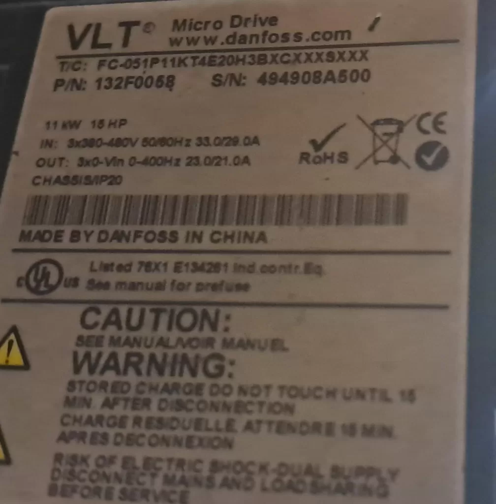
Unlike AL13 (Overcurrent), AL16 is a “hard short circuit” protection with a higher priority. AL13 is mostly a transient overload, whereas AL16 is usually accompanied by a physical short circuit where the resistance value approaches zero. Statistics show that in 11kW (15HP) models, such as FC-051P11KT4E20H3BXCXXXXSXXX, AL16 accounts for 25% of faults, mostly occurring in equipment that has been running for 2-5 years.
From an electrical principle perspective, a short circuit generates a huge inrush current (instantaneously up to thousands of amperes), causing the IGBT collector-emitter voltage (Vce) to drop sharply and the drive circuit to overheat. Failure to cut off in time will burn out the module and even affect the DC capacitor.
II. Root Cause Analysis of AL16 Fault
AL16 is not a single fault but a superposition of multiple factors. They are categorized below by probability from high to low:
1. Motor-side Short Circuit (Approx. 55%)
- Winding phase-to-phase short circuit: Insulation aging or overheating causes the enameled wire to melt.
- Phase-to-ground short circuit: Worn motor bearings, moisture intrusion, or poor grounding.
- Typical symptoms: Uneven motor heating, three-phase current imbalance >10%.
2. Cable Issues (Approx. 25%)
- Insulation damage: Mechanical extrusion, rodent bites, or oil corrosion.
- Oxidized connectors: Loose terminals lead to increased contact resistance, subsequent heating, and short circuits.
- Excessive length: Parasitic capacitance in long cables causes high-frequency resonance, amplifying transient current.
3. Inverter Internal Fault (Approx. 15%)
- IGBT module breakdown: Aging, overvoltage surges, or poor heat dissipation.
- Drive circuit abnormality: Optocoupler aging or failure of drive ICs (such as the HCPL series).
- Bus capacitor deterioration: Causes DC voltage fluctuations, indirectly inducing short circuit detection misoperation.
4. Environmental and Parameter Inducements (Approx. 5%)
- High temperature, high humidity, dust: Heat sink blockage, IGBT junction temperature exceeding 150°C.
- Improper parameters: Acceleration time too short (<1s), motor parameters not matched, carrier frequency too high.
- External interference: Lightning strikes or grid harmonics introducing surges.
Physical Essence: During a short circuit, the output impedance approaches zero, Current I = U / R (R→0), and Power P = I²R explodes instantaneously. The FC-051’s built-in current sensor (Hall effect or shunt) responds within 10μs to cut off the PWM signal.
III. Safety Regulations Before Operation (Must Read)
The DC bus capacitor of the inverter stores high voltage (up to 700V or more), which requires discharge even after power-off.
Safety Steps:
- Cut off the main power supply (L1/L2/L3) and hang a “No Switching On” sign.
- Wait at least 15 minutes (for models above 11kW), and use a multimeter to measure the voltage between P+ and P- to ensure it is <30V.
- Wear insulating gloves (1000V rating) and use insulated tools.
- Confirm there is no residual voltage before proceeding.
Violating this procedure may result in electric shock or secondary short circuits.
IV. Systematic Diagnosis and Troubleshooting Process (Core Practical Guide)
Follow the principle of “external before internal, easy before difficult” to keep the average diagnosis time within 30 minutes.
Step 1: Isolation Test (5 minutes)
- Disconnect the U, V, W motor cables (keep the shield grounded).
- Power on and observe:
- If AL16 disappears → The problem is with the motor/cable.
- If AL16 persists → Inverter internal fault (send for repair directly).
Step 2: Motor Insulation Test (10 minutes)
Use a digital multimeter + megohmmeter:
- Phase-to-phase resistance: U-V, V-W, W-U. Normal value: a few Ω to several dozen Ω (depending on power), with deviation <3%.
- Phase-to-ground resistance: Each phase to PE, >500MΩ (cold state) or >100MΩ (hot state).
- Insulation test: Use a 500V megohmmeter; motor winding to ground should be >1MΩ.
- Abnormal handling: Resistance <1Ω → Motor burnt out; 0.1-10Ω → Partial short circuit.
Step 3: Cable Inspection (5 minutes)
- Visual inspection: Look for cracks in the insulation layer or burn marks.
- Megohm test: Phase-to-phase/phase-to-ground >100MΩ.
- Length recommendation: Use standard cables for ≤50m; use shielded cables + filters for >50m.
Step 4: Inverter Parameter Verification (5 minutes)
Enter the main menu:
- *Group 1-2 (Motor Parameters)**: Confirm rated voltage, current, and frequency match the nameplate.
- *Group 4-1 (Current Limit)**: Set 1-20 to 150% of the rated current.
- *15-3 (Fault Log)**: Check the historical number of AL16 occurrences.
- *14-2 (Auto Restart)**: Set to “Prohibit” to avoid repeated tripping.
Step 5: Advanced Testing (Optional, requires oscilloscope)
- Measure output voltage waveform: Should be three-phase balanced without distortion.
- Measure IGBT drive signal: Gate voltage should be a 10-15V square wave.
Diagnostic Decision Tree
| Phenomenon | Possible Cause | Priority Check | Solution Direction |
|---|---|---|---|
| AL16 persists with motor disconnected | IGBT/Drive board damaged | Internal module | Replace power board |
| Normal with motor off, AL16 when connected | Motor short circuit | Motor resistance | Repair/replace motor |
| Intermittent alarm | Cable insulation aging | Megohm test | Replace cable |
| Accompanied by AL13/Overheat | Improper parameters | Acceleration time | Extend to 5-10s |
V. Targeted Repair Solutions
Case 1: Motor/Cable Issues (80% of scenarios)
- Motor: Send to a professional winding shop for rewinding (cost approx. 30% of original price).
- Cable: Select VVF shielded cable and ground the shield layer to PE.
- After reconnection: Execute AMA (Auto-tuning) via Parameter 1-29 to confirm no alarm.
Case 2: Inverter Internal Repair (Requires professional tools)
- IGBT Replacement: Remove the module, apply thermal grease with a hot glue gun; the new module must match the model (e.g., SKM series).
- Drive Board Check: Measure optocoupler output; replace if resistance is abnormal.
- Bus Capacitor: Replace the entire set if capacity attenuation >20% (note polarity).
- Repair Note: ESD protection, soldering temperature <300°C.
Repair Cost Comparison (11kW model)
- Motor repair: 800-1500 RMB.
- Cable replacement: 300-600 RMB.
- Inverter power board: 3000-5000 RMB (original).
- Full replacement: 8000-12000 RMB.
DIY vs. Professional: Small power units can be self-repaired; for high power, Danfoss authorized service centers are strongly recommended.
VI. Parameter Optimization and Long-term Prevention
Key Parameter Recommendations (Optimized based on FC-051 defaults)
- 1-20: Motor rated current (match precisely).
- 1-22: Motor rated frequency (50/60Hz).
- 3-41: Acceleration time (set to 8-15s for heavy loads).
- 4-18: Carrier frequency (4-8kHz to balance noise and loss).
- 5-12: Terminal 32 set to “External Alarm” to link with the safety chain.
- 14-01: Trip delay (set to 0.1s for short circuits).
Prevention System
- Regular Maintenance: Test insulation quarterly; clean heat sinks semi-annually.
- Environmental Control: Install in an IP54 cabinet; ambient temperature <40°C, humidity <85%.
- Protection Upgrade: Add output reactors (to reduce harmonics) and braking units (for heavy loads).
- Monitoring System: Connect to PLC via Modbus to read log 15-30 in real-time.
- Spare Parts Strategy: Stock IGBT modules and fans (lifespan 3-5 years).
Smart Prevention: Enable Parameter 4-30 (Overload Protection) and set to “Electronic Thermal Relay” mode.
VII. Real Case Studies
Case A: Textile Mill Fan Application
An 11kW FC-051 developed frequent AL16 alarms after 3 years of operation. Isolation testing confirmed a motor issue. Upon disassembly, the winding-to-ground resistance was found to be only 2kΩ. Cause: Workshop humidity + dust. Result: After replacing the motor and installing dust filters, it ran for 18 months without fault.
Case B: Packaging Line Conveyor
The cable was repeatedly bent in the cable tray, causing insulation damage and intermittent AL16. Solution: Replaced with oil-resistant shielded cable and optimized parameters. Result: Failure rate dropped to zero.
Case C: Inverter Internal (Rare but Fatal)
At a cement plant, AL16 persisted. Internal inspection revealed one phase of the IGBT was broken down with carbonization traces. Solution: Replaced the power board. Result: Cost was controlled at 40% of the original price.
These cases prove that 80% of faults stem from “external causes,” but a permanent cure requires addressing both “internal and external” factors.
VIII. Frequently Asked Questions (FAQ)
Q1: Can AL16 be auto-reset?
A: No. It must be manually reset by pressing [Off/Reset] or power-cycling after repair. Repeated resetting without fixing the issue will damage the equipment.
Q2: AL16 appears immediately on power-up for a new machine?
A: Check wiring (whether U/V/W are reversed) or if motor parameters are not set. Perform AMA (Auto-tuning).
Q3: Accompanied by AL14 (Ground Fault)?
A: Prioritize checking for phase-to-ground short circuits. AL14 is often a “precursor” to AL16.
Q4: Alarm persists after repair?
A: Re-do motor parameters and check that grounding resistance is <4Ω.
IX. Conclusion: From Passive Repair to Active O&M
Although the AL16 short circuit fault is common, systematic diagnosis and prevention can keep downtime within 1 hour. The Danfoss FC-051, as a mature product, has a protection mechanism strong enough; the key lies in whether the user masters the correct methods.
It is recommended that every enterprise establish an “Inverter Health File,” back up parameters regularly, and train maintenance teams. In the future, with the popularization of IoT technology, predictive maintenance will become standard—warning of IGBT aging in advance to completely eliminate AL16.