
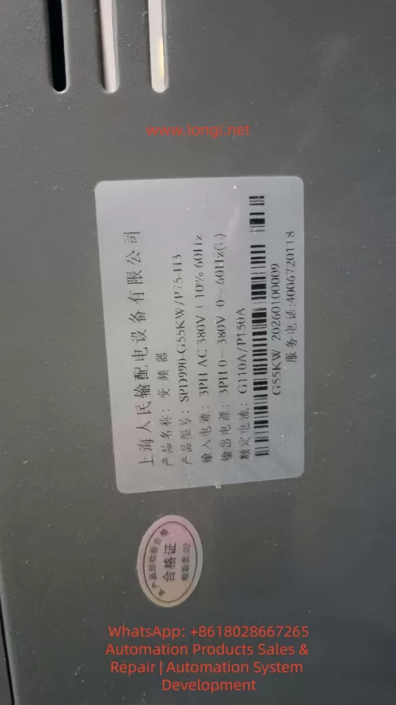
The SPD990 series high-performance current vector inverters from Shanghai People’s Electric Appliance integrate four core control modes: ordinary V/F control, advanced V/F control, separated V/F control, and open-loop current vector control. With features such as wide voltage adaptability, high-precision speed regulation, and comprehensive overload/overvoltage/overheating protection functions, these inverters are widely compatible with three-phase AC asynchronous motors. They are extensively applied in industrial automation scenarios, including fans, pumps, conveyor belts, machine tools, textile machinery, and constant-pressure water supply systems, serving as the core industrial control equipment for achieving energy-saving speed regulation and stable motor operation in industrial settings.
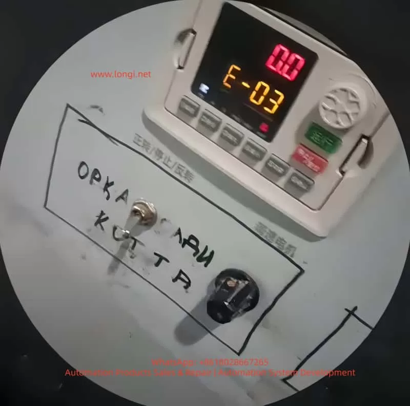
During long-term continuous operation, inverter faults are the primary cause of production line shutdowns and equipment damage. Among them, the E-03 overcurrent fault during constant-speed operation is one of the most frequently triggered, most widely impactful, and most clearly traceable typical faults in the SPD990 inverter. Upon triggering this fault, the inverter immediately blocks PWM power output, cuts off power supply to the motor, and displays the E-03 code with a flashing operation panel and a constantly lit ALM fault indicator. In mild cases, it causes production interruptions, while in severe cases, it can lead to irreversible hardware damage, such as motor winding burnout and inverter IGBT power module breakdown.
This article strictly adheres to the official user manual of the Shanghai People’s Electric Appliance SPD990 inverter and combines thousands of actual industrial field maintenance cases to provide an in-depth analysis of the official definition, triggering mechanism, and all-dimensional causes of the E-03 fault. It offers a full-process technical solution from safe shutdown, rapid troubleshooting, precise repair to long-term prevention. All content is practical technical know-how without redundant expressions, serving as a directly applicable fault handling guide for industrial control maintenance engineers, equipment repair personnel, and electrical technicians.
I. Official Definition and Core Triggering Mechanism of the SPD990 Inverter E-03 Fault
According to Chapter 9 “Fault Diagnosis and Countermeasures” in the SPD990 inverter user manual, the E-03 fault, fully named “Overcurrent during Constant-Speed Operation,” is a safety mechanism triggered by the DSP controller in milliseconds when the internal current detection circuit detects that the output-side three-phase current exceeds the rated current limit protection threshold during the stable constant-speed operation phase after the inverter drives the motor through the acceleration process and reaches the set frequency.
1. Officially Stated Core Causes of the Fault
The manual explicitly identifies three direct causes of the E-03 fault:
- Sudden or abnormal load changes: Sudden increases in motor load during constant-speed operation, mechanical transmission mechanism jamming, or load-end stalling.
- Undersized inverter power: The rated output current of the inverter is less than the rated operating current of the motor, leading to long-term overload operation and triggering protection.
- Implicit associated causes: Abnormal fluctuations in grid voltage, hardware faults in the motor itself, and unreasonable control parameter settings.
2. Core Working Principle of Overcurrent Protection
The SPD990 inverter employs full-process current closed-loop control. High-precision Hall current sensors are built in to sample the U, V, and W three-phase output currents in real time, converting the current signals into voltage signals and transmitting them to the main control board. During constant-speed operation, with stable motor speed and constant output frequency, the output current should remain within the rated range under normal load conditions. When the output current exceeds 160% of the rated current for G-type machines or 120% of the rated current for P-type machines (set by the F9.06 parameter), the main control board immediately determines it as an overcurrent fault, cuts off the drive signals to the IGBT power modules, and outputs a fault alarm, providing dual protection for the inverter power devices and motor windings.
Key distinguishing points: Overcurrent faults in SPD990 inverters are triggered in three scenarios. The E-03 fault is triggered only during the stable constant-speed phase, while overcurrent during acceleration triggers the E-01 fault, and overcurrent during deceleration triggers the E-02 fault. The triggering phases are different, and the troubleshooting logic is completely distinct, which is the core premise for locating the E-03 fault.
II. Comprehensive and Precise Troubleshooting of All-Dimensional Causes of the SPD990 Inverter E-03 Fault
Based on the actual operating environment in industrial fields, the causes of the E-03 fault can be categorized into four main types: load-side abnormalities, inverter body faults, incorrect parameter settings, and electrical wiring and environmental interference. Each type of cause has corresponding clear fault characteristics and troubleshooting directions, covering 100% of fault scenarios.
(I) Load-Side Abnormalities: The Primary Cause of the E-03 Fault (Accounting for over 70%)
The load is the direct driving object of the inverter, and the stability of the load during constant-speed operation directly determines the magnitude of the output current. Load abnormalities are the core reason for triggering the E-03 fault, with specific subdivisions as follows:
1. Sudden Load Changes and Mechanical Jamming
- Fluid load backpressure: Blockages in pipes, partially open valves, or scale buildup on filters in fans and pumps lead to a sudden increase in fluid resistance, doubling the motor load instantly.
- Transmission load jamming: Overweight material accumulation on conveyor belts and conveyors, broken gear teeth in reducers, belt slippage/breakage, or eccentric coupling prevent the motor’s output torque from being transmitted, causing a sudden change in load resistance.
- Processing load stalling: Stalling of workpieces in machine tools and textile machinery due to jamming, yarn winding, or mold sticking causes the motor to tend to stall, resulting in a sharp increase in current.
2. Hardware Faults in the Motor Itself
- Winding faults: Inter-turn short circuits, phase-to-phase short circuits, or ground short circuits in the stator windings reduce the motor’s equivalent resistance, causing the current to rise exponentially.
- Mechanical faults: Worn motor bearings, rotor rubbing, or stuck cooling fans significantly increase rotational resistance, leading to motor overload operation.
- Selection and operation faults: Long-term low-frequency operation (below 30 Hz) of ordinary motors results in poor heat dissipation, causing winding overheating and insulation degradation, and abnormal current.
- Overload in multi-motor parallel operation: When one inverter drives multiple asynchronous motors, if the total rated current of the motors exceeds 1.1 times the rated output current of the inverter, overload occurs during constant-speed operation.
(II) Inverter Body Faults: Overcurrent Caused by Hardware Abnormalities
Hardware damage in the inverter itself can lead to current detection inaccuracies or abnormal power output, triggering the E-03 fault. These are hardware-related faults with relatively high troubleshooting difficulty:
1. Incorrect Power and Model Selection
The SPD990 inverter is divided into G-type (for constant-torque loads) and P-type (for fan and pump square-torque loads), with significantly different overload capabilities. G-type machines support 110% long-term overload and 150%/5-second instantaneous overload, while P-type machines support only 105% long-term overload and 150%/1-second instantaneous overload. Using a P-type machine for constant-torque loads such as machine tools and cranes or selecting an inverter with a power rating one level lower than the motor will inevitably result in overload and overcurrent during constant-speed operation.
2. Current Detection Circuit Faults
Damage to Hall current sensors, drift in current sampling resistors, or abnormalities in the current signal processing circuit on the main control board can lead to inaccurate current detection values, either causing false E-03 alarms or triggering protection when the actual current exceeds the limit.
3. Power Module and Heat Dissipation Faults
Minor breakdowns in IGBT power modules or aging drive circuits can cause distortion in the output current waveform, increasing the effective value. Blocked air ducts due to dust accumulation, damaged cooling fans, or overheating of the heat sink (exceeding the 65°C threshold set by F9.14) in the inverter can indirectly trigger overcurrent protection (interlocked triggering of overheating and overcurrent).
4. Main Control Board Faults
Program disorders or aging components on the main control board can lead to misjudgment of the current protection threshold, triggering the E-03 fault irregularly.
(III) Incorrect Parameter Settings: Overcurrent Caused by Improper Software Configuration
The parameters of the SPD990 inverter are the core for controlling its operation. Mismatched parameters with the motor and load are common software causes of the E-03 fault:
1. Uncalibrated Motor Parameters
Failure to enter parameters such as F1.01 (rated power), F1.04 (rated voltage), and F1.05 (rated current) according to the motor nameplate or failure to perform F1.16 motor static/dynamic self-learning prevents the inverter from accurately matching the motor characteristics, resulting in uncontrolled output current during constant-speed operation.
2. Improper V/F Control Parameter Settings
Incorrect selection of the F3.00 V/F curve, excessively high F3.01 torque boost values leading to excessive low-frequency torque and overcurrent during constant-speed operation, and unreasonable setting of the F3.02 torque boost cutoff frequency further aggravate motor overload.
3. Incorrect Current Limit Protection Parameter Settings
Setting the F9.06 current limit level too low (G-type < 160%, P-type < 120%) can trigger overcurrent protection even during normal load operation. Improper setting of the F9.08 (acceleration current limit) and F9.09 (constant-speed current limit) coefficients fails to suppress current fluctuations.
4. Incorrect Control Mode Selection
Open-loop current vector control (F0.01 = 2) is highly sensitive to motor parameters. Control precision decreases and current fluctuations become excessive, triggering the E-03 fault if self-learning is not performed.
(IV) Electrical Wiring and Environmental Interference: Implicit Causes Often Overlooked
1. Output Wiring Faults
Short circuits between phases or to ground in the inverter’s U/V/W output lines, poor contact at wiring terminals, and failure to install output reactors for 380V series output lines exceeding 100 meters can lead to a sudden increase in output current due to high-order harmonics increasing leakage current.
2. Grid and Grounding Issues
Unbalanced three-phase grid voltages or voltage fluctuations exceeding ±10% can cause abnormal input voltages in the inverter, resulting in unbalanced output currents. Long grounding wires or shared grounding with high-power equipment can cause electromagnetic interference, leading to inaccurate current detection.
3. Environmental Interference
Electromagnetic interference from electric welding machines, high-power inverters, and contactors on-site, operation at temperatures exceeding 40°C without derating, and abnormal operation of inverter components can trigger overcurrent protection.
III. Step-by-Step Troubleshooting and Practical Solutions for the SPD990 Inverter E-03 Fault
For the E-03 fault, a 7-step step-by-step troubleshooting plan is formulated following the principles of starting with the easy and then the difficult, addressing mechanical issues before electrical ones, and dealing with software problems before hardware ones. Maintenance personnel can directly follow these steps for operation:
Step 1: Safe Shutdown and Power-Off Confirmation (Core Safety Operation)
Immediately press the STOP/RESET key to force a shutdown when the inverter triggers a fault. Do not perform maintenance with power on. Disconnect the input-side non-fuse breaker according to the manual’s safety requirements and wait for more than 10 minutes until the internal DC capacitors of the inverter are fully discharged (the charging indicator goes out) before proceeding with disassembly and wiring checks to avoid electric shock and arc injuries.
Step 2: Fault Status and Parameter Confirmation
Power on again without starting the motor and enter the d-group monitoring parameter interface of the inverter to check key operating data:
- d-05: Check the output current before the fault to confirm whether it exceeds the rated current of the inverter.
- d-33/d-34: Check the heat sink temperature to confirm whether it exceeds the 65°C overheating threshold.
- d-51: Confirm that the current fault type is E-03 to rule out interference from other faults.
- F0.00: Check whether the G/P model matches the load type.
Step 3: Load-Side Mechanical and Motor Troubleshooting (Prioritize Troubleshooting)
1. Mechanical Load Inspection
- Manual disk test: Disconnect the coupling between the motor and the load and manually rotate the motor shaft to check for jamming or excessive resistance.
- Load mechanism cleaning: Clean blockages in fan/pump pipes, remove foreign objects from conveyor belts, and repair reducer faults to ensure smooth operation of the transmission mechanism.
- Load matching verification: Confirm that the load is not overweight and that the valves of fans and pumps are fully open, with no risks of backpressure or stalling.
2. Motor Body Detection
- Insulation test: Use a 500V megohmmeter to measure the insulation resistance of the motor windings to ground, which should be ≥ 5MΩ. A lower value indicates damage to the winding insulation.
- Winding balance test: Measure the DC resistance of the three-phase windings. The difference in resistance values between the three phases should be ≤ 5%. Otherwise, there is a winding short circuit.
- Mechanical test: Check the motor bearings, fans, and rotors for wear or rubbing.
- Multi-motor parallel verification: Calculate the total rated current of the motors to ensure it is ≤ 1.1 times the rated output current of the inverter.
Step 4: Inverter Body Hardware Detection
1. Power and Model Review
Check the inverter model and motor power: G-type machines are suitable for constant-torque loads, and their power should match the motor. P-type machines are suitable for fan and pump loads, and their power can be one level lower. Replace with the corresponding model immediately if the selection is incorrect.
2. Heat Dissipation System Maintenance
Clean dust from the inverter air ducts and replace damaged cooling fans. Set the FE.08 fan control parameter to 1 (forced operation) to ensure that the heat sink temperature remains stable below 40°C.
3. Power Module and Detection Circuit Detection
Use a multimeter to measure the three-phase output of the IGBT module for short circuits or breakdowns.
Check the wiring of Hall sensors and the current sampling circuit on the main control board for looseness or damage.
Replace the power module or main control board directly or send them for repair if hardware damage is detected.
Step 5: Inverter Parameter Calibration and Optimization (Core of Software Repair)
1. Precise Motor Parameter Settings
Enter the F1 group motor parameters and input the following strictly according to the motor nameplate:
- F1.01 (motor rated power), F1.02 (rated frequency), F1.03 (rated speed), F1.04 (rated voltage), F1.05 (rated current).
Set F1.16 = 1 (static tuning) and perform parameter self-learning with the motor unloaded to obtain accurate motor characteristic parameters.
2. V/F and Control Parameter Optimization
- F0.01 control mode: Set to 0 (ordinary V/F control) when the load requirements are low to reduce control sensitivity.
- F3.00 V/F curve: Set to 4 (square curve) for fans and pumps and to 0 (linear curve) for constant-torque loads.
- F3.01 torque boost: Set to 0.0% (automatic boost) to avoid excessive manual boost causing overload.
- F9.06 current limit level: Set to 160% for G-type machines and 120% for P-type machines to restore the factory current limit values.
3. Protection Parameter Reset to Default
Set the F9.08 acceleration current limit coefficient and F9.09 constant-speed current limit to factory values and enable the automatic current limiting function.
Step 6: Electrical Wiring and Environmental Rectification
1. Output Wiring Rectification
Tighten the U/V/W wiring terminals to ensure no looseness or short circuits. Do not install capacitors or surge absorbers on the output side.
Install output AC reactors if the output lines exceed 100 meters to reduce harmonic leakage current.
Separate power lines from control lines in wiring, and use shielded control lines with single-end grounding.
2. Grounding and Grid Optimization
Use independent single-point grounding for the inverter’s grounding terminal, with a grounding wire length ≤ 2 meters. Avoid sharing grounding with electric welding machines and high-power motors.
Install input reactors and voltage stabilizers to stabilize the input voltage if the grid voltage fluctuations are large.
Step 7: No-Load and Loaded Trial Operation Verification
1. No-load trial operation
Disconnect the load, start the inverter, and operate at a constant speed for 10 minutes. Check that the output current is normal and no E-03 fault occurs.
2. Loaded trial operation
Connect the load, gradually increase the frequency, and operate at a constant speed for 30 minutes. Monitor that the output current is stable, indicating that the fault has been completely resolved.
IV. Typical Industrial Case Analysis of the SPD990 Inverter E-03 Fault
Case 1: E-03 Fault Caused by Blockage in a Fan Load
A SPD990-5.5KW/P-type inverter in a factory workshop drives a centrifugal fan and frequently reports the E-03 fault during operation. Troubleshooting revealed extremely high resistance when manually rotating the fan shaft. Upon disassembly, a large amount of debris was found blocking the fan’s air inlet, causing backpressure and overload. Solution: The debris was cleared, the fan bearings were lubricated, and the inverter restarted. The constant-speed operating current remained stable at the rated value, permanently eliminating the fault.
Case 2: E-03 Fault Caused by Unperformed Motor Parameter Self-Learning
A SPD990-7.5KW/G-type inverter on a production line frequently reported the E-03 fault during the constant-speed phase after replacing the motor. Troubleshooting revealed that the inverter had not entered the new motor’s nameplate parameters and had not performed motor self-learning, resulting in a mismatch between the control parameters and the motor. Solution: The new motor’s rated parameters were entered, static self-learning was performed, and the V/F curve was optimized, immediately eliminating the fault.
Case 3: E-03 Fault Caused by Incorrect Inverter Selection
A machine tool equipment used a SPD990-11KW/P-type inverter (for fan and pump loads) to drive a constant-torque machine tool spindle, frequently experiencing overcurrent during constant-speed operation. Troubleshooting revealed that the P-type machine had insufficient overload capacity and could not meet the high-torque requirements of the constant-torque load. Solution: The inverter was replaced with a G-type 11KW model to match the load characteristics, permanently resolving the fault.
V. Long-Term Prevention Measures for the SPD990 Inverter E-03 Fault
Regular Load Maintenance
Inspect the mechanical transmission mechanism weekly, remove foreign objects, lubricate bearings, and tighten connecting parts. Test the motor insulation and winding resistance monthly to ensure normal motor operation.
Standardized Model Selection and Parameter Settings
Select G/P-type machines strictly according to the load type, and ensure that the inverter power is ≥ the motor power. Enter the motor’s nameplate parameters and perform self-learning when powering on for the first time. Do not arbitrarily modify current limit and torque parameters.
Daily Inverter Inspection
Check the cooling fan and air duct temperature daily and clean dust. Test wiring terminals, grounding, and output lines monthly for looseness, short circuits, or aging.
Electrical Environment Optimization
Install input/output reactors to suppress grid harmonics and output leakage current. Standardize wiring and grounding to reduce electromagnetic interference. Control the ambient temperature within -10°C to 40°C and humidity ≤ 90%, and enforce heat dissipation in high-temperature environments.
Conclusion
The E-03 constant-speed overcurrent fault in the Shanghai People’s Electric Appliance SPD990 inverter is not caused by a single hardware or software issue but rather results from the combined effects of load, inverter, parameter, and environmental factors. Maintenance personnel only need to firmly grasp the core characteristic of being triggered only during the constant-speed phase and follow the troubleshooting logic of “starting with the easy and then the difficult, addressing mechanical issues before electrical ones, and dealing with software problems before hardware ones” to quickly locate the causes and accurately resolve the fault.
Meanwhile, by implementing preventive measures such as standardized model selection, parameter calibration, daily maintenance, and environmental optimization, the triggering probability of the E-03 fault can be fundamentally reduced, ensuring the long-term stable operation of the SPD990 inverter and motor system and providing reliable support for the continuous production of industrial automation production lines.
In actual maintenance, over 90% of E-03 faults can be resolved through simple operations such as load cleaning, motor parameter calibration, and wiring tightening. Only a few cases involving hardware damage require part replacement. Mastering the troubleshooting and repair methods in this article can significantly shorten fault handling time, reduce equipment repair costs, and improve the operational efficiency of industrial control equipment.