
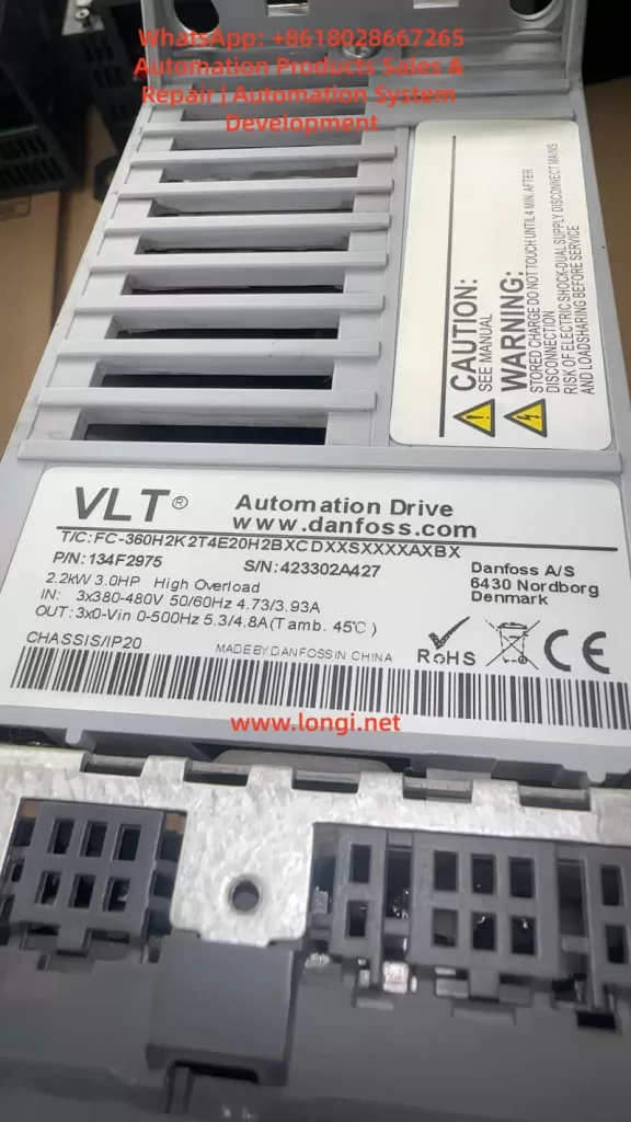
The Danfoss VLT Micro Drive FC-051 is a compact general-purpose inverter widely used in fans, pumps, conveyors, packaging machines, light industrial equipment, mixers, textile machines, and standard three-phase asynchronous motor speed control systems. Because of its compact structure, limited heat dissipation space, and frequent use in dusty electrical cabinets, the FC-051 may report temperature-related faults after long-term operation. One of the common alarms seen on site is AL29.
When a Danfoss FC-051 displays AL29, it usually indicates an overtemperature condition in the power section, power board, heatsink, or related temperature detection circuit. The drive stops output to protect the IGBT module, rectifier bridge, DC bus capacitors, and gate drive circuit. This alarm should not be treated as a simple parameter error. It is a thermal protection alarm, and the correct troubleshooting direction should focus on cooling, load current, cabinet ventilation, ambient temperature, fan condition, and the temperature feedback circuit.
- Meaning of AL29 on Danfoss FC-051
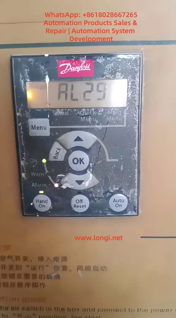
AL29 on the Danfoss FC-051 can generally be understood as a power board or heatsink overtemperature alarm. It means that the internal temperature of the drive has reached the protection threshold, or the temperature detection circuit has sent an abnormal high-temperature signal to the control board.
Inside the inverter, the main heat-generating components include the rectifier bridge, IGBT module, braking circuit, DC bus capacitors, switching power supply, power resistors, and high-current copper traces on the power board. Among these, the IGBT module and heatsink area are usually the most critical parts related to AL29.
During operation, the input AC power is rectified into DC bus voltage. The IGBT module then switches at high frequency to generate variable-frequency and variable-voltage three-phase output for the motor. The IGBT produces conduction loss and switching loss. The heavier the load and the higher the output current, the more heat the power module generates. If this heat cannot be removed quickly, the heatsink temperature rises. When the temperature reaches the trip point, the inverter stops output and displays AL29.
Therefore, AL29 is a protection result, not a single fixed component failure. It may be caused by real overheating due to poor cooling, a damaged cooling fan, excessive output current, overload, poor cabinet ventilation, high carrier frequency, or a faulty temperature detection circuit.
- Why the FC-051 Is Prone to AL29
The FC-051 is a compact inverter. Many machines install it in a small control cabinet to save space. Sometimes several drives are mounted close to each other, with insufficient clearance at the top and bottom. For small drives, users often underestimate the importance of airflow and heat dissipation.
In actual industrial environments, the control cabinet may also contain contactors, power supplies, PLCs, servo drives, braking resistors, transformers, and other heat-generating components. If the cabinet is closed, the filter is blocked, or the cabinet fan does not work properly, the internal cabinet temperature can be much higher than the workshop temperature.
For example, the workshop temperature may be 35°C, but the internal cabinet temperature may rise to 45°C or even higher. If the inverter is running near full load under such conditions, the thermal margin becomes very small. AL29 then becomes likely, especially during summer, continuous operation, or high-load operation.
The FC-051 is also commonly used on fans and pumps. After long-term use, these machines may develop mechanical problems such as bearing wear, blocked impellers, dirty fan blades, pipe blockage, excessive pressure, belt over-tension, or increased mechanical resistance. These issues increase motor current and make the inverter heat up. In many cases, the drive alarm is only the visible symptom, while the real cause is a mechanical load problem.
- Common Causes of AL29
3.1 Blocked cooling path and dusty heatsink
A very common cause of AL29 is dust blockage. If the front panel of the inverter is already covered with dust, the rear heatsink, bottom air inlet, top air outlet, and internal airflow path may also be dirty.
The inverter does not mainly dissipate heat through the front panel. The heat from the IGBT module is transferred to the heatsink through thermal grease and then removed by airflow. If the heatsink fins are blocked by dust, oil, cotton fiber, metal powder, or other contaminants, air cannot flow through the fins properly. Even if the load current is not excessive, the inverter may still trip on AL29 after running for some time.
In dusty environments, overtemperature alarms often become more frequent gradually. At first, the drive may trip only occasionally in summer. Later, it may trip after a few hours. Eventually, it may trip after only several minutes of operation. This pattern usually indicates worsening cooling conditions, fan aging, or heatsink contamination.
3.2 Cooling fan failure
Some FC-051 models or power ratings use a cooling fan. The fan must be checked carefully when troubleshooting AL29.
Fan faults include complete failure to rotate, slow rotation, difficult starting, intermittent stopping, bearing noise, vibration, dirty blades, or insufficient airflow. A fan may still rotate but provide very little airflow because of aging bearings or dust accumulation. This is why simply seeing the fan rotate is not enough. The actual airflow must also be checked.
The correct inspection method is to observe the fan during startup, listen for abnormal sound, feel the airflow at the air outlet, check the fan connector, and measure the fan supply voltage if necessary. If the fan is noisy, weak, unstable, or slow to start, it should be replaced.
3.3 Poor cabinet ventilation or high ambient temperature
Poor ventilation is one of the most common site-related causes. The drive may be installed too close to other components. The top outlet may be blocked by wiring ducts. The lower air inlet may be restricted by terminals or cables. Several drives may be mounted vertically, causing the upper drive to inhale hot air from the lower drive.
A control cabinet must have a clear airflow path. If there is no cabinet fan, if the filter cotton is blocked, or if the cabinet is located near a heat source, the internal temperature will rise. Under this condition, AL29 is not caused by a single defective part but by poor thermal design of the cabinet.
The cabinet temperature, inverter inlet temperature, outlet temperature, and heatsink temperature should be measured during continuous operation. If the internal cabinet temperature is too high, improving cabinet ventilation is necessary. Repeatedly resetting the alarm will not solve the problem.
3.4 Excessive load or mechanical resistance
The output current of the inverter directly affects heat generation. If the motor load is heavy, the inverter output current increases, and the power module produces more heat. If AL29 appears after a period of operation and the motor sounds heavy, the current should be checked immediately.
Common mechanical causes include damaged bearings, dry bearings, dirty fan impellers, blocked air ducts, stuck pump impellers, high pipe pressure, wrong valve position, tight belts, gearbox problems, heavy material load, misaligned couplings, or brakes not fully released.
A frequent mistake is to assume that the inverter is faulty just because it trips. In reality, the machine load may have changed after years of use. A motor that previously ran at 60% rated current may now run at 90% or higher due to mechanical deterioration. The inverter will naturally heat up more and may trip on AL29.
3.5 Undersized inverter
If the motor rated current is close to or higher than the inverter rated output current, the drive may run near its thermal limit. This is especially risky in high-temperature cabinets, continuous-duty operation, heavy starting conditions, frequent acceleration, or low-speed high-torque applications.
Some users select replacement drives only by kilowatt rating and ignore rated current, overload capacity, load type, and cooling margin. Different inverter series may have different overload capability even at the same power rating. If the drive is undersized, AL29 can occur even if the drive itself is not defective.
To evaluate sizing, compare the motor nameplate current, the inverter rated output current, and the actual running current. If the actual current is continuously close to the drive rating, a larger inverter or load reduction may be required.
3.6 Carrier frequency set too high
A higher carrier frequency can reduce motor noise, but it also increases IGBT switching losses. This causes the inverter to run hotter. If the FC-051 is used in a normal fan or pump application, unnecessarily high carrier frequency should be avoided.
When AL29 occurs and cooling conditions appear acceptable, check whether the carrier frequency has been set too high. Reducing the carrier frequency can lower inverter heat generation and improve thermal stability.
3.7 Acceleration time too short or frequent start-stop operation
During acceleration, the inverter may need to provide high current to the motor. If the acceleration time is too short, current stress increases. In high-inertia loads or machines with frequent start-stop cycles, the drive may repeatedly operate under high thermal stress.
For conveyors, mixers, centrifuges, packaging machines, and similar equipment, check the acceleration time, deceleration time, braking method, load inertia, and start-stop frequency. Excessive acceleration current can contribute to overheating and eventually trigger AL29.
3.8 Aging thermal grease or poor contact between module and heatsink
After years of use, the thermal grease between the IGBT module and the heatsink may dry out, crack, or lose thermal conductivity. Loose screws or poor mounting after repair can also reduce heat transfer.
In this condition, the outside of the heatsink may not feel extremely hot, but the internal junction temperature of the IGBT may be high. If the inverter has been used for many years, or if the module was previously removed, the thermal interface should be checked. Old grease should be cleaned, new thermal grease should be applied thinly and evenly, and the module should be tightened properly.
3.9 Faulty temperature detection circuit
If the drive displays AL29 immediately after power-on while the heatsink is still cold, it is unlikely to be a real overtemperature condition. The temperature detection circuit should then be suspected.
The temperature feedback circuit may include an NTC thermistor, voltage divider resistors, filter capacitors, connector wiring, and an ADC input on the control board. An open thermistor, shorted thermistor, drifting resistor, corroded connector, damaged cable, or faulty ADC circuit can cause a false overtemperature alarm.
This type of fault cannot be solved by cleaning the heatsink or replacing the fan. The thermistor resistance should be measured at room temperature and compared with a known good unit if possible. Heating the sensor slightly should cause a predictable resistance change. If the resistance is open, shorted, or abnormal, the sensor or related circuit must be repaired.
3.10 Power board abnormal heating
If the inverter still reports AL29 after cleaning, fan replacement, and load verification, the power board should be checked. Possible defects include IGBT aging, rectifier bridge heating, DC bus capacitor degradation, gate drive waveform abnormality, loose power terminals, burned copper traces, or high-resistance connections.
A drive that has operated for a long time under high temperature may suffer from capacitor aging and power semiconductor stress. If the power board shows discoloration, burned terminals, bulging capacitors, or abnormal smell, deeper board-level repair is required.
- How to Judge Real Overtemperature or False Alarm
The most important step in troubleshooting AL29 is to determine whether the drive is actually overheating.
If AL29 appears after the drive has been running for some time and the heatsink is hot, this is likely a real overtemperature alarm. The main checks should be cooling path, fan, cabinet temperature, load current, carrier frequency, and mechanical load.
If AL29 appears immediately after power-on while the drive is cold, it is more likely a false overtemperature signal. The main checks should be the temperature sensor, wiring, connector, sampling circuit, and power board.
If AL29 appears mainly in summer, under full load, or only when the cabinet door is closed, the drive may not have a component failure. The problem is more likely insufficient thermal margin, poor ventilation, or high cabinet temperature.
This distinction prevents incorrect repair decisions. Many AL29 cases are misdiagnosed because technicians only reset the alarm or replace parts without checking the operating condition.
- Practical Troubleshooting Procedure
First, record the alarm condition. Ask whether AL29 appears immediately after power-on or after running for a period of time. Ask how long the drive runs before tripping, whether the fault happens at high speed or low speed, whether it happens more often in summer, and whether the machine load has recently changed.
Second, disconnect the power safely. The inverter DC bus capacitors can retain dangerous voltage after power-off. Wait for discharge and measure the DC bus voltage before touching internal parts.
Third, inspect the installation. Check whether the drive has enough clearance, whether the air inlet and outlet are blocked, whether wiring ducts are too close, whether multiple drives are installed too tightly, and whether the cabinet fan works.
Fourth, clean the cooling path. Clean the bottom air inlet, top outlet, rear heatsink, fan blades, fan cover, and cabinet filter. Do not only clean the front panel. If the heatsink fins are blocked, the inverter cannot dissipate heat properly.
Fifth, check the cooling fan. Confirm whether the fan starts normally, runs steadily, and provides sufficient airflow. Replace the fan if it is noisy, weak, slow, or intermittent.
Sixth, measure the actual output current. Compare the actual current with the motor nameplate current and inverter rated output current. If the current is too high, inspect the mechanical load and motor condition.
Seventh, perform a light-load or no-load test if possible. If the drive does not trip under no load but trips under load, the mechanical system or load condition is the main suspect. If it trips even under no load, the drive hardware should be checked.
Eighth, review the parameters. Check motor rated voltage, current, frequency, power, acceleration time, deceleration time, carrier frequency, torque boost, and control mode. Incorrect parameters can increase current and heat generation.
- Repair Methods
If the cause is poor cooling, clean the heatsink and airflow path thoroughly. Replace old fans and improve cabinet ventilation. Make sure the cabinet has a proper inlet and outlet airflow path. Do not allow hot air to circulate inside the cabinet.
If the fan is faulty, replace it with the correct specification. Pay attention to voltage, size, connector, airflow direction, and mounting position. A fan installed in the wrong direction may appear to work but will not cool the inverter correctly.
If the load is too heavy, repair the mechanical system. Check bearings, belts, couplings, gearboxes, impellers, pipes, valves, brakes, and material load. If the process requires the motor to run continuously at high current, a larger inverter may be needed.
If the carrier frequency is too high, reduce it to a reasonable value. If acceleration is too aggressive, increase the acceleration time. If torque boost is excessive, adjust it properly. Parameter optimization should reduce unnecessary current and heat while maintaining stable machine operation.
If the temperature detection circuit is faulty, inspect the NTC thermistor, connector, cable, sampling resistor, filter capacitor, and control board input. Replace damaged or drifting components. Compare resistance values with a good unit whenever possible.
If the power board is defective, check the IGBT module, rectifier bridge, DC bus capacitors, gate drive circuit, power terminals, and thermal interface. After board repair, the drive should be tested carefully with current limiting, no load, light load, and then full load.
- When to Replace the Inverter
Not every AL29 alarm means the inverter must be replaced. If the cause is dust, fan failure, high cabinet temperature, excessive carrier frequency, or mechanical overload, the drive may continue to operate after proper maintenance.
Replacement or major repair should be considered if the drive reports AL29 immediately when cold, the temperature detection circuit is damaged, the power board has burn marks, the IGBT or rectifier bridge is abnormal, the DC bus capacitors are aged, or the drive continues to trip after cleaning and fan replacement.
If the drive has repeatedly operated under overtemperature conditions, internal components may already have suffered thermal stress. Even if it can be reset temporarily, long-term reliability may be poor. For critical production equipment, repeated AL29 alarms should be treated seriously.
- Relationship Between AL29 and Other Faults
AL29 may appear together with overload, overcurrent, undervoltage, or overvoltage alarms. For example, a stuck mechanical load may first cause high current, then heat accumulation, and finally AL29. A damaged fan may cause only AL29. Poor cabinet ventilation may cause several drives in the same cabinet to report temperature-related alarms.
Therefore, the alarm code should not be interpreted in isolation. AL29 tells the technician that the drive has detected a thermal problem, but the root cause may be mechanical, electrical, environmental, installation-related, or internal to the power board.
- Preventive Maintenance Recommendations
To prevent AL29, the inverter and control cabinet should be maintained regularly. In a clean environment, the airflow path and cabinet filter can be inspected every few months. In dusty, oily, or fiber-rich environments, inspection should be much more frequent.
The fan should be treated as a wear part. If it becomes noisy, unstable, or weak, it should be replaced before it causes repeated shutdowns. The cabinet filter should be cleaned or replaced regularly. The drive should not be installed too close to other heat sources, and sufficient clearance should be maintained.
During routine inspection, record the running current, cabinet temperature, heatsink temperature, and alarm history. If the running current increases compared with previous records, the mechanical load should be checked immediately. Many inverter failures can be predicted by rising current, rising temperature, increasing fan noise, and more frequent alarms.
- Example Diagnosis
If a Danfoss FC-051 used on a fan runs for one hour and then displays AL29, and the front panel is covered with dust, the first suspicion should be real overheating. The correct process is to power off safely, clean the heatsink, check the fan, measure cabinet temperature, check output current, and inspect the fan bearings and impeller. If cleaning delays the alarm but does not fully solve it, cabinet ventilation and load current must be checked further.
If another FC-051 displays AL29 immediately after power-on while the heatsink is cold, the problem is different. In that case, cleaning and fan replacement are unlikely to solve the fault. The temperature sensor, connector, sampling circuit, and power board should be checked.
These two examples show that the same AL29 alarm can require completely different repair paths. The key is to analyze the timing, temperature, current, and load condition.
Conclusion
AL29 on a Danfoss FC-051 inverter is mainly a power board or heatsink overtemperature alarm. The most common causes are blocked airflow, dusty heatsink, failed cooling fan, poor cabinet ventilation, high ambient temperature, excessive load current, undersized drive selection, high carrier frequency, aging thermal grease, faulty temperature feedback circuit, or abnormal heating on the power board.
The correct repair method is not to reset the alarm repeatedly or assume that the control board is faulty. The technician must first determine whether the alarm is caused by real overheating or a false temperature signal. If the drive trips after running and the heatsink is hot, focus on cooling, fan, cabinet temperature, load current, and mechanical load. If the drive trips immediately while cold, focus on the temperature sensor, sampling circuit, and power board.
Only by combining temperature measurement, current measurement, airflow inspection, load analysis, and board-level diagnosis can the AL29 fault be solved accurately and reliably.