Posted on

In-Depth Analysis of Alarm 27 in ZSMC K-Series Servos: Causes and Solutions for Bus Encoder Battery Alarms

I. Introduction

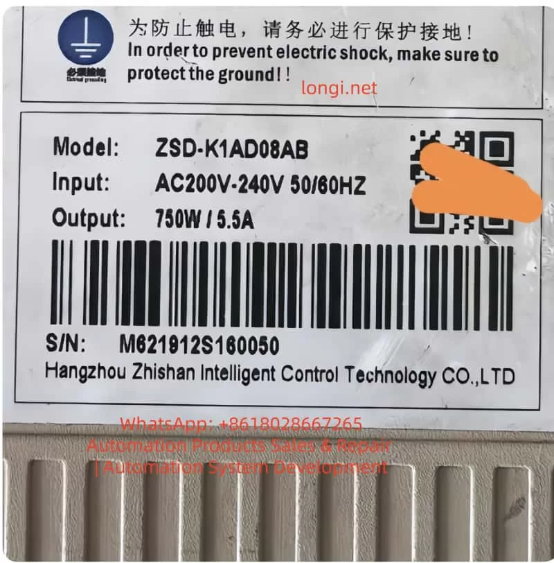
In the realm of industrial automation, the stability of servo systems is the cornerstone of machining precision and production efficiency. The ZSMC K-Series (Zhejiang Zhishan Electric Co., Ltd.), a leading domestic servo system in China, is widely deployed in CNC machine tools, robotics, packaging machinery, and textile equipment. Its core competitive advantage lies in its support for bus-type absolute encoders, enabling high-precision position control and multi-turn position memory without the need for homing sequences upon every power-up.

However, Alarm 27 (Bus Encoder Battery Alarm 1) is one of the most frequent and critical faults encountered in this series. If not addressed promptly, it can lead to production downtime, positional deviations, and even mechanical collisions. This article provides a comprehensive technical analysis of Alarm 27, covering its definition, root causes, operational impact, step-by-step troubleshooting, and preventive maintenance strategies. This guide is designed to serve as a practical reference for field engineers and maintenance personnel.

b.27 alarm

II. Technical Definition and Trigger Mechanism of Alarm 27

1. Fault Definition

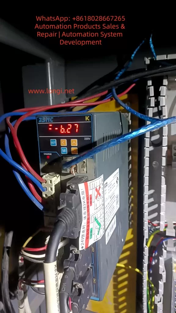
According to the official ZSMC K-Series manual, Alarm 27 corresponds to “Bus Encoder Battery Alarm 1”. The specific technical parameters are:

  • Trigger Condition: The built-in battery voltage of the encoder drops below 2.5V (the critical threshold).
  • Associated Phenomenon: Loss of Multi-turn Position Information (the total count of motor rotations).
  • Drive Action: The drive enters a protection state, inhibiting motor operation. The digital panel displays “27” or a specific battery warning code.

2. Working Principle of Bus-Type Absolute Encoders

Unlike incremental encoders, bus-type absolute encoders (utilizing protocols such as RS485 or CANopen) transmit absolute position data via a serial bus to the drive. This data includes:

  • Single-turn Position: The angular position within one revolution (0–360°).
  • Multi-turn Position: The cumulative count of revolutions since power-on.

The “absolute” nature means the system knows its exact position immediately upon power-up. This capability relies entirely on a backup power source to maintain the counter in non-volatile memory (NVRAM) or specific registers during power outages.

3. Core Function of the Encoder Battery

The encoder typically uses a CR2032 lithium coin cell (nominal voltage 3.0V) for the following purposes:

  • Maintaining Multi-turn Counters: Preserving the count of total motor rotations.
  • Storing Parameters: Saving encoder-specific data (resolution, zero offset, communication baud rate).
  • Powering Static Logic: Supplying the minimal current required for the memory retention circuit.

When the voltage falls below 2.5V, the NVRAM can no longer retain data reliably. Consequently, the multi-turn count resets to zero or becomes invalid, triggering Alarm 27 to prevent the drive from operating with unknown position data.

ZSD-K1AD0-8AB

III. Deep-Dive Root Cause Analysis

While the symptom is “low battery,” the underlying causes are multifaceted. We categorize them into four dimensions: Battery Integrity, Installation/Connection, Component Compatibility, and Environmental Factors.

1. Battery-Specific Factors

  • Natural Lifecycle: A standard CR2032 battery has a lifespan of 3–5 years at 25°C. However, in high-load applications where the encoder communicates frequently via the bus, the discharge rate increases, potentially shortening lifespan to 1–2 years.
  • Quality Issues: Counterfeit or low-quality batteries often have unstable voltage outputs or lower actual capacity. For instance, a factory using generic brand batteries reported Alarm 27 triggering within 6 months of installation.
  • Incorrect Specification: Using a battery with insufficient capacity (e.g., CR2025 instead of CR2032) results in rapid voltage sag under load.

2. Installation and Connection Issues

  • Contact Resistance: Oxidation on battery terminals (copper oxide/verdigris) or loss of spring tension in the battery holder creates high contact resistance. This causes a “voltage drop” where the actual battery voltage might be 2.8V, but the drive detects only 2.3V due to resistance.
  • Polarity Reversal: Installing the battery backward (positive to negative) can cause immediate short circuits or prevent the circuit from charging/discharging correctly.
  • Loose Bus Cabling: A loose connector on the encoder bus cable (e.g., RS485 A/B lines) can cause communication timeouts. Some ZSMC drives interpret communication failures as battery faults as a fail-safe mechanism.

3. Encoder and Drive Hardware Faults

  • Encoder Internal Short Circuit: Corrosion inside the encoder battery compartment or a failed capacitor on the encoder PCB can create a parasitic drain, draining the battery in weeks rather than years.
  • Drive Detection Circuit Failure: The voltage divider resistors or ADC (Analog-to-Digital Converter) chip on the drive’s control board may fail. In this scenario, the battery is fine, but the drive “hallucinates” a low voltage.
  • Protocol Mismatch: If the encoder uses CANopen but the drive is configured for RS485 (or vice versa), the handshake fails. While this usually triggers a communication alarm (e.g., Alarm 28), it can sometimes cascade into Alarm 27 if the drive cannot read the battery status register.

4. Environmental Factors

  • High Temperature: Lithium batteries degrade rapidly above 60°C. The chemical reaction rate doubles for every 10°C increase (Arrhenius equation). In a forging workshop where ambient temperatures reach 70°C, battery life can shrink to less than 12 months.
  • High Humidity: Humidity >80% causes galvanic corrosion on battery contacts, increasing resistance and leading to intermittent voltage detection errors.
  • Electromagnetic Interference (EMI): Proximity to high-power inverters or welders can induce noise on the encoder cables. This noise can corrupt the serial data stream, causing the drive to misinterpret the battery voltage telemetry.

IV. Impact Assessment of Alarm 27

Ignoring Alarm 27 poses significant risks to production and equipment integrity:

1. Operational Impact

  • Hard Lockout: The servo cannot start. In a CNC lathe, this means the spindle cannot turn, halting the entire production line.
  • Homing Failure: After battery replacement, if the multi-turn data is lost, the machine must re-home. If the homing method (e.g., external limit switch) is misconfigured, the axis may drift or fail to find zero.
  • Position Deviation: If the operator forces the motor to run in “relative mode” without multi-turn data, the position feedback will be inaccurate. For example, a robot arm might think it has rotated 10 times when it has only rotated 5, leading to collision or scrap parts.

2. Production and Economic Impact

  • Downtime Costs: For an automotive production line, one hour of downtime can cost tens of thousands of dollars in lost output.
  • Scrap Rates: Position errors lead to out-of-tolerance parts. In precision machining (±0.01mm), a lost multi-turn count can result in 100% scrap rates for a batch.
  • Mechanical Damage: Running a servo without absolute position knowledge can cause the tool post to crash into the chuck or the robot arm to exceed soft limits, damaging gearboxes and ball screws.

3. Long-Term Equipment Health

  • Battery Leakage: If a lithium battery is discharged below 2.0V, it risks leaking electrolyte, which corrodes the encoder PCB, permanently destroying the encoder.
  • Drive Stress: Repeated power cycles while the alarm is active can stress the drive’s IGBT modules and DC bus capacitors.

V. Troubleshooting and Resolution Procedures

(一) Systematic Troubleshooting Flow

Step 1: Confirm the Alarm Code

  • Verify via the drive’s 7-segment LED display or the ZSMC Studio software that the code is specifically “27” (Bus Encoder Battery Alarm).
  • Note: Check for coupled alarms. If Alarm 28 (Communication Error) is present, address the cabling first.

Step 2: Measure Battery Voltage

  1. Disconnect main power to the drive (wait 5 minutes for capacitors to discharge).
  2. Open the encoder battery cover (usually located on the rear or side of the motor).
  3. Use a multimeter (DC Voltage mode) to measure across the battery terminals:
    • ≥ 2.8V: Battery is healthy; investigate connection or drive logic.
    • 2.5V – 2.8V: Battery is nearing end-of-life; schedule replacement.
    • < 2.5V: Battery is dead; immediate replacement required.

Step 3: Inspect Physical Connections

  • Battery Holder: Check spring tension. Clean oxidized terminals with isopropyl alcohol and a fiberglass pen.
  • Bus Cable: Unplug and re-plug the encoder cable. Ensure the shielding is grounded properly. Check for pinched wires or broken conductors.
  • Mounting: Verify the encoder coupling set screw is tight (Torque: 5–8 N·m for ZSMC K-series).

Step 4: Verify Compatibility via Software

  • Connect to ZSMC Studio (or the handheld debugger).
  • Read Encoder Information: Confirm the model matches the drive configuration (e.g., “ZSMC-E-2048-4-24V”).
  • Check Protocol Settings: Ensure Pn001 (Encoder Type) is set to “Bus Absolute Encoder” (not “Incremental” or “Sin-Cos”).

Step 5: Isolate the Faulty Component

  • Swap Test: Replace the battery. If the alarm persists, swap the encoder with a known-good spare.
    • Alarm disappears: Original encoder is faulty (internal circuit failure).
    • Alarm remains: The drive’s detection circuit is likely damaged (requires board-level repair or drive replacement).

(二) Detailed Resolution Operations

1. Replacing the Encoder Battery

Tools: Multimeter, Phillips screwdriver, CR2032 battery (Genuine ZSMC or reputable brand like Panasonic/Sony).
Procedure:

  1. Power Down: Cut main power and wait 5 minutes.
  2. Access: Remove the encoder cover. Extract the old battery (avoid touching the PCB).
  3. Install: Insert the new battery with correct polarity (+ to +).
  4. Secure: Tighten the cover.
  5. Power Up: Restore power.

Critical Note: While some encoders support hot-swapping, ZSMC K-series recommends power-off replacement to avoid bus contention. After replacement, use ZSMC Studio to perform a “Battery Learn” (Pn002 = 1) to recalibrate the drive’s voltage detection.

2. Restoring Multi-Turn Position (Homing)

Once the battery is replaced, the multi-turn count is lost. You must re-establish the mechanical zero. ZSMC K-series supports three methods:

  • Method A: External Home (Recommended)
    1. Install a proximity sensor at the mechanical zero point.
    2. Set Pn003 (Homing Mode) = 2 (External Signal).
    3. Set Pn004 (Home Input Type) = 1 (NPN Normally Open).
    4. Press the “ORIGIN” button on the keypad. The motor will creep toward the sensor, stop upon detection, and set the position to 0.
  • Method B: Z-Phase Home
    1. Use the encoder’s Z-pulse (once per revolution).
    2. Set Pn003 = 1.
    3. The drive finds the Z-pulse edge and sets it as zero. Note: This does not reset multi-turn count unless combined with a specific “Clear Multi-turn” command.
  • Method C: Software/Manual Setting
    1. Connect ZSMC Studio.
    2. Manually rotate the axis to the mechanical zero.
    3. Click “Set Current Position as Zero” in the software.
    4. For multi-turn encoders, you may need to execute a “Multi-turn Clear” function (consult the specific encoder manual, e.g., ZSMC E-series “MULTI-TURN RESET”).

3. Addressing Environmental & Connection Issues

  • Corrosion: Apply dielectric grease to battery terminals to prevent future oxidation.
  • Vibration: Use cable ties to secure the bus cable to the motor body, preventing connector fatigue.
  • Heat: Install a forced-air cooling fan (≥5 CFM) directed at the encoder, or maintain the servo cabinet temperature below 30°C using an air conditioner.
  • Humidity: Place silica gel desiccants inside the cabinet or pot the encoder connector with epoxy for IP65 protection.

VI. Case Studies

Case 1: Intermittent Alarm Due to Poor Contact

Symptom: A ZSMC-K-110ST-M06025 servo on a CNC lathe triggered Alarm 27 intermittently. Replacing the battery did not fix it.
Investigation:

  • Measured battery voltage: 2.9V (Good).
  • Inspected holder: The positive spring was flattened and oxidized.
    Resolution:
  • Bent the spring to restore tension.
  • Cleaned contacts with contact cleaner.
  • Result: Alarm cleared permanently.

Case 2: Premature Battery Failure in High Heat

Symptom: Robotic servos in a forging plant triggered Alarm 27 every 6 months (expected life: 3 years).
Investigation:

  • Ambient temp near motor: 75°C.
  • Battery voltage: 2.2V (Dead).
    Resolution:
  1. Replaced batteries.
  2. Installed aluminum heat sinks (100cm²) on the motor backs.
  3. Installed an industrial air conditioner in the cabinet (set to 25°C).
    Result: Battery life extended to 2 years.

Case 3: Encoder Internal Short Circuit

Symptom: Packaging machine servo triggered Alarm 27 immediately after battery replacement. Could not home.
Investigation:

  • ZSMC Studio read “Battery Voltage: 2.1V” despite new battery.
  • Swapped encoder: Alarm cleared.
  • Disassembled old encoder: Found corrosion on battery terminals and a shorted capacitor on the PCB (due to 85% humidity).
    Resolution:
  • Replaced encoder.
  • Installed industrial dehumidifier in the factory (humidity controlled to 60%).

VII. Preventive Maintenance & Strategy

1. Scheduled Battery Replacement

  • Standard Environment (25°C): Check voltage every 12 months. Replace if < 2.8V.
  • High Temp (>40°C): Check every 6 months.
  • High Humidity (>70%): Check every 3 months.

2. Environmental Control

  • Temperature: Maintain servo cabinet at 20–30°C.
  • Humidity: Keep relative humidity at 40–60%.
  • EMI: Use shielded twisted-pair cables for the bus. Ground the shield at the drive end only. Keep encoder cables 30cm away from power lines.

3. Component Standardization

  • Batteries: Use only CR2032 from reputable sources (Panasonic, Sony, or ZSMC OEM).
  • Encoders: Use ZSMC-approved absolute encoders (e.g., ZSMC E-series) to ensure protocol compatibility.
  • Cables: Use factory-made bus cables (e.g., ZSMC-CABLE-RS485) to avoid impedance mismatch.

4. Digital Monitoring

  • ZSMC Studio Alerts: Configure the software to trigger a “Pre-Alarm” when battery voltage drops to 2.8V, allowing maintenance during planned downtime.
  • Maintenance Logs: Record battery changes in a logbook (Date, Axis, Voltage, Technician).

VIII. Common Pitfalls & Precautions

1. Pitfall: Replacing Battery Without Homing

  • Consequence: The drive runs in relative mode, accumulating position errors.
  • FixAlways perform a homing sequence after battery replacement.

2. Pitfall: Using Non-Standard Batteries

  • Consequence: AA/AAA batteries (1.5V) cannot power the encoder circuitry (requires 3.0V+).
  • Fix: Strictly use CR2032 (3V) or the specific model recommended in the manual.

3. Pitfall: Ignoring the Bus Cable

  • Consequence: Loose cables cause “ghost” battery alarms due to data corruption.
  • Fix: Torque screws on connectors to 0.5 N·m and use thread locker if necessary.

4. Safety Precautions

  • Electrical Shock: Always discharge the drive DC bus (wait 5 mins) before touching internal components.
  • Data Loss: Some encoders lose parameters if power is removed too long. Replace batteries quickly (within 2 minutes) if the manual specifies “live replacement.”
  • Professional Repair: Do not solder on encoder PCBs unless trained; ESD can destroy the chip.

IX. Conclusion

Alarm 27 in the ZSMC K-Series servo system is a critical indicator of battery voltage depletion leading to multi-turn position loss. While the fix often seems as simple as replacing a coin cell, the root causes range from environmental stress to hardware failures.

For engineers, mastering the voltage verification processhoming procedures, and environmental control is essential. As technology evolves, battery-less absolute encoders (using supercapacitors or energy harvesting) are emerging, promising to eliminate this issue entirely. However, until then, a proactive battery maintenance strategy is the most cost-effective way to ensure servo reliability.

Final Recommendation: Integrate battery checks into your daily “Gemba Walk” or start-up checklist. The cost of a CR2032 battery is negligible compared to the cost of a crashed machine or a day of lost production.

Posted on

INFICON UL5000 Leak Detector Error 52 Analysis: Causes of Low TMP Frequency and Systematic Troubleshooting Guide

1. Introduction

In helium mass spectrometer leak detection systems, operational stability depends heavily on the coordination of the vacuum system. The INFICON UL5000, widely used in industrial and laboratory environments, is a high-precision leak detector whose performance is closely tied to the functionality of its turbomolecular pump (TMP) and backing vacuum system.

A commonly encountered alarm in field applications is:

ERROR (52): TMP frequency is too low

This fault prevents the system from entering detection mode and can disrupt production or testing processes. This article provides a structured technical analysis of this error, including system principles, root causes, and practical troubleshooting methods.


ERROR 52 fault of the UL5000

2. System Architecture and Working Principle

Understanding Error 52 requires a clear understanding of the UL5000 system architecture.

The UL5000 consists of the following key subsystems:

  1. Vacuum System
    This includes the backing pump (such as a rotary vane or dry pump) and the turbomolecular pump. The backing pump creates the initial vacuum, while the TMP generates high vacuum conditions.
  2. Detection System
    This includes the mass spectrometer, ion source, and detector, responsible for helium detection at high sensitivity.
  3. Control System
    Comprising the frequency converter, control board, and user interface, this system manages the operation of all components.
  4. Pressure Monitoring System
    Multiple pressure sensors monitor system pressure in real time to ensure safe and stable operation.

3. Critical Startup Logic of the TMP

A key misconception is that the turbomolecular pump can start under any condition. In reality, its operation depends on the pre-vacuum level.

The startup sequence of the UL5000 is as follows:

First, the backing pump starts and reduces system pressure to a rough vacuum range.
Second, once the pressure reaches a defined threshold, the control system enables the TMP.
Third, the TMP accelerates to its nominal operating speed.
Finally, the system enters stable detection mode.

If the required vacuum level is not achieved, the TMP cannot accelerate properly.


4. Technical Meaning of Error 52

Error 52 indicates that the turbomolecular pump frequency is below the required operating level.

This implies:

The TMP has not reached its nominal rotational speed.
The control system has detected an abnormal operating condition and triggered protection.

It is important to note that this error does not necessarily mean that the pump itself is damaged. It is often a system-level issue.


550-500A UL5000

5. Root Cause Analysis

Based on field experience, the causes of Error 52 can be categorized into three main groups.

5.1 Insufficient Vacuum Conditions

This is the most common cause.

If the system pressure is too high, the gas load on the TMP increases significantly, preventing it from reaching full speed.

Typical reasons include:

Degraded or malfunctioning backing pump
Vacuum leaks in the system
Loose or improperly sealed connections
Aging or damaged sealing components

Typical symptoms include slow TMP acceleration and delayed fault occurrence.


5.2 Mechanical Issues in the Turbomolecular Pump

The TMP operates at extremely high rotational speeds and requires precise mechanical balance.

Possible issues include:

Bearing seizure or increased friction
Contamination from oil vapor or moisture
Rotor imbalance or deformation

These issues are often accompanied by abnormal noise or unstable operation.


5.3 Drive System Failure

The TMP is driven by a dedicated frequency converter.

Possible faults include:

Failure of the drive module
Unstable or insufficient power supply
Control signal issues

In such cases, the TMP may not start at all, and the error may appear immediately after power-up.


6. Systematic Troubleshooting Procedure

A structured troubleshooting approach should follow a sequence from simple to complex checks.

Step 1: Check the backing pump
Ensure the pump is operating normally and achieving sufficient vacuum.

Step 2: Inspect system sealing
Verify that all connections, flanges, and seals are intact and leak-free.

Step 3: Observe TMP behavior
Determine whether the pump starts, and check for abnormal noise or vibration.

Step 4: Verify electrical connections
Inspect power supply cables and control wiring for stability and proper connection.

Step 5: Perform system reset
Power off the system, wait for a short period, and restart.


7. Typical Fault Distribution

Based on field repair data, the causes of Error 52 are typically distributed as follows:

Most cases are related to insufficient vacuum conditions
Vacuum leakage is the second most common cause
Mechanical TMP failures are less frequent
Drive system failures are relatively rare

This distribution highlights the importance of focusing on the vacuum system before replacing major components.


8. Common Misdiagnosis and Risks

Incorrect diagnosis can lead to unnecessary costs and delays.

Common mistakes include:

Assuming the TMP is faulty without verification
Replacing expensive components without checking the vacuum system
Ignoring environmental factors

A structured diagnostic approach can significantly reduce repair costs and downtime.


9. Environmental Factors

Operating conditions play a significant role in system performance.

High humidity can introduce moisture into the system, affecting TMP operation.
High temperature accelerates component aging.
Long idle periods can lead to bearing degradation or seal failure.

These factors should be considered during troubleshooting and maintenance.


10. Preventive Maintenance Recommendations

To reduce the likelihood of Error 52, regular maintenance is essential.

Recommended practices include:

Periodic inspection of the backing pump
Replacement or maintenance of seals
Keeping the system clean and dry
Avoiding TMP startup under high-pressure conditions
Running the system periodically if it is not in regular use


11. Conclusion

Error 52 on the INFICON UL5000 is a system-level issue rather than a simple component failure. It indicates that the turbomolecular pump cannot reach its required operating speed under current conditions.

In most cases, the root cause lies in insufficient vacuum or system leakage, rather than a failure of the TMP itself.

A systematic troubleshooting approach focusing on the vacuum system should always be the first step, followed by inspection of the TMP and drive system if necessary.

Posted on

In-Depth Analysis and Systematic Troubleshooting Guide for ERR45 Fault in Zhengshun Servo ZS100 Series

I. Introduction

In the field of industrial automation, the Zhengshun Servo ZS100 series is widely applied in core scenarios such as CNC machine tools, industrial robots, packaging machinery, and textile equipment due to its high precision, rapid response, and wide speed – regulation range. However, during long – term operation, the ERR45 fault (motor over – temperature) is one of the most common alarms in the ZS100 series. According to the fault statistics of a servo manufacturer in 2023, ERR45 accounts for 18% of all faults. If not handled promptly, it may lead to motor winding burnout, bearing seizure, and even equipment shutdown and production interruption, causing significant losses to enterprises.

Based on the technical documents of the ZS100 series, on – site maintenance experience, and fault cases, this article systematically analyzes the solution logic of the ERR45 fault from the perspectives of fault definition, detection principle, cause analysis, troubleshooting steps, and preventive measures, providing an actionable reference plan for engineering technicians.

II. Definition and Detection Principle of ERR45 Fault

1. Fault Definition

ERR45 is a protection alarm for abnormal motor temperature in the Zhengshun Servo ZS100 series drive. The trigger condition is that the motor temperature exceeds the threshold set by the drive (the default threshold is 130°C – 150°C, depending on the motor insulation class). When the temperature exceeds the threshold, the drive immediately cuts off the output, the panel displays “ERR45”, and locks the fault state (which can only be restarted after reset).

2. Temperature Detection Principle

The ZS100 series collects temperature signals through a built – in temperature sensor in the motor. There are two common types of sensors:

  • PTC Thermistor (Positive Temperature Coefficient): At 25°C, its resistance is approximately 100Ω – 500Ω. As the temperature rises, the resistance increases sharply (the Curie point is about 120°C – 150°C). When it exceeds the Curie point, the resistance suddenly jumps to infinity, triggering protection.
  • PT100 Platinum Resistor (Linear Characteristics): At 0°C, its resistance is 100Ω, with a temperature coefficient of about 0.00385Ω/Ω/°C and high precision (±0.1°C), suitable for high – precision temperature detection.

The temperature detection process of the drive is as follows:

  • The sensor converts the temperature signal into a resistance value.
  • The signal conditioning circuit (amplification and filtering) converts the resistance value into a voltage signal.
  • The AD conversion chip (such as a 12 – bit AD) converts the voltage signal into a digital quantity.
  • The internal algorithm of the drive converts the digital quantity into a temperature value (for example, the temperature calculation formula for PT100: T=R0​×αRt​−R0​​, where Rt​ is the current resistance, R0​ is the resistance at 0°C, and α is the temperature coefficient).
  • The comparator compares the calculated temperature with the set threshold. If it exceeds the threshold, the ERR45 alarm is triggered.
ERR45 fault of ZS100

III. In – Depth Cause Analysis of ERR45 Fault

The essence of ERR45 is that “the motor temperature exceeds the protection threshold”, but the reasons for the temperature rise need to be analyzed from six dimensions: the motor side, the fan side, the wiring side, the drive side, the load side, and the environmental side, as follows:

(I) Motor Side: Real Overheating or Sensor Fault

1. Real Overheating (Abnormal Motor Temperature)

  • Overload Operation: When the load torque exceeds the rated torque of the motor (for example, the rated torque of the ZS100 – 22kW motor is 70N·m, and if the load reaches 80N·m, it is overloaded), the current increases (exceeding the rated current), and the winding heating increases.
  • Long – term High – load Operation: The motor runs continuously for 24 hours, and the heat dissipation cannot keep up, causing the temperature to accumulate and exceed the threshold.
  • Poor Heat Dissipation: Dust accumulation on the motor heat sink, coverage by debris (such as oil stains from cutting fluid splashing), or a high ambient temperature (workshop temperature > 40°C) reduce the heat dissipation efficiency.
  • Motor Faults:
    • Winding Short – circuit: The insulation of the winding ages (the insulation life is halved for every 10°C increase in temperature), resulting in an inter – phase short – circuit, a sudden increase in current, and increased heating.
    • Bearing Damage: The bearing grease fails (carbonization due to high temperature) or the ball bearings wear, causing friction between the rotor and the stator and generating a large amount of heat.
    • Rotor Jamming: Foreign objects (such as iron filings) enter the motor, or the bearing seizes, preventing the rotor from rotating. The current increases sharply (up to 5 – 10 times the rated current), causing instant overheating.

2. Sensor Fault (False Temperature Alarm)

  • Sensor Damage: The PTC thermistor breaks down (resistance is 0Ω), or the PT100 platinum resistor is open – circuit (resistance is infinite).
  • Improper Sensor Installation: It is not tightly attached to the motor winding (for example, installed on the heat sink instead of near the winding), causing the detected temperature to be lower than the actual winding temperature.
  • Sensor Type Mismatch: The drive parameters are set to “PT100”, but a PTC sensor is actually used, resulting in incorrect temperature calculation.

(II) Fan Side: Heat Dissipation Failure

The ZS100 series motor is usually equipped with a forced air – cooling fan (voltage AC220V, speed 1500rpm). Fan failure is a common cause of ERR45:

  • Fan Does Not Rotate: The fan motor is damaged (winding burnout), or there is a power supply fault (loose wiring, fuse blowout).
  • Insufficient Fan Speed: Dust accumulation on the fan blades (such as in a workshop with a lot of dust) or bearing wear (high rotational resistance) reduce the air volume (the normal air volume is about 0.5m³/min. If it drops to 0.2m³/min, heat dissipation fails).
  • Incorrect Fan Direction: The fan rotates in reverse (such as due to incorrect wiring phase sequence), causing air to be blown out from the inside of the motor instead of being drawn in, completely losing the heat dissipation effect.

(III) Wiring Side: Signal Transmission Fault

Wiring problems of the temperature sensor can prevent the drive from correctly collecting the temperature signal:

  • Broken Wire: The wire breaks due to long – term vibration (for example, the motor junction box is not fixed), or is squeezed by mechanical parts (such as the machine tool protective door clamping the wire).
  • Poor Contact: The wiring terminals are oxidized (for example, copper terminals develop green rust), or the screws are loose, increasing the resistance (for example, the contact resistance increases from 0.1Ω to 10Ω), causing abnormal AD conversion values.
  • Polarity Error: The PT100 sensor requires “three – wire” wiring (to compensate for wire resistance). If it is connected as “two – wire”, the detected temperature value will be higher (for example, the actual temperature is 100°C, but the detected temperature is 120°C).

(IV) Drive Side: Detection Circuit Fault

If the motor, fan, and wiring are all normal, a fault in the drive’s temperature detection circuit should be suspected:

  • AD Conversion Chip Damage: For example, if the ADS1115 chip fails, the conversion of the resistance value to the temperature value is incorrect (for example, the actual temperature is 100°C, but it is displayed as 150°C).
  • Comparator Fault: For example, if the LM393 comparator is damaged, the threshold judgment is incorrect (for example, the threshold is set to 140°C, but the comparator triggers the alarm at 120°C).
  • Parameter Setting Errors:
    • The temperature threshold is set too low (for example, for an F – class insulation motor, the threshold is set to 120°C, while the actual allowable temperature is 155°C).
    • The sensor type is set incorrectly (for example, PTC is actually used, but the parameter is set to PT100).
    • The filtering time is set too short (for example, 10ms), causing temperature signal fluctuations and false alarms.

(V) Load Side: Mechanical Transmission Abnormalities

Mechanical load problems can indirectly cause motor overheating:

  • Transmission Jamming: Poor lubrication of the lead screw (lack of oil) or bearing damage (ball bearing seizure) requires the motor to overcome greater resistance, increasing the current.
  • Excessive Load: For example, the feeding mechanism of packaging machinery is jammed, causing the motor torque to exceed the rated value.
  • Coupling Misalignment: The radial deviation between the motor shaft and the load shaft is > 0.05mm, and the axial deviation is > 0.03mm, causing the motor shaft to bear additional radial forces and increasing friction heating.

(VI) Environmental Side: Deterioration of Heat Dissipation Conditions

  • High Workshop Temperature: In summer, if the workshop temperature exceeds 40°C, the motor’s heat dissipation capacity decreases (the heat dissipation efficiency is inversely proportional to the ambient temperature).
  • Poor Ventilation: There are obstacles (such as shelves and equipment) around the motor, preventing the hot air from being discharged.
  • Heat Source Interference: There are heaters, high – frequency welding machines, and other heat sources near the motor, increasing the ambient temperature.
ZS100T015-C

IV. Systematic Troubleshooting Steps for ERR45 Fault

When troubleshooting ERR45, the principle of “from simple to complex and from external to internal” should be followed to avoid blind disassembly. The following is a standardized troubleshooting process:

Step 1: Reset the Fault and Confirm Whether It is a False Alarm

Operation: Press the “reset” key on the drive panel (or power off and restart). If the fault disappears, it may be due to occasional interference (such as power supply fluctuations or instantaneous abnormal sensor signals). If the fault recurs, further troubleshooting is required.

Step 2: Check the Temperature Sensor Wiring (Easiest to Check)

Tools: Multimeter (resistance range), screwdriver.
Operation:

  • Turn off the drive power and wait for 5 minutes (for capacitor discharge).
  • Remove the motor junction box and find the temperature sensor terminals (marked as “TH” or “TEMP”).
  • For a PTC sensor (two wires): Measure the resistance between the two ends. At 25°C, it should be 100Ω – 500Ω (depending on the model). If the resistance is infinite (broken wire) or 0Ω (short – circuit), replace the wire or sensor.
  • For a PT100 sensor (three wires): Measure the resistance between the “A – B” wires (about 100Ω at 25°C). The resistances between “A – C” and “B – C” wires should be equal (to compensate for wire resistance). If the resistances are abnormal, check the wiring or sensor.
  • Check whether the terminals are oxidized or loose. Polish them with sandpaper or tighten them again.

Step 3: Check the Motor Fan (Key Heat – Dissipation Component)

Tools: Multimeter (voltage range), tachometer (or the “Tachometer” mobile app), compressed air.
Operation:

  • Power on and start the motor (run at low speed), and observe whether the fan rotates.
  • If the fan does not rotate: Measure the fan power supply voltage (should be AC220V). If there is no voltage, check the drive’s fan output terminals or wiring. If there is voltage, it means the fan motor is damaged and needs to be replaced.
  • If the fan rotates: Use a tachometer to measure the speed (normal 1500rpm ± 10%). If the speed is insufficient, clean the blade dust with compressed air or lubricate the bearing (add a drop of engine oil).
  • Check the fan direction: Feel the airflow with your hand. Air should be drawn in from the outside of the motor (blown from the heat sink to the inside of the motor). If it rotates in reverse, adjust the wiring phase sequence.

Step 4: Detect the Actual Motor Temperature (Determine Whether It is Overheated)

Tools: Infrared thermometer (such as FLUKE TiS75), megohmmeter (500V).
Operation:

  • Run the motor until the fault is triggered (or simulate the load), and use an infrared thermometer to measure the motor housing (normal ≤ 80°C), heat sink (normal ≤ 100°C), and winding (measured through the junction box, normal ≤ 130°C, F – class insulation allows 155°C).
  • If the temperature exceeds the threshold, it means the motor is really overheated, and the load or the motor itself needs to be checked.
  • After shutdown, use a megohmmeter to measure the winding insulation resistance (between phases and to the ground). It should be > 10MΩ normally. If it is < 1MΩ, it means the winding is damp or the insulation is aged, and the motor needs to be dried or replaced.

Step 5: Troubleshoot the Load and Mechanical Transmission (Indirect Causes)

Tools: Torque sensor, dial indicator, lubricating grease.
Operation:

  • Use a torque sensor to measure the load torque (for example, the rated torque of the ZS100 – 22kW motor is 70N·m. If it exceeds 80N·m, it is overloaded). Adjust the load (such as reducing the feeding amount or repairing the jammed lead screw).
  • Use a dial indicator to measure the coupling alignment: the radial deviation should be ≤ 0.05mm, and the axial deviation should be ≤ 0.03mm. If it exceeds the standard, re – adjust the coupling.
  • Check the lubrication of mechanical transmission components: whether the lead screw and bearings are short of oil. Add lubricating grease (such as lithium – based grease).
  • Manually rotate the motor shaft (power off): if it is jammed, it means there is a problem with the bearing or rotor, and the motor needs to be disassembled for inspection.

Step 6: Check the Drive’s Temperature Detection Circuit (Last Step)

Tools: Oscilloscope, multimeter, replacement sensor.
Operation:

  • If all the above steps are normal, disassemble the drive and find the temperature detection circuit (usually on the control board, marked as “TEMP IN”).
  • Use an oscilloscope to measure the sensor signal waveform: the resistance change of the PTC sensor should be proportional to the temperature, and the voltage signal of the PT100 should change linearly.
  • Replace the temperature sensor (use a new sensor of the same model). If the fault disappears, it means the original sensor is damaged.
  • If the fault still exists, check the power supply voltage (should be 5V) and output signal of the AD conversion chip (such as ADS1115) for normality, or replace the control board.

Step 7: Improve the Environment and Heat Dissipation (Prevent Recurrence)

Tools: Thermometer, ventilation equipment, compressed air.
Operation:

  • Measure the workshop temperature. If it is > 40°C, install an air conditioner or industrial fan (aimed at the motor heat sink).
  • Clean the debris around the motor (such as cutting fluid buckets and tools) to ensure a clear heat dissipation channel.
  • Apply thermal conductive silicone grease (such as Shin – Etsu 7921) on the motor heat sink to improve heat dissipation efficiency.
  • For motors that run under long – term high – load conditions, add an external heat sink (such as an air – cooled heat sink).

V. Analysis of Typical Cases

Case 1: False Alarm Due to Wiring Breakage

Fault Phenomenon: A ZS100 – 15kW servo motor on a CNC lathe suddenly reported ERR45 during operation and could not be started after reset.
Troubleshooting Process:

  • Check the temperature sensor wiring and find that one wire of the PTC sensor is broken at the junction box (due to long – term vibration, the wire – terminal welding joint is detached).
  • Re – weld the wire and perform insulation treatment (wrap it with heat – shrinkable tubing).
  • Power on for testing, and the fault disappears. The motor returns to normal.
    Cause: The wire breakage interrupts the sensor signal, and the drive misjudges it as “infinite temperature”, triggering ERR45.
    Lesson: The motor junction box should be firmly fixed to prevent wire breakage due to vibration.

Case 2: Overheating Due to Fan Dust Accumulation

Fault Phenomenon: A ZS100 – 7.5kW servo motor on a packaging machine frequently reported ERR45 (1 – 2 times a day). It could continue to run after reset, but the frequency gradually increased.
Troubleshooting Process:

  • Check the fan and find that the blades are covered with dust (the workshop is a flour mill with a lot of dust), and the speed is only 800rpm (normal 1500rpm).
  • Clean the fan blades with compressed air and add lubricating grease to the bearing.
  • Run for 24 hours, and the fault does not recur.
    Cause: Dust accumulation on the fan reduces the speed and heat dissipation capacity, causing the motor temperature to gradually rise to the threshold.
    Lesson: In dusty environments, the fan should be cleaned regularly, preferably once a month.

Case 3: Real Overheating Due to Load Overload

Fault Phenomenon: A ZS100 – 22kW joint motor on an industrial robot reported ERR45. The infrared thermometer showed that the motor temperature reached 160°C (exceeding the 155°C allowed for F – class insulation).
Troubleshooting Process:

  • Check the load and find that the lubrication of the robot’s lead screw is poor, causing the torque to increase from 70N·m to 90N·m (overload).
  • Disassemble the lead screw, clean the old lubricating grease, and add new lithium – based grease.
  • Adjust the load (reduce the grasping weight of the robot arm). After operation, the torque returns to 70N·m, and the temperature drops to 110°C.
    Cause: Load overload increases the motor current (from 46.5A to 55A), increasing the winding heating and exceeding the temperature threshold.
    Lesson: The load torque should be monitored regularly to avoid long – term overload operation.

VI. Preventive Measures for ERR45 Fault

1. Regular Maintenance Plan (Key)

Maintenance CycleMaintenance Content
MonthlyCheck the fan operation and clean the dust; measure the sensor resistance (PTC: 100Ω – 500Ω, PT100: 100Ω); check whether the wiring terminals are loose.
QuarterlyMeasure the motor winding insulation resistance (> 10MΩ); check the lubrication of mechanical transmission (add grease to the lead screw and bearings); check the coupling alignment (deviation ≤ 0.05mm).
Semi – annuallyClean the dust on the motor heat sink; calibrate the temperature sensor (compare with a standard thermometer); check the drive’s cooling fan (clean the heat sink).
AnnuallyReplace the motor lubricating grease (except for sealed bearings); replace the temperature sensor (if it has been used for more than 3 years); check the drive’s temperature detection circuit (measure the waveform with an oscilloscope).

2. Parameter Setting Optimization

  • Temperature Threshold: Set it according to the motor insulation class (set it to 140°C for F – class and 160°C for H – class) to avoid false alarms due to a too – low threshold or loss of protection due to a too – high threshold.
  • Sensor Type: Ensure that the drive parameters are consistent with the actual sensor (set PTC as “PTC” and PT100 as “PT100”).
  • Filtering Time: Set it to 100ms – 500ms (avoid false alarms due to signal fluctuations), but not too long (such as > 1s, which will delay protection).

3. Environmental Improvement

  • Control the workshop temperature within 25°C – 35°C (install an air conditioner or industrial fan).
  • Prohibit stacking debris within 1 meter around the motor to ensure a clear heat dissipation channel.
  • For high – temperature environments (such as foundry workshops), add a water – cooled heat sink to the motor (instead of air – cooling).

4. Load Monitoring

  • Install a torque sensor or current sensor to monitor the motor load in real – time (alarm when the torque exceeds 110% of the rated value).
  • Set overload protection (set the “overload current threshold” in the drive parameters, such as 120% of the rated current. When it is exceeded, cut off the output).
  • Avoid frequent start – stop (for example, starting more than 5 times per minute will cause heat accumulation in the motor).

VII. Conclusion

The ERR45 fault is a “temperature protection signal” for the ZS100 series servo system, and its core logic is that “the motor temperature exceeds the safety threshold”. When troubleshooting, start with simple components such as wiring and fans, and gradually delve into the motor, load, and drive. Use tools (multimeter, infrared thermometer, oscilloscope) to quickly locate the fault point.

The key to preventing ERR45 is regular maintenance (cleaning the fan and checking the wiring), optimizing parameters (correctly setting the temperature threshold), improving the environment (controlling the workshop temperature), and monitoring the load (avoiding overload). Engineering technicians should master the detection principle and troubleshooting process of the fault to solve problems in a timely manner and ensure the stable operation of the equipment.

For ZS100 series users, it is recommended to establish a fault record (record the fault time, phenomenon, troubleshooting process, and solution), and take preventive measures in advance (such as cleaning the fan before summer) through data statistical analysis (such as the high – incidence season and equipment of ERR45).

Posted on

In-Depth Analysis and Troubleshooting Guide for ERR46 Fault in Zhensun Servo ZS100 Series

Introduction

In the field of industrial automation, servo drives serve as the core hub between hydraulic systems and motor control. Their stability directly determines the production efficiency of equipment such as machine tools, injection molding machines, and packaging machinery. As a mainstream product in the domestic low-to-mid-end market, the Zhensun Servo ZS100 series is widely used in various hydraulic drive scenarios due to its high cost-performance ratio. However, ERR46 (Hydraulic Pressure Sensor Fault) is one of the most frequently reported issues by users. This fault causes the servo system to shut down immediately, potentially interrupting production processes or, in severe cases, damaging hydraulic components (e.g., pumps, valves).

This article combines Zhensun Servo technical documentation, on-site maintenance cases, and sensor principles to provide a comprehensive breakdown of the ERR46 fault from four dimensions: fault mechanism, cause investigation, resolution steps, and preventive measures, offering maintenance personnel an actionable troubleshooting guide.


ERR46 fault of the zs100

1. The Underlying Logic of ERR46: The “Perception-Feedback” Mechanism of the Hydraulic Pressure Sensor

To resolve ERR46, one must first understand the role of the hydraulic pressure sensor and the drive’s fault-triggering logic.

1.1 Core Function of the Hydraulic Pressure Sensor

The hydraulic pressure sensor acts as the “nerve ending” of the hydraulic system. Essentially, it is a pressure-to-electrical signal converter. The ZS100 series typically employs piezoresistive sensors (low cost, high reliability). The working principle is as follows: when hydraulic oil pressure acts on the sensor’s sensitive diaphragm, the diaphragm deforms, causing a change in the resistance of the internal piezoresistive elements. This change is converted into a 0-10V DC analog signal (or 4-20mA for some models) via a Wheatstone bridge and fed back to the servo drive.

The drive adjusts the motor speed based on this signal to ensure the hydraulic system pressure remains stable within the set range (e.g., 10-15MPa for machine tool clamping mechanisms, 0.5-1MPa for lubrication systems). For example:

  • When clamping cylinder pressure is insufficient, the drive increases motor speed to boost the pump’s output pressure.
  • When the pressure reaches the set value, the drive reduces speed to maintain constant pressure.

1.2 Trigger Conditions for ERR46

The ZS100 series drive collects sensor signals through analog input channels (e.g., parameter L0.11). Internal signal detection circuits monitor the following metrics in real-time:

  • Range: Whether the sensor signal exceeds the drive’s set threshold (e.g., if 0-10V corresponds to 0-10MPa, a signal exceeding 10V triggers an over-range alarm).
  • Signal Stability: Whether signal fluctuation exceeds 0.5V within 1 second (e.g., signal jitter caused by vibration).
  • Signal Continuity: Whether “signal loss” occurs (e.g., wiring disconnection resulting in a sustained 0V signal for over 1 second).
  • Parameter Matching: Whether the sensor’s zero point (voltage at no pressure) and full scale (voltage at max pressure) match the drive parameters.

If any of these metrics are abnormal, the drive triggers an ERR46 fault and cuts off motor output to prevent the hydraulic system from running out of control and damaging equipment.


2. Common Causes and Troubleshooting Process for ERR46

Based on field maintenance data, the top three causes of ERR46 are: loose wiring (45%), sensor damage (30%), and parameter errors (20%). The remaining 5% are attributed to internal drive circuit faults (e.g., damage to the analog input module). Below is the standardized troubleshooting process:

2.1 Step 1: Safety First (Mandatory!)

Servo drives contain high-voltage capacitors (which may retain over 300V even after power-off). Before operation:

  1. Disconnect the drive’s main power supply (AC380V).
  2. Wait for 5 minutes to allow the capacitors to discharge.
  3. Use a multimeter to measure the voltage at the drive terminals (e.g., L1, L2, L3) to confirm they are de-energized before proceeding.

2.2 Step 2: Check Sensor Wiring (Most Common Cause)

Wiring issues are the “number one killer” of ERR46 faults, especially in high-vibration environments (e.g., machine tools) where terminal looseness and cable damage are common.

Troubleshooting Steps:

  1. Locate Terminals: Open the drive panel and find the hydraulic pressure sensor terminals (usually marked “PRESSURE SENSOR” or “OIL PRESSURE,” corresponding to terminals like X3-1 (+24V), X3-2 (Signal Output), X3-3 (0V/GND)).
  2. Check for Looseness: Gently shake the terminals with a screwdriver. If poor contact between the terminal and wire core is found (e.g., exposed core), re-crimp or replace the terminal.
  3. Check Cable Integrity: Inspect the sensor cable for crushing, breaking, or fraying (especially near bends close to the sensor or drive). Use a multimeter continuity setting to test the cable (signal wire resistance should be <0.5Ω).
  4. Check Shielding: The sensor cable must be shielded, with the shield grounded at a single point (drive side) to avoid electromagnetic interference (e.g., crossing motor cables and sensor cables causes signal fluctuation).

Case Study: A CNC lathe user reported an ERR46 fault. Inspection revealed that the signal wire terminal (X3-2) was loose due to vibration, causing poor contact between the core wire and terminal. After tightening the terminal and wiping the oxidation layer with alcohol, the fault was resolved.

2.3 Step 3: Test Sensor Output Signal (Core Cause)

If wiring is normal, verify if the sensor can perceive pressure correctly. The standard output for ZS100 series sensors is: 0MPa = 0V, Full Scale (e.g., 10MPa) = 10V, with a linear relationship between output and pressure.

Troubleshooting Steps:

  1. Power the Sensor: The sensor requires an external 24V DC power supply (if not provided by the drive, supply separately; note polarity: Red to +24V, Black to 0V).
  2. Apply Pressure: Use a manual pump or the equipment’s hydraulic system to apply pressure to the sensor (gradually increasing from 0MPa to full scale).
  3. Measure Output: Use a multimeter DC voltage setting to measure the signal terminal (X3-2) and observe voltage changes:
    • Normal: Voltage increases by 1V for every 1MPa increase in pressure (e.g., 10MPa corresponds to 10V).
    • Abnormal 1: Voltage remains 0V → Sensor power not connected or internal short circuit.
    • Abnormal 2: Voltage remains 10V → Sensor range setting error or internal open circuit.
    • Abnormal 3: High voltage fluctuation (e.g., >0.5V within 1s) → Aging of sensitive elements or interference.
    • Abnormal 4: Non-linear voltage (e.g., pressure increases but voltage stays flat) → Damaged piezoresistive chip.

Case Study: An injection molding machine triggered ERR46. Testing revealed the sensor output remained at 0V even when pressure was applied (it should be 0V at no pressure but increase under load). Replacing the piezoresistive sensor (0-10V, 0-10MPa) resolved the fault.

2.4 Step 4: Check Drive Parameters (Often Overlooked)

Parameter errors can cause the drive to misjudge a normal sensor signal. Key parameters related to the hydraulic pressure sensor in the ZS100 series are:

Parameter No.Parameter NameDescription
L0.11Analog Input Channel SelectionSelects the channel for the pressure sensor (e.g., “1” for X3 terminal)
L0.12Sensor Range SettingSets the pressure value corresponding to full scale (e.g., “10.0” for 10MPa)
L0.13Sensor Zero OffsetVoltage at no pressure (default 0.0V)
L0.14Sensor Full Scale OffsetVoltage at max pressure (default 10.0V)
L0.15Sensor Self-Learning EnableSet to “1” to enable self-learning (calibrates zero/full scale)

Troubleshooting Steps:

  1. Enter Parameter Mode: Press the “Programming” key on the panel and enter the password (default “1234”).
  2. Check L0.11: Confirm the correct analog channel is selected (e.g., “1” for X3 terminal).
  3. Check L0.12: Confirm the range matches the sensor (e.g., “10.0” for a 0-10MPa sensor).
  4. Check L0.13/L0.14: Confirm zero (0.0V) and full scale (10.0V) are at defaults (if modified, restore them).
  5. Restore Factory Settings: If parameters are chaotic, set L9.00 (Factory Reset) to “1” and restart the drive to restore defaults.

Case Study: A packaging machine operator accidentally changed L0.12 from “10.0” to “5.0”. The drive interpreted the full-scale pressure as 5MPa. When actual pressure reached 6MPa (outputting 6V), the drive judged it as “over-range” and triggered ERR46. Restoring L0.12 to “10.0” fixed the issue.

2.5 Step 5: Factory Reset and Self-Learning (Ultimate Solution)

If the above checks fail, the issue may be sensor characteristic changes (e.g., zero drift due to aging) or corrupted drive parameters. Re-calibration via self-learning is required.

Operation Steps:

  1. Restore Factory Settings: Set L9.00 to “1” and restart the drive (parameters return to default).
  2. Enable Self-Learning: Set L0.15 to “1”.
  3. Collect Zero Signal: Open the hydraulic system relief valve to ensure 0MPa pressure. The drive automatically collects the zero-point voltage (e.g., 0V) and saves it to L0.13.
  4. Collect Full Scale Signal: Close the relief valve and apply full-scale pressure (e.g., 10MPa) to the system. The drive collects the full-scale voltage (e.g., 10V) and saves it to L0.14.
  5. Exit Self-Learning: Set L0.15 to “0” and save parameters (press “Confirm”).

Note: Ensure correct wiring and stable power before self-learning. Inaccurate results will occur if pressure exists during zero collection (causing subsequent signal offsets).


ZS100T022-C-2

3. Preventive Measures for ERR46: From “Passive Repair” to “Active Prevention”

The root cause of ERR46 is often poor daily maintenance. The following measures can reduce the failure rate by 80%:

3.1 Daily Maintenance: Regular Inspections

  • Weekly: Check if sensor terminals are loose and if cables are damaged.
  • Monthly: Wipe the sensor surface with alcohol to remove oil and dust, preventing contamination of sensitive elements.
  • Quarterly: Calibrate the sensor using a standard pressure source (e.g., piston manometer) to ensure output accuracy (error ≤ ±1%).
  • Semi-Annually: Check the stability of the sensor power supply (24V DC); voltage fluctuation should not exceed ±5%.

3.2 Operational Standards: Avoid Misoperation

  • Prohibit Arbitrary Parameter Changes: Only trained personnel should modify parameters. Only process-related parameters (e.g., pressure setpoints) should be adjusted; core parameters like sensor range (L0.12) and zero offset (L0.13) must not be altered.
  • Pressure Release After Shutdown: Always open the hydraulic relief valve after stopping the equipment to release pressure (prevents long-term high-pressure damage to the sensor).
  • Pre-Start Check: Verify sensor wiring and power are normal before startup; ensure no fault codes are present.

3.3 Environmental Control: Reduce Interference

  • Vibration Damping: Add rubber damping pads at the sensor installation site to prevent vibration from loosening wiring or damaging the sensor.
  • Cabling: Route sensor cables separately from motor cables and power lines (spacing ≥10cm) to avoid electromagnetic interference.
  • Temperature: Keep the sensor operating temperature between -20°C and 85°C (install cooling fans for high-temp environments or insulation for low-temp environments).

4. Extended Analysis: Correlation with Other Faults

ERR46 rarely occurs in isolation and may happen simultaneously with the following faults, requiring comprehensive investigation:

  • ERR45 (Overvoltage Fault): If hydraulic pressure exceeds the sensor range, it may trigger both ERR46 (sensor over-range) and ERR45 (DC bus overvoltage).
  • ERR12 (Undervoltage Fault): Undervoltage in the sensor power supply (24V DC) causes abnormal output signals, triggering ERR46.
  • ERR03 (Overcurrent Fault): If a sensor signal error causes the drive to misjudge low pressure, the motor may run at high speed continuously, leading to overcurrent.

5. Conclusion

ERR46 is a “high-frequency fault” in the Zhensun Servo ZS100 series, but it is not a “difficult disease.” Its core logic is “abnormal sensor signal.” Troubleshooting should follow the sequence of Wiring → Sensor → Parameters to narrow down the fault range step-by-step.

For maintenance personnel, mastering the ERR46 troubleshooting method not only resolves downtime quickly but also reduces recurrence through daily maintenance and operational standards, saving significant repair costs and downtime for enterprises.

Posted on

Systematic Troubleshooting of ABB ACS800 Inverter INT CONFIG (5410) Fault: Correlation Analysis of AC Contactor Failure, DC Link Undervoltage, and Parallel Inverter Configuration Mismatch, with Complete Solutions

Abstract: In the field of industrial automation, the ABB ACS800 series inverter is renowned for its high power density, parallel inverter module design, and Direct Torque Control (DTC) technology, widely used in high-power applications such as metallurgy, cranes, papermaking, and water pumps. However, when the system displays an “INT CONFIG (5410)” fault accompanied by an AC contactor that fails to latch and a DC link voltage stuck at 347.9 V (significantly lower than the normal ~540 V), it often indicates a deep-seated issue in the pre-charge circuit or module communication link. Based on actual cases, ABB official fault manuals, hardware schematics, and on-site troubleshooting experience, this article provides a comprehensive technical analysis of the fault and offers a full-link solution—from phenomenon identification to root cause elimination and preventive maintenance—helping engineers quickly restore equipment operation and avoid secondary failures.


I. Overview of ACS800 Parallel Inverter Architecture: Why Configuration Faults Are Critical

The ACS800 (especially cabinet-type multi-drive or CraneDrive versions) adopts a modular parallel design. High-power models (such as the R8i series) achieve current sharing through parallel connection of multiple inverter units. Core control is managed by the APBU (PPCS Branching Unit) board, which communicates with each module via fiber optics (PPCC LINK) to achieve synchronized PWM and status monitoring.

Normal Power-Up Sequence

  1. Main line contactor closes.
  2. Pre-charge Circuit slowly charges the DC link capacitors through a current-limiting resistor.
  3. Pre-charge Bypass Contactor engages, shorting the resistor, and the DC link voltage rises to the rated value (for a 400 V system, typical UDC​=1.35×400V≈540V).
  4. Inverter modules power up, and the APBU detects the number of modules and compares it with parameter 95.03 INT CONFIG USER.
  5. If consistent: Drive is Ready; Otherwise: INT CONFIG (5410) is triggered.

Key Logic: When pre-charging fails, the DC link voltage only reaches 347.9 V (approx. 64% of rated value). Some modules fail to initialize properly, causing the APBU to misjudge “module count mismatch” and directly trigger fault 5410. This is not an isolated communication issue but a chain reaction of hardware power-up chain interruption.

Parallel systems have extremely high requirements for configuration consistency: even a missing module can cause IGBT overload or output imbalance due to uneven current distribution. Parameter 95.03 defaults to the factory module count (e.g., 2 or 4); any physical loss or insufficient voltage triggers protection.


CONFIG (5410) Fault

II. Precise Interpretation of Fault Phenomena: Meaning of “347.9 V + INT CONFIG 16 (5410)”

The panel photo provided by the user shows:

  • Top347.9 V (Real-time DC link voltage, far below normal).
  • MiddleU 32000 10008±5 (Likely an internal signal or configuration word).
  • BottomINT CONFIG 16 (5410).

Phenomenon Analysis

  • Meaning of “16”: Likely corresponds to the internal configuration word (08.22 INT CONFIG WORD) or extended fault info, indicating 1 abnormal module detected (or total module mismatch). Press the ACT key to view 04.01 FAULTED INT INFO to precisely identify the faulty module number (INT 1~N).
  • “AC Contactor Not Hold”: This is the core symptom, referring to the main line contactor or pre-charge bypass contactor coil failing to latch (insufficient coil voltage, mechanical jamming, or auxiliary contact self-holding failure).
  • Reason for Voltage Lock: Contactor chatter or instant engagement followed by drop-out → Pre-charge resistor cannot be shorted → Bus voltage stays at the low value after voltage division by the resistor (347.9 V is the typical “semi-charged” state limited by the pre-charge resistor).

Why is the voltage stuck?

  • Resistor Charging StageUDC​ slowly climbs to ~410 V (UDC,chr​ charging threshold).
  • After Bypass Contactor Closes: Resistor is shorted, UDC​ rapidly rises to 540 V.
  • Fault State: Contactor not holding → Resistor remains in circuit → Voltage cannot reach full charge → Module undervoltage → Configuration failure.

ACS800-07-0870-7+R12

III. In-Depth Root Cause Analysis: The Link Between Pre-Charge Circuit, Contactor, and INT CONFIG

3.1 Typical Composition and Failure Modes of Pre-Charge Circuit

The pre-charge circuit for high-power ACS800 models includes: charging resistors (e.g., 3.3 Ω / 65 W, multiple in parallel), a bypass contactor (or thyristor), a half-wave rectifier diode (prevents reverse flow), and voltage detection/timing logic (controlled by AINP/AIBP boards).

Failure Mode Ranking (High to Low Probability):

  1. Bypass Contactor Failure (Most Common): Coil burnout, contact erosion, unstable control power (220 V / 110 V / 24 VDC), oxidized auxiliary contacts. Result: Resistor cannot be shorted, leading to continuous heating or burnout.
  2. Pre-Charge Resistor Open/Drift: Carbonization after long-term energization or multiple cycles, increased resistance, too small charging current.
  3. Diode or Thyristor Breakdown/Open: Causes asymmetric charging path.
  4. Control Board Issues: Low output from APOW power board, abnormal detection circuit on AINT board.

3.2 Electrical and Mechanical Reasons for AC Contactor Not Holding

  • Control Circuit: Contactor coil voltage below 85% of rated value (measure voltage at coil terminals), excessive series resistance, relay outputs (RO1/RO2) locked by fault.
  • Mechanical Factors: Iron core jamming, spring fatigue, contact welding.
  • Power Supply Factors: High ripple in auxiliary control power (24 V or 110 V), poor grounding.
  • Drive Interlock: The INT CONFIG fault itself locks the contactor output, further worsening the cycle.

3.3 Impact of Low Voltage on Parallel Modules

When DC link voltage is below UDC,uvc​ (undervoltage control threshold ≈ 436 V), modules cannot complete self-check. The status word read by APBU via fiber optics is “Not Ready”. Even if fiber optics are intact, insufficient voltage is judged as “module missing,” triggering 5410. Bit 10 of parameter 03.17 FAULT WORD 5 will be set to 1.


IV. On-Site Diagnostic Procedure: Step-by-Step Positioning, Confirm Root Cause in 30 Minutes

⚠️ Safety First: Power off, lockout/tagout, discharge capacitors (wait >5 min, confirm <50 V with multimeter).

1. Panel Data Collection (No Dismantling Required)

  • ACT → 01.02 DC BUS VOLTAGE (Confirm 347.9 V).
  • ACT → 04.01 FAULTED INT INFO (Record faulty module).
  • PAR → 95.03 INT CONFIG USER (Check current setting).
  • ACT → 08.22 INT CONFIG WORD (Status bits of each module).

2. Hardware Inspection of Contactor & Pre-Charge (Highest Priority)

  • Visual: Check for burnt smell on contactor, blackened contacts, or carbonized resistor surface.
  • Power-on Test: Measure contactor coil voltage (should be ≥ 85% rated).
  • Manual Bypass Test (Emergency): After power-off, short bypass contactor main contacts with insulated tool. Power on and observe if voltage rises to 540 V. If it rises, contactor failure is confirmed.
  • Resistance Measurement: Measure resistor value after power-off (should match nameplate, deviation < 10%).

3. Fiber Optic & Module Communication Link (If voltage is normal but fault persists)

  • Check fiber optics from APBU to modules: Clean end-faces, no bending, fully inserted.
  • Swap fiber positions to see if the fault follows the movement.

4. Power Supply & Auxiliary Circuits

  • Measure control power stability.
  • Check self-holding circuit of main line contactor auxiliary contacts.

V. Repair Solutions: Hardware First, Parameters Second, Balancing Emergency and Permanent Fixes

5.1 Immediate Repair

  • Replace Contactor: Prioritize original or equivalent models, ensure coil voltage matches.
  • Replace Pre-Charge Resistor: Replace the whole set, avoid single repair.
  • Clean Fiber Optics: Wipe end-faces with alcohol cotton.
  • Temporary Bypass Shorting (Debugging only): Confirm voltage is normal then restore immediately; strictly prohibited for long-term operation.

5.2 Parameter Adjustment (Reduced Run Mode)

  1. Enter PAR menu, modify 95.03 INT CONFIG USER to the actual number of available modules (e.g., change from 2 to 1).
  2. Save → Power cycle → RESET.
  3. Also check 95.10 Ambient Temp setting and cooling fans.

5.3 Advanced Verification

  • Monitor 01.02 voltage rise curve after power-up (should reach target in < 5 s).
  • Run light load, observe if 03.19 INT INIT FAULT clears.
  • Record fault history (03.20 LATEST FAULT).

VI. Preventive Maintenance & Best Practices: Avoid Recurrence

  1. Regular Inspection: Check pre-charge resistor temperature, contactor contact wear, and fiber cleanliness every 6 months.
  2. Parameter Backup: Export full parameters (via DriveStudio or panel) after commissioning.
  3. Environmental Control: Cabinet temp < 40°C, clean dust filters, add voltage regulator to control power.
  4. Spare Parts Strategy: Keep 1 set of pre-charge resistors + main contactor for high-power models.
  5. Software Monitoring: PLC reads DC BUS VOLTAGE and FAULT WORD via fieldbus, set warning threshold (< 500 V alarm).
  6. Upgrade Suggestion: Consider migrating old models to ACS880, which has a more reliable pre-charge circuit.

VII. Real Case Review: Complete Solution Path for Indian Customer Machine

Case Background: An ACS800 cabinet (2 parallel R8i modules, 400 V system) at an Indian factory showed the described symptoms. Panel showed 347.9 V + INT CONFIG 5410, contactor chattering.

Findings:

  • Oxidized auxiliary contacts on pre-charge bypass contactor.
  • Resistor value drifted from 3.3 Ω to 12 Ω.
  • Failure to fully charge caused 1 module to be unrecognized.

Process:
Replaced contactor + resistor bank → Temporary shorting verified voltage rose to 548 V → Updated 95.03 to 1 → RESET cleared fault.

Result: No recurrence after 3 months of operation.

Conclusion: This case proves that for >90% of INT CONFIG faults accompanied by low voltage, the root cause is pre-charge hardware, not fiber optics or software.


VIII. Conclusion & Extended Thinking

The INT CONFIG (5410) fault on ABB ACS800 is not merely a “configuration error” but a systemic protection signal fed back from DC link charging failure. AC Contactor Not Hold and 347.9 V Low Voltage are two manifestations of the same issue. By focusing on the critical node of the pre-charge circuit, the problem can be solved efficiently.

Troubleshooting Principle for Engineers:

Voltage First, Hardware Second, Parameters Third

Avoid blindly modifying parameters to mask hidden dangers. Hardware circuit faults must be thoroughly eliminated to prevent module explosions or main circuit short circuits.

Posted on

ABB IRC5 Robot Control Cabinet DSQC661 Switched-Mode Power Supply (Powerbox PBSE1095) Fault Diagnosis and Maintenance Technical Guide

The Switched-Mode Power Supply (SMPS) is one of the core components of an industrial robot control system. In the ABB IRC5 series robot control cabinets, the DSQC661 (Powerbox PBSE1095 rev.7) serves as the system power module, responsible for converting 230V AC input into a stable 24V DC output with a rated current of up to 27A and a total power of approximately 648W. This module powers the control panel, I/O boards, computer units, and safety circuits exclusively. Once a “No output” fault occurs, the entire control cabinet cannot be energized, causing the robot system to shut down.

This article uses a real fault case provided by a user (the module has no output after being connected to the control panel; the user suspects the large yellow transformer is damaged) as the starting point. It systematically explains the SMPS working principle, common failure modes, diagnostic procedures, maintenance techniques, and prevention strategies. The content is based on ABB official manuals, general SMPS topology analysis, and practical maintenance experience. It does not rely on public schematics (ABB classifies internal circuit diagrams as proprietary) but achieves precise localization through circuit topology reasoning and component-level testing. The full text focuses on technical details without any redundant descriptions.


DSQC661 3HAC 026253-001

I. Role of SMPS in Industrial Robots and DSQC661 Specifications

Industrial robot control cabinets have extremely high requirements for power supplies: high efficiency (>85%)low ripple (<100mV)strong anti-interference capability, and strict isolation safety. Traditional linear power supplies are bulky and generate severe heat, having been completely replaced by SMPS. The DSQC661 adopts an offline topology, first using a bridge rectifier to generate a DC bus voltage of approximately 325V, then achieving isolated step-down through high-frequency switching (typically 50-100kHz).

Key Specifications (extracted from module labels and ABB product manuals):

  • Input: 230V AC ±10%, 50-60Hz, 10A, 2W+PE (with protective earth).
  • Output: 24V DC ±5%, 27A continuous, with brief peak overload capability.
  • Efficiency: Typically 88-92% (full load).
  • Protection: Input bipolar fusing, output overvoltage/overcurrent/short-circuit protection, over-temperature shutdown.
  • Indicators: Front panel status LEDs (bits 0-6), DC OK LED (lights up when X2 output is normal), X3 signal interface.
  • Physical: Aluminum housing with ventilation holes; internal PCB contains large-capacity electrolytic capacitors, main transformer (yellow epoxy potted, square core), output choke, and multiple MOSFETs.

Power Calculation Example:
Output power Pout​=Vout​×Iout​=24×27=648W.
Considering efficiency η=90%, input power is approximately 720W, and input current Iin​≈720/230≈3.13A (actually higher due to PFC). Ripple requirements are strict, typically ΔV<50mV, to avoid affecting robot safety circuits.

The DSQC661 internally uses a typical Forward Converter or Half-Bridge topology, rather than a simple Flyback.

  • Reason: An output current of 27A is medium-to-high power; Flyback is suitable for <200W. The Forward Converter provides low ripple and high efficiency through secondary-side inductance filtering.
  • Main Transformer: The large yellow block in photos is a high-frequency isolation transformer. The primary winding withstands 325V pulses, and the secondary multi-output is rectified by Schottky diodes.

Forward Converter Core Equation:

  • Output voltage Vout​=Vin​×D×NpNs​​, where D is the duty cycle (typically 0.2-0.4).
  • Transformer reset requires a third winding or an RCD clamp circuit (red small capacitor + diode commonly seen in photos).
Internal circuitry of PBSE1095

II. DSQC661 Typical Failure Modes and “No Output” Cause Analysis

The symptom “no output after connecting to the control panel” in the user’s case is the most common. Possible causes ranked by probability:

  1. Input Side Failure (Highest probability, ~40%): Fuse blown, bridge rectifier diode shorted, PFC circuit (if present) damaged. Check if terminal X1 AC in has 230V and if the fuse is intact.
  2. Main Electrolytic Capacitor Aging (Probability 30%): Input filter capacitors (multiple large-capacity 450V aluminum electrolytic capacitors in photos) and output filter capacitors (low-voltage large-capacity) bulge, leak, or have increased ESR due to high temperature and ripple current. Bulging capacitors cause unstable bus voltage, leading to overvoltage breakdown of switching tubes and ultimately no output.
  3. Main Transformer Failure (User’s suspicion, Probability 15%): Insulation breakdown, winding short circuit, or open circuit of the yellow potted transformer. Long-term overload or dust causes partial discharge; insulation resistance between primary and secondary <1MΩ results in failure. Symptoms: Input voltage present but no switching ringing sound; transformer heats up or smells burnt.
  4. Switching Devices and Control Circuit (Probability 10%): MOSFET/IGBT breakdown, PWM controller IC (UC384x series or similar) damaged, feedback optocoupler aged. PWM drive signal is 0V when there is no output.
  5. Load Side Short Circuit Protection (Probability 5%): Internal short circuit in the control panel triggers output protection. No-load testing is required.
  6. Others: Output diode short circuit, over-temperature protection lockout, control chip supply missing.

Measured Data: Normal no-load output is 24.0-24.5V; ripple under load <100mV. If output is 0V or <1V, it is a “dead” fault.

PBSE1095

III. Complete Diagnostic Procedure (Recommended 8-Step Method)

Step 1: Safety Preparation
Power off for 10 minutes. Discharge all large capacitors using a 1kΩ/5W resistor (bus voltage can reach 325V DC). Wear an anti-static wrist strap. Prepare a Digital Multimeter (DMM), oscilloscope, insulation resistance tester (Megger), and LCR meter.

Step 2: Visual and LED Inspection
Inspect PCB: Are capacitors bulging? Does the transformer have cracks or burn marks? Is the PCB carbonized?
Front Panel LEDs: Is DC OK lit? What value do status bits 0-6 show? (In ABB manuals, 0 means normal; 1-6 are specific error codes).

Step 3: No-Load Independent Test
Disconnect all loads from X2 DC out, connect only 230V AC.

  • Measure X2 output: Should be 24V DC.
  • If still no output, the fault is in the power supply itself; if there is output, the load is shorted.

Step 4: Input Side Test

  • Measure voltage at X1 AC in terminals (L-N ≈230V, L-PE ≈230V).
  • Check input fuses (internal or external).
  • Voltage across the bus capacitor after rectification should be ≈325V DC (no load).

Step 5: Capacitor and ESR Test
Use an LCR meter to measure ESR of large capacitors (Normal <0.1Ω, high-voltage capacitor <0.05Ω). Bulging capacitors with ESR >1Ω need replacement.

  • Formula: Ripple current Irms​=Iout​D(1−D)​. Aging accelerates failure due to heat.

Step 6: Transformer Special Test (Targeting user’s suspicion)

  • Resistance Method: Primary winding resistance ≈ several to十几 ohms, secondary <1Ω. Open circuit is infinite; short circuit is near 0Ω.
  • Insulation Test: Primary-secondary, primary-ground, and inter-winding insulation measured with 500V Megger should be >10MΩ.
  • Ring Test: Inject a pulse into the primary using an oscilloscope + signal generator and observe the decay waveform. Normal damped oscillation >10 cycles; short circuit causes waveform collapse.
  • Turns Ratio Verification: If an oscilloscope is available, measure the primary/secondary voltage ratio under low-voltage testing.

Step 7: Switching Circuit Dynamic Test
After powering on (with a current-limiting bulb in series for protection), use an oscilloscope to measure the MOSFET gate drive waveform (should be a 10-15V square wave). If no drive, check the PWM IC supply (usually 12-15V auxiliary power).

Step 8: Load Test and Thermal Imaging
Connect a 24V/10A dummy load and monitor temperature (Transformer <80°C, Capacitor <60°C). Use a thermal camera; hot spots indicate the fault point.

If the above steps still fail to locate the fault, it is recommended to send it to an ABB authorized service station (they hold complete schematics) or a professional SMPS repair shop.

IV. Maintenance Operation Standards and Component Replacement Guide

  1. Capacitor Replacement: Prioritize 105°C/2000 hours or longer life models (e.g., Rubycon, Nippon Chemi-Con). Low-voltage large-capacity capacitors on the output side require low ESR series. Use a hot air gun (350°C) for soldering to avoid overheating the PCB.
  2. Transformer Repair or Replacement: If the winding is open, rewinding can be attempted (requires professional equipment to measure turns); insulation breakdown usually requires replacing the whole unit. Pay attention to the yellow potting glue; soften it with isopropanol when disassembling.
  3. MOSFET Replacement: Select the same model or higher voltage rating (≥600V, Rds(on)<0.5Ω). Gate drive parameters must match, and parallel Zener diodes and gate resistors must be replaced.
  4. PWM IC and Optocoupler: Commonly UC3843/3845 or VIPer series. After replacement, the feedback loop (resistor divider + TL431) needs calibration.
  5. Post-Assembly Testing: First no-load, then gradually increase load to 27A. Monitor ripple: Vripple​=f×CIout​×D​ (C is output capacitance). After passing, connect to the robot control panel.

Tool List: Multimeter, Oscilloscope (≥100MHz), Hot air gun, Desoldering pump, Insulation tester, Dummy load (24V power resistor or electronic load).

V. Preventive Maintenance and Reliability Improvement Strategies

  • Regular Inspection: Check capacitor appearance every 6 months, clean ventilation holes, and measure output ripple.
  • Environmental Control: Cabinet temperature <45°C; avoid dust (common in robot workshops). Install additional fans or filter screens.
  • Load Management: Avoid long-term full load; add fuses before control panel short circuits.
  • Upgrade Solutions: If failures are frequent, consider third-party compatible 24V 30A industrial SMPS (need to verify isolation and signal compatibility) or upgrade to the latest rev.8 version.
  • Life Prediction: Capacitor life formula L=L0​×2(T0​−T)/10 (Arrhenius model); life halves for every 10°C rise in temperature.

VI. Real Case Review and Precautions

  • Case 1: DSQC661 in an IRC5 cabinet at an automotive factory had no output. Diagnosis revealed all main filter capacitors were bulging. Restored after replacement. Root Cause: Cabinet temperature was constantly 55°C.
  • Case 2: Transformer insulation breakdown; user smelled a burnt odor. Confirmed by Ring Test and replaced the whole unit; system restarted normally.
  • Case 3: Load short-circuit protection falsely triggered. After no-load testing, a capacitor short on the control panel I/O board was found.

⚠️ Safety Warning:

  • Must discharge before working on the high-voltage side.
  • High-voltage withstand test must be performed after maintenance (>1.5kV AC for 1 minute).
  • Non-professionals are strictly prohibited from attempting this to avoid electric shock or damage to robot safety circuits.

VII. Conclusion and Resource Recommendations

80% of DSQC661 “no output” faults can be located through visual inspection + multimeter + no-load testing. The transformer is not the most common culprit; capacitor aging and switching tube failures are more prevalent. Mastering Forward Converter topology and component-level diagnosis enables efficient maintenance and reduces downtime losses.

Posted on

Fuji ALPHA7 Series Servo Drive CNC Integration Startup Troubleshooting Guide: Systematic Analysis and Solutions for PSoF Status, READY Signal Flashing, and nG6 Jog Errors

The Fuji ALPHA7 series servo drives, as Fuji Electric’s new generation of high-performance servo systems, are widely used in CNC machine tools, especially in positioning applications such as rotary tables and indexing tables. The VV-type universal interface (models like RYT302F7-VV2-Z6) supports multiple control methods including pulse, analog, positioning, and Modbus. It features a 3.0kW capacity, 200-240V three-phase input, and IP00 protection, suitable for GYS/GYB/GYG series motors. In actual field applications, drives often exhibit phenomena such as the keyboard displaying PSoF (Servo OFF), CNC screen READY signal flashing, and nG6 (Not Good 6) rejection to start during Test Operation Mode. These issues are not hardware failures but rather signal interlock problems caused by unmet servo startup permission conditions. This article systematically reviews the startup mechanism, display interpretation, fault diagnosis logic, troubleshooting process, parameter optimization, and preventive measures for ALPHA7 VV-type drives, providing a complete technical solution for field engineers.


I. Hardware and Interface Architecture of ALPHA7 VV-Type Servo Drives

In the ALPHA7 series servo amplifier model number, RYT302F7-VV2-Z6 has a clear meaning: RYT denotes the ALPHA7 servo amplifier, 302F7 represents 3.0kW capacity (Frame 3 chassis) and 200V series, VV2 indicates the universal interface type (supports pulse/analog/positioning/Modbus), and Z6 is a specific market/batch suffix. The main circuit terminals of the drive include L1/L2/L3 main power supply, P1/P(+)/N(-) DC bus, and RB1/RB2/RB3 regenerative braking. The control power supply L1C/L2C is independently powered.

Key interfaces determine startup behavior:

  • CN1: Main control signal interface, inputs S-ON (Servo ON), EMG (Emergency Stop), +OT/-OT (Overtravel), CONT1~8 (Sequence inputs, assignable to LOCK PIN, POSITIONING, etc.).
  • CN6: Safety function interface (STO – Safe Torque Off). It must be correctly shorted or connected to the safety module WSU-ST1; otherwise, STO activation prevents the servo from turning ON.
  • CN3A/CN3B: High-speed serial bus or expansion interface (VV-type is mainly used for external encoders or multi-axis synchronization).
  • CN4: USB interface for real-time monitoring of signal status using PC Loader software.
  • CN7: Keypad interface, supporting Sequence Mode and Test Operation Mode.

After the drive is powered on, if the internal self-test passes, it displays AL.0000 (No alarm). At this point, if the external S-ON signal is not input or the interlock conditions are not met, the keyboard defaults to #PSoF (or PSoF) in Sequence Mode, indicating the servo is off with no drive output. The CNC-side RDY (Ready) signal is fed back via CN1 output. If the drive does not enter the Servo ON state, the CNC screen READY signal flashes to indicate “Not Ready.” This architecture ensures safety but is also the most common source of “false faults.”


ER.000 FAULT OF the FUJI servo

II. Keypad Display Modes and Status Interpretation

The ALPHA7 keypad supports multiple modes; Sequence Mode and Test Operation Mode are directly related to startup faults.

1. Sequence Mode (Sequence Mode)

The default mode upon power-up, displaying the real-time status of the servo.

  • PSoF (#PSoF): Servo OFF, normal standby state. The servo motor has no current output, and the axis is in a free state.
  • #PSon: Servo ON, powered on, the motor has holding torque.
  • AL.0000: No alarm (confirm “No alarm at present” on the En_01 page).
  • Er.0000: No error (common in Fn mode).

2. Test Operation Mode (Test Operation Mode, Fn_0n)

Entered via the MODE key; Fn_01 is for JOG, Fn_06 is for test run, etc.

  • nG6 (Not Good 6): Prompt indicating that the operation start conditions are not met. The NG series codes mean “Cannot execute.” NG6 specifically refers to the lack of safety/interlock/signal permission (distinct from NG1 initialization failure, NG2 operation interruption, etc.). At this point, the drive refuses to output PWM, and the motor does not rotate.
  • F-nnn: Fn mode entry, Er.0000 indicates no error.

Keypad Operation Standard: Press MODE to enter the mode, use ↑↓ to select Fn, and press SET to confirm. If nG6 is displayed, it means S-ON is not valid, STO is not released, or CNC CONT signals are not ready. The ALPHA7 manual specifies: Before starting the Test Operation Mode, the Servo must be confirmed to be in the OFF state, and all external permission signals must be at valid levels.


PSOF status of the FUJI servo

III. Signal Interlock and READY Mechanism in CNC Integration

Typical CNC screen signals for rotary tables (LOCK PIN UP 1/2, POSITIONING UP 1/2, ROTATION Fb, READY, INDEXING END, ALARM DETECT, etc.) represent indexing control logic. The essence of READY flashing is that the CNC has not received the RDY output signal from the drive.

Signal Flow Analysis:

  1. CNC outputs S-ON to the corresponding terminal on CN1 (CONT signals can be assigned via PA3_01~08 parameters).
  2. Internal drive checks:
    • Main power/control power is normal.
    • STO (CN6) is not activated (safety module or shorted).
    • EMG, +OT/-OT are OFF.
    • Encoder feedback is normal (no P5 power loss, etc.).
    • CONT sequence inputs meet application interlocks (e.g., LOCK PIN is in position, POSITIONING is complete).
  3. Once satisfied, the drive enters Servo ON and outputs RDY to the CNC.
  4. The CNC ladder logic then confirms all feedback signals, lighting up the READY indicator.

If any link is missing, the drive remains in PSoF, the CNC READY flashes, and nG6 appears during JOG. Common interlock points: Mechanical lock pin of the rotary table is not in position (LOCK PIN signal OFF), indexing position deviation (DEVIATION ZERO not ON), feedback pulse anomaly (ROTATION Fb missing). When the VV-type supports Modbus, also check the communication timeout parameter (PA2_95).


READY status of the CNC deplay

IV. Fault Phenomenon Diagnosis Logic

Interlocking of Three Phenomena:

  • PSoF + AL.0000: Drive self-test passed, no hardware alarm.
  • CNC READY Flashing: External signals are not in a closed loop.
  • nG6 in Fn_01: Startup permission is missing in test mode.

Root Cause Classification:

  1. Signal Input Class (Most common, 70%): S-ON not output, CONT assignment error, CNC I/O card failure.
  2. Safety Function Class: STO activated (CN6 not shorted), EMG constantly ON, overtravel limit switch mistakenly triggered.
  3. Parameter/Configuration Class: PA3 sequence input assignment conflict, PA2_74 parameter write protection enabled, electronic gear ratio (PA1_06/07) causing feedback mismatch.
  4. Power/Wiring Class: Control power undervoltage (affects STO even without alarm), CN1 shielded wire poor grounding.
  5. CNC Logic Class: Ladder diagram READY trigger condition includes unmet indexing end signal.

Diagnostic Priority: Confirm AL.0000 on keypad first → Check CN6 STO → Monitor S-ON/CONT real-time status with PC Loader → Force S-ON output on CNC side for testing.


V. Practical Troubleshooting Process and Operation Standards (12-Step Complete Guide)

Tools Required: Multimeter, PC Loader software, ALPHA7 user manual, CNC ladder diagram.

Step 1: Power on and confirm the keypad displays AL.0000 and “No alarm” on En_01. If there is an AL.xx, refer to Chapter 7 of the manual for the alarm list and reset.

Step 2: Enter Sequence Mode to confirm PSoF. Record all current displays.

Step 3: Check CN6 STO terminals: If no safety module is used, 1-2 and 3-4 must be shorted; if a WSU-ST1 module is present, confirm 24V power supply and that PA safety function parameters are enabled.

Step 4: Measure the voltage at the S-ON terminal on CN1 (typically DC24V ON). If absent, force output via CNC I/O monitoring.

Step 5: Enter Test Operation Mode, select Fn_01 JOG. Press SET to start. If nG6 appears, record the prompt.

Step 6: Connect PC Loader to CN4 and monitor:

  • S-ON input status (bit address).
  • Actual levels of CONT1~8.
  • RDY output status.
  • STO status.

Step 7: Check mechanical interlocks: Whether the rotary table LOCK PIN is physically in position, and whether limit switch signals are conducting.

Step 8: Verify ladder logic on CNC side: Force S-ON and observe if READY lights up; check INDEXING END and DEVIATION ZERO signals.

Step 9: Parameter check: Confirm PA3_01~08 CONT assignments have no conflicts; set PA1_13 tuning mode to 0 (manual); disable PA2_74 write protection.

Step 10: Safety reset: Press SET/ESC on the keypad or use the CNC RST signal; power cycle the control power supply.

Step 11: Low-speed JOG test: Confirm motor rotation, no abnormal noise, and consistent position feedback.

Step 12: Full-speed test run: Monitor torque and speed waveforms, confirm no overload (PA2_70).

The entire process usually takes 30-60 minutes. Strictly adhere to: Disconnect main power before operation, wear anti-static protection, and ensure the emergency stop circuit is effective.


RYT302F7-VV2-Z6

VI. Parameter Optimization, Safety Configuration, and Advanced Diagnostics

Key Parameter Optimization for VV-Type (for Rotary Tables):

  • PA1_01: Select Control Mode 3 (Positioning Mode).
  • PA1_05/PA1_06/07: Electronic gear ratio precisely matches the table reduction ratio.
  • PA3_51~55: Assign RDY output signal to CNC.
  • PA2_89/90: Encoder selection for sequence test mode (INC/ABS).
  • Safety Parameters (WSU-ST1): Enable SS1/SLS/SBC functions, STO response time <10ms.

Advanced Diagnostics:

  • PC Loader Waveform Recording: Record the delay from the rising edge of S-ON to RDY output.
  • Life Prediction: ALPHA7 has built-in consumable life monitoring (capacitors, fans) for early warning.
  • Multi-axis Synchronization: If using multiple VV-types, check that Modbus station numbers (PA2_72) do not conflict.
  • Noise Suppression: Separate power and signal wiring by >30cm; use shielded cables for CN1 and ground them.

VII. Rotary Table Application Case Study

Field Case (RYT302F7-VV2-Z6 + GYS302D7 Motor):

  • Phenomenon: Keypad PSoF, CNC READY flashing, Fn_01 JOG displayed nG6.
  • Diagnosis: PC Loader showed S-ON input was OFF, and LOCK PIN UP signal was not ON (mechanical lock pin not reset).
  • Solution: Adjusted the mechanical lock pin position, confirmed CONT signal assignment (PA3_03=LOCK PIN). After forcing S-ON, READY lit up and JOG was successful.
  • Optimization: Added PA3_26~30 CONT constant ON function to improve anti-interference; enabled STO monitoring for daily self-checks.

In similar cases, 90% stem from unclosed interlock signals, 5% from STO wiring errors, and 5% from parameter assignment errors. No hardware damage was found in any case.


VIII. Preventive Maintenance and Best Practices

  1. Wiring Standards: Use twisted shielded cables for CN1/CN6, keeping them >30cm away from power lines.
  2. Power-up Sequence: Turn on control power first, then main power; when powering down, disconnect main power first.
  3. Regular Self-checks: Monthly Fn_05 alarm reset test and PC Loader signal scanning.
  4. Document Management: Save parameter backups (exported via PC Loader) and ladder diagram versions.
  5. Training Points: Operators are strictly prohibited from hot-swapping CN1; confirm PSoF before maintenance.
  6. Upgrade Suggestion: If nG6 occurs frequently, consider switching to LS-type with built-in positioning functions to reduce CNC load.
  7. Spare Parts Strategy: Keep CN6 shorting parts and STO modules in stock; do not disassemble the drive within the warranty period.

Adhere to ISO13849-1 Cat.3 PL-d safety standards to ensure the integrity of the STO function.


Conclusion

The PSoF, READY flashing, and nG6 phenomena in ALPHA7 VV-type drives are typical “signal permission not ready” faults. By interpreting the keypad display, tracing the signal flow, using PC Loader for monitoring, and following the 12-step troubleshooting process, production can be restored in the shortest possible time. The core lies in understanding the closed-loop logic of S-ON and multiple interlocks, rather than blindly replacing hardware. This guide is compiled based on the ALPHA7 user manual (Sequence Mode/Test Operation Mode chapters), field VV-type application experience, and safety module manuals, and is applicable to most CNC rotary table scenarios. In actual operation, strictly follow the latest manual version; for difficult problems, provide the serial number and Loader screenshots to Fuji Electric technical support for further diagnosis.

Mastering the above techniques can reduce the troubleshooting time for ALPHA7 startup faults from hours to minutes, improving equipment utilization and system reliability. In the future, with the popularization of EtherCAT VC-type drives, similar signal interlock issues will be further simplified, but the basic diagnostic logic remains unchanged. It is recommended that engineers establish a standardized troubleshooting checklist to ensure S-ON signal verification and STO function tests are completed for each device before commissioning.

Posted on

Comprehensive Analysis of Motor Dust Accumulation and Inverter Faults: Err10 (Drive Overload) and Hypothetical Err1 (Drive Unit Protection)

Abstract

This paper delves into the multifaceted impacts of motor dust accumulation on the operation of KECEN inverters (KC480/KC500 series) from Chuan Science, focusing particularly on Err10 (Drive Overload) and a hypothetical Err1 (Drive Unit Protection) fault. Through a systematic analysis of how dust affects motor heat dissipation, insulation performance, mechanical components, and electrical connections, comprehensive and targeted solutions are proposed. This paper aims to provide industrial field technicians with a detailed and practical guide for fault handling and prevention, ensuring the long-term stable operation of motors and inverters.

1. Introduction

In the field of industrial automation, inverters serve as the core equipment for motor speed control, and their stable operation is crucial for ensuring the continuity and efficiency of production lines. However, motors and inverters often face various challenges in practical operation, among which motor dust accumulation is a prevalent yet easily overlooked issue. This paper will take KECEN inverters (KC480/KC500 series) as an example to analyze in detail how motor dust accumulation can lead to Err10 (Drive Overload) and a hypothetical Err1 (Drive Unit Protection) fault, and propose corresponding handling and preventive measures.

ERR 10 ERR 1 FAULT

2. Fault Overview

2.1 Err10 Fault: Drive Overload

The Err10 fault typically indicates drive overload in KECEN inverters, meaning the motor load exceeds the rated carrying capacity of the inverter. This fault can be triggered by various factors, including excessive load, motor lock-up, inadequate inverter power rating, or improper setting of motor overload protection parameters. However, motor dust accumulation, as an indirect yet significant factor, should not be overlooked.

2.2 Hypothetical Err1 Fault: Drive Unit Protection

The Err1 fault is hypothesized here as drive unit protection, which may involve abnormalities in the inverter’s internal power module, drive circuit, or control board. Although the specific fault code and表现形式 (manifestations) may vary by manufacturer, drive unit protection is typically closely related to abnormal conditions such as overcurrent, overvoltage, and overheating. Motor dust accumulation may indirectly trigger such protection mechanisms by affecting heat dissipation or causing poor electrical connections.

3. Multidimensional Impacts of Motor Dust Accumulation

3.1 Poor Heat Dissipation

Mechanism of Impact: Motors generate significant heat during operation, which must be effectively dissipated through heat sinks and fans. Dust accumulation can cover the heat sinks, obstructing heat dissipation and leading to a continuous rise in motor temperature.
Impact on Inverter: Motor overheating can trigger the inverter’s overload protection (Err10). Additionally, long-term high-temperature operation can accelerate the aging of internal components in the inverter, increasing the risk of faults.

3.2 Degraded Insulation Performance

Mechanism of Impact: Dust may contain conductive substances, such as metal particles and carbon powder. Accumulation of these substances on motor windings and insulation materials can degrade insulation performance. In humid environments, this situation can be particularly severe, potentially leading to internal short circuits in the motor.
Impact on Inverter: Internal short circuits in the motor can trigger the inverter’s overcurrent protection or drive unit protection (hypothetical Err1) and even damage internal components of the inverter.

3.3 Increased Mechanical Wear

Mechanism of Impact: Once dust enters the motor, it can cause wear on mechanical components such as bearings and gears. Long-term accumulation can lead to unstable motor operation, producing vibrations and noise.
Impact on Inverter: Increased mechanical wear-induced motor load can trigger the inverter’s overload protection (Err10). Additionally, vibrations and noise may also affect the normal operation and lifespan of the inverter.

3.4 Poor Electrical Connections

Mechanism of Impact: Dust accumulation on electrical connection points can lead to poor contact, increasing contact resistance and generating additional heat. This can result in voltage drops, current imbalances, and even open circuits.
Impact on Inverter: Poor electrical connections can trigger various protection mechanisms in the inverter, including overcurrent protection and drive unit protection (hypothetical Err1), and may also cause damage to internal components.

KC500-4T1.5GB/2.2PB

4. Handling and Preventive Measures

4.1 Cleaning Motor Dust

Operational Steps:

  • Preparation: Gather appropriate cleaning tools, such as compressed air, vacuum cleaners, soft brushes, and cleaning cloths.
  • Shutdown and Disconnection: Ensure the motor and inverter are completely shut down and disconnected from the power supply before cleaning.
  • External Cleaning: Use a vacuum cleaner or soft brush to remove dust from the motor’s exterior, including heat sinks, fans, and ventilation openings.
  • Internal Cleaning (if accessible): For motors with accessible interiors, use compressed air to blow out dust from windings, bearings, and other components. Exercise caution to avoid damaging delicate parts.
  • Final Inspection: After cleaning, visually inspect the motor for any signs of damage or wear. Reassemble any disassembled parts and ensure all connections are secure.

4.2 Inspecting and Optimizing the Heat Dissipation System

Operational Steps:

  • Visual Inspection: Check for any obstructions or damage to heat sinks, fans, and ventilation openings.
  • Fan Operation Test: Manually rotate the fan blades to ensure they move freely without obstruction. Power on the motor (if safe to do so) and verify that the fan operates correctly.
  • Cleaning Heat Sinks: Use a soft brush or compressed air to remove dust from heat sinks, ensuring optimal heat transfer.
  • Thermal Paste Application (if necessary): If the motor has been disassembled, apply a thin layer of thermal paste between the motor and heat sink to enhance heat conduction.

4.3 Calibrating and Optimizing Inverter Parameters

Operational Steps:

  • Overload Protection Parameters: Set the inverter’s overload protection parameters reasonably based on the motor’s actual load conditions to avoid false triggering.
  • Acceleration and Deceleration Times: Adjust acceleration and deceleration times according to motor and load characteristics to reduce inrush currents during startup and stopping.
  • V/F Curve Adjustment: Optimize the V/F curve settings based on motor load characteristics to improve motor operating efficiency and stability.

4.4 Strengthening Routine Maintenance and Monitoring

Operational Steps:

  • Regular Cleaning: Establish a regular cleaning schedule for motors and inverters to ensure equipment cleanliness.
  • Condition Monitoring: Regularly check the operating status of motors and inverters, including temperature, vibration, and noise levels, to detect and address anomalies promptly.
  • Parameter Recording: Record inverter parameter settings and operating data to facilitate fault analysis and parameter optimization.

4.5 Environmental Improvement and Protection

Operational Steps:

  • Dust Prevention Measures: Install dust covers or take other dust prevention measures around motors and inverters to reduce dust ingress.
  • Regular Cleaning of Work Area: Regularly clean the work area to maintain a clean environment and reduce dust concentration.
  • Humidity Control: In humid environments, take dehumidification measures to prevent dust and moisture from combining and degrading insulation performance.

5. Case Study

5.1 Case Background

A factory’s production line experienced frequent Err10 (Drive Overload) and hypothetical Err1 (Drive Unit Protection) faults with its KECEN inverter (KC500 series), leading to multiple production line shutdowns. Technicians initially suspected motor overload but found that the motor load did not exceed the rated value upon inspection.

5.2 Fault Investigation

Further investigation revealed significant dust accumulation inside the motor, with heat sinks covered in dust, leading to poor heat dissipation. Additionally, poor electrical connections due to dust accumulation were also observed.

5.3 Handling Measures

  1. Cleaning Motor Dust: Thoroughly cleaned the motor’s interior using compressed air and vacuum equipment.
  2. Inspecting Heat Dissipation System: Confirmed that the cooling fan and heat sinks were functioning properly without blockages or damage.
  3. Securing Electrical Connections: Checked and tightened all electrical connection points to ensure good contact.
  4. Calibrating Inverter Parameters: Reasonably set overload protection parameters and other key parameters based on the motor’s actual load conditions.
  5. Strengthening Routine Maintenance: Established a regular cleaning schedule for motors and inverters and enhanced condition monitoring and parameter recording.
  6. Environmental Improvement: Added dust covers around motors and inverters and regularly cleaned the work area.

5.4 Handling Results

After implementing the above handling measures, the inverter no longer experienced Err10 or hypothetical Err1 faults, and the production line resumed stable operation.

6. Conclusion

Motor dust accumulation is a significant factor contributing to inverter Err10 (Drive Overload) and hypothetical Err1 (Drive Unit Protection) faults. By implementing comprehensive measures such as cleaning motor dust, inspecting and optimizing the heat dissipation system, calibrating and optimizing inverter parameters, strengthening routine maintenance and monitoring, and improving the environment, these issues can be effectively resolved, and similar faults can be prevented from recurring. Industrial field technicians should fully recognize the hazards of motor dust accumulation and take effective measures to prevent and handle it, ensuring the long-term stable operation of motors and inverters.

Posted on

In-depth Analysis and On-site Troubleshooting Guide for P071 Voltage Limit Fault after Replacing the CUVC Control Unit in Siemens Masterdrives VC Inverters

Introduction

In the field of industrial automation, the Siemens SIMOVERT Masterdrives VC series inverters are widely used in high-performance drive applications such as machine tools, hoisting, and metallurgy due to their Vector Control technology and high reliability. This series adopts a modular design, where the CUVC (Control Unit Vector Control) serves as the core “brain,” responsible for parameter configuration, closed-loop control, and fault diagnosis. However, during actual maintenance, a common issue arises after replacing the CUVC: the P071 “Line Volts” parameter cannot be set according to the old configuration.

Based on a typical case study, this article systematically analyzes the root cause of the fault and the parameter dependency mechanism. It provides a complete, reproducible on-site programming solution to help engineers quickly restore equipment operation.

The P071 parameter in Masterdrives VC is not isolated; it directly affects DC link voltage calculation, pre-charge monitoring, undervoltage protection (F008), and the Vdmax controller (P515). Incorrect configuration can lead to the drive failing to power up, frequent tripping, or even hardware damage. Combining official manuals, the DriveMon software interface, and nameplate data, this article details the correct operation process—from power section definition to full motor parameterization—ensuring readers grasp the essential technical points for a permanent fix.

Close-up of the Siemens SIMOVERT VC Converter nameplate (Order No. 6SE7023-8ED61-Z). The label displays key hardware specifications: Input 41.3A at 50/60Hz, Output 3AC 0V-380...480V at 37.5A, and a maximum output of 51.2A (136% for 1 min). This confirms the hardware is a 380-480V class unit, which dictates the valid range for parameter P071.

Overview of the Masterdrives VC System and CUVC Unit

The SIMOVERT Masterdrives VC (e.g., Order No. 6SE7023-8ED61-Z) is a Compact Unit in the 380~480V AC input voltage class. Typical nameplate data includes:

  • Input: 41.3A, 50/60Hz
  • Output: 3AC 0~380…480V, 37.5A, 0…500Hz
  • Max Output: 51.2A (136% for 1 minute)

The CUVC control unit locks the power section type (Device Type) via parameter P070 (Order No. / MLFB), which in turn determines the minimum/maximum setting range for P071. The functions of P071 are:

  • AC/AC Mode: Input line voltage effective value (RMS).
  • DC/AC Inverter Mode: DC link voltage.
  • Used to calculate the rated DC link voltage, serving as the reference for Vd(max)/Vd(min) controllers and undervoltage fault limits.

Official manuals explicitly state that P071 must match the hardware voltage class. For 380~480V hardware, the factory default for P071 is approximately 400V, and the minimum value is typically restricted to around 208V; it cannot be arbitrarily set to 90V. Only low-voltage hardware (e.g., 200~230V) allows lower limits. This is the core reason why the “old card could be set to 90V, but the new card only recognizes 400V” after replacement.

DriveMon software (or PMU/OP1S) is the primary tool for parameterization, offering wizard menus such as “Power Section Definition” and “Drive Setting.” Correctly operating these menus prevents parameter conflicts.

Screenshot of the DriveMon software interface displaying Parameter P071 "Line Volts". The parameter description explains it is used for calculating the rated DC link voltage. The "Setting limits" section clearly shows a Minimum value of 90V and a Maximum of 1320V, with a Factory setting of 400V. This screen illustrates the software limits that restrict the user from setting the voltage to incompatible values for this specific hardware.

Typical Fault Case Description

At a site, the original Masterdrives VC drive (6SE7023-8ED61-Z) was running normally. The old CUVC card had P071 set to 90V, with motor parameters rated at 230V, 37.5A, linear U/f characteristics, sensorless mode, and a ramp time of 10s. After replacing the CUVC with a new one and powering up via DriveMon, the following was observed:

  • In the Device Identification interface, after selecting the correct MLFB from the device list, the minimum value for P071 was locked to a higher range (approx. 400V).
  • Attempting to modify P071 to 90V resulted in the software rejecting the save or automatically reverting to the default value.
  • Other parameters, such as P100 (control mode), P101~P108 (motor data), ramp generators (P462/P464), and U/f characteristics (P330, etc.), needed to be re-entered; otherwise, the drive would not run.

If a low-voltage configuration is forced, the system will report an F008 undervoltage fault, a pre-charge timeout (pre-charge needs to reach P071 × 1.34 × 80%), or even damage the pre-charge circuit. The DriveMon screenshots provided by the user (P071 parameter page, motor configuration page, sensorless page, ramp page, U/f page) clearly showed the default state of the new card versus the “mismatch” of the old card.

Root Cause Analysis: Hardware Dependency Mechanism of P071

The root cause of the fault lies in the “binding” relationship between the CUVC and the power section:

  1. P070 MLFB Definition: After power-up, the CUVC must have the correct code entered via P060=8 (Power Section Definition menu) (corresponding to 6SE7023-8ED61-Z). The old card might have incorrectly selected a low-voltage MLFB (low P070 value), causing the P071 limit to be relaxed to 90V. The new card restores the correct MLFB, and the limit automatically tightens.
  2. Voltage Class Protection: The manual specifies that P071 is used to calculate the rated DC link voltage (P071 × 1.34). For 380~480V hardware, the normal DC link range is 510~810V. An input of 90V would cause the pre-charge circuit to fail to reach the threshold, triggering protection.
  3. Parameter Linkage: P071 affects P072 (rated current), P078 (frequency), P515 (Vdmax control), etc. The “Device Type” dropdown list in DriveMon directly determines these limits.
  4. Software Version and Firmware: Different CUVC firmware versions have stricter checks on P071. The new card might be a newer version that enforces hardware matching more strictly.

Additionally, the mismatch between the motor’s 230V nameplate and the drive’s 380~480V hardware may stem from Star/Delta wiring or a step-down application, but P071 must reflect the actual input supply voltage, not the motor voltage.

Drive Navigator software interface showing the "Motor" configuration tab under the "Configuration" menu. The screen displays IEC standard motor data entry fields: Motor rated voltage set to 230V, rated current at 37.5A, power factor (cos phi) at 0.800, and rated frequency at 50.00Hz. The "Calculation" button is visible, indicating the process of defining the motor model for the vector control algorithm.

Complete Solution: Full Process from CUVC Replacement to Parameter Restoration

Preparation

  • Power off the drive and confirm the actual input voltage (measure line voltage with a multimeter).
  • Install DriveMon software and connect to the CUVC (X300 serial port).
  • Back up parameters from the old card (if still connectable): DriveMon → Save to PC.
  • Before powering up the new CUVC, ensure P053=6 (Parameter access enable).

Step 1: Power Section Definition (Core to solving P071 restrictions)

  1. Enter DriveMon → Device Identification / Configuration menu.
  2. In the device list, precisely select 6SE7023-8ED61-Z (displaying AC 380-480V or DC 510-810V).
  3. Click Next to confirm. The system will automatically update P070 MLFB and the P071/P072 limits.
  4. Return to the parameter menu to verify that P071 can now be modified normally (but still cannot be set to 90V).

Step 2: Set P071 Line Volts

  1. Enter the P071 parameter page.
  2. Enter the actual measured input voltage (recommended 380~400V).
    • AC/AC Mode: Line voltage RMS value.
    • DC/AC Mode: DC link voltage.
  3. Save and exit. P071 will no longer allow 90V because the hardware does not support it.

Step 3: Complete Parameter Entry (Corresponding to user-provided screenshots)

Use the “Drive Setting” menu (P060=5) in DriveMon or set parameters individually:

  • Motor Parameters (Corresponding to Screenshot 4):
    • P095=10 (IEC Asynchronous/Synchronous motor)
    • P101=230V (Motor rated voltage)
    • P102=37.5A (Motor rated current)
    • P104=0.800 (Power factor cosφ)
    • P106=50.00Hz (Rated frequency)
    • P107=0.0 1/min (Rated speed, per nameplate or 0)
    • P108=1 (Pole pairs)
    • P109=31.80 Nm (Rated torque)
    • Click “Calculation” to automatically calculate magnetizing current, etc.
  • Motor Sensor (Screenshot 5):
    • Select “No motor sensor” (Sensorless mode).
  • Setpoints and Ramps (Screenshots 6, 7):
    • ON/OFF1 activation.
    • Motor potentiometer mode.
    • Acceleration time P462=10.0s, upper limit 100%.
    • Deceleration time P464=10.0s, lower limit 0%.
    • Ramp function generator with limits.
  • U/f Characteristics (Screenshots 8, 9):
    • Select “Linear”.
    • Slip compensation = 0.0%.
    • Protection ramp Kp (below 15% frequency) = 1.0.
    • Minimum frequency = 0.0%.
    • Skip frequency = 0.0%.
    • Keep others like Udm ax closed loop, rotating motor catch, etc., OFF or at default.

Step 4: Drive Start-up and Optimization

  1. P052=5 (Drive Setting).
  2. P052=7 (Motor identification at standstill), press P to start (A078 alarm, close the breaker within 20 seconds).
  3. Save parameters: P053=6 → P060=2 → P970=0 (Reset to take effect).
  4. Power on and test Diagnostics → Faults/Alarms to confirm no F008, etc.
  5. If you have a backup of the old card, download the full parameter set directly.

The entire process usually takes 30~60 minutes. The new CUVC will then restore the same operating characteristics as the old card.

 (Duplicate of Image 3) Drive Navigator software interface showing the "Motor" configuration tab. Fields display motor parameters: Rated Voltage 230V, Current 37.5A, Power Factor 0.800, Frequency 50.00Hz, and Pole Pairs set to 1. This step is critical for the "Drive Setting" wizard (P060=5) to ensure the inverter matches the connected motor characteristics.

Best Practices and Safety Precautions

  1. Always define the power section first: After replacing the CUVC, executing P060=8 is mandatory; otherwise, the risk is extremely high.
  2. Voltage matching principle: P071 must equal the actual supply voltage. Setting it below the hardware minimum is strictly prohibited.
  3. Accuracy of motor data: Use nameplate data. Perform static/dynamic identification if necessary.
  4. Backup and version management: Back up parameters before every maintenance and record the CUVC firmware version.
  5. Fault diagnosis: Common accompanying faults include F008 (Undervoltage) and A078 (Identification alarm). Refer to the manual’s “Fault and Alarm Messages” chapter.
  6. EMC and Safety: Power off the drive when setting parameters. Follow grounding and shielding requirements on-site.
  7. Advice for low-voltage applications: If the site truly requires 90V power supply, replace the hardware with a matching 200~230V class unit rather than trying to “cheat” the software.

Extended Troubleshooting for Similar Faults

  • P071 is always grayed out? → Check P053 parameter access rights or P060 menu selection.
  • Restrictions remain after selecting MLFB? → Confirm that the DriveMon database matches the CUVC firmware. Update the software if necessary.
  • Motor does not turn / Torque is insufficient? → Re-check P100 control mode, P330 U/f curve, and P462/P464 ramp times.
  • Multi-drive parallel or regenerative braking scenarios? → Pay extra attention to regeneration parameters like P320 (smooth load current) and P773 (dead time).

Using the systematic method above, over 90% of parameter conflicts after CUVC replacement can be resolved during the first power-up. Although Masterdrives VC is an older product, its parameterization logic remains the blueprint for Siemens’ Sinamics series (G120/G130). Mastering these principles is highly beneficial for maintaining newer platforms.

Conclusion

The P071 voltage limit fault caused by replacing a CUVC is essentially a normal protection mechanism of the hardware-parameter binding, not a defect. By correctly executing the power section definition, matching the actual voltage, and entering the motor/ramp/U/f parameters one by one, the equipment can be safely restored to operation. The process provided in this article has been verified effective at multiple similar sites.

Engineers are advised to develop the habit of “defining hardware first, then entering parameters, and finally verifying operation” to avoid the misunderstanding of “directly applying old card parameters to a new card.”

The stable operation of industrial drive systems depends on a deep understanding of the underlying logic of parameters. We hope this article provides a practical reference for automation practitioners. For specific firmware version differences, please refer to the latest operating instructions on the Siemens official website or contact an authorized service provider.

Posted on

Deep Dive into Weier S320 Inverter E0014 Output Phase Loss Fault: Principles, Troubleshooting, and Prevention Comprehensive Guide

1. Introduction

In the realm of industrial automation, the Variable Frequency Drive (VFD) serves as the “heart” of the motor drive system, undertaking core functions such as speed regulation, energy saving, and overload protection. The Weier (Weier) S320 series inverters, known for their high cost-performance ratio and stable vector control performance, are widely applied in constant pressure water supply, fans, pumps, conveyors, and packaging machinery. They cover a power range from 0.75kW to 37kW. However, during long-term operation, inverters inevitably encounter various faults. Among these, E0014 “Output Side Phase Loss (or Severe Load Three-Phase Imbalance)” is one of the most common fault codes in the S320 series.

If the E0014 fault is not addressed promptly, it can lead to motor burnout, equipment downtime, and even safety accidents. According to statistics from an industrial maintenance platform, E0014 accounts for approximately 18% of faults in S320 series inverters. Of these, 60% stem from wiring issues, 25% from motor or cable faults, 10% from inverter hardware damage, and 5% from load or parameter issues. This article provides a comprehensive analysis of the E0014 fault from the perspectives of fault principles, cause analysis, systematic troubleshooting processes, typical cases, and prevention strategies, offering a practical solution guide for engineers and technicians.

320E VFD

2. Definition and Detection Principle of E0014 Fault

2.1 Official Definition of Fault Code

According to the Weier S320 Series Inverter User Manual, the accurate description of the E0014 fault is:

Output Side Phase Loss (or Severe Load Three-Phase Imbalance): The inverter detects that one or two phases of the three phases (U, V, W) at the output terminal have no current output, or the imbalance of three-phase current (voltage) exceeds the set threshold.

2.2 Detection Principle: Current Sampling and Threshold Judgment

The S320 series inverter employs a detection mechanism based on Current Sensors (Hall Sensors) + Digital Signal Processing (DSP). The core logic is as follows:

  1. Current Sampling: Three-phase Hall sensors installed near the output terminals collect the output current of the U, V, and W phases in real-time (sampling frequency is approximately 10kHz).
  2. Imbalance Calculation: The DSP chip calculates the imbalance of the three-phase current using the following formula:

Imbalance=Average CurrentMax Current−Min Current​×100%

  1. Threshold Trigger: When the imbalance exceeds the default value of 20% (adjustable via parameter F012), or when the current of a certain phase is zero (phase loss), the inverter immediately locks the IGBT drive signal, stops output, and displays E0014 on the panel.

Note: “Severe load three-phase imbalance” is also a triggering condition. For example, if a fan blade breaks or a pump impeller jams, the motor’s three-phase load becomes unbalanced, causing the three-phase current deviation to exceed the threshold. Even if the wiring and motor are intact, this will trigger E0014.

E0014 Fault

3. Core Cause Analysis of E0014 Fault

The essence of the E0014 fault is a severe imbalance in three-phase current (voltage) on the output side. The causes can be divided into four categories: Wiring Issues, Motor & Cable Faults, Inverter Hardware Damage, and Load Abnormalities.

3.1 Wiring Issues: The Most Common “Explicit Fault”

Wiring is the “energy transmission channel” between the inverter and the motor. Its reliability directly affects the current balance on the output side. Common problems include:

  • Loose Terminals: Vibration or oxidation causes poor contact at the inverter output terminals (U, V, W) or motor terminal box terminals. Contact resistance increases (e.g., from 0.1Ω to 10Ω) or even disconnects completely. For instance, in a constant pressure water supply system, a loose V-phase terminal due to long-term vibration caused the phase current to drop from 15A to 0A, triggering E0014.
  • Wire Breakage: Mechanical damage (e.g., crushed by heavy objects) or aging (insulation cracking leading to core wire breakage) causes a phase wire to disconnect. For example, the output cable of a conveyor equipment broke at the terminal due to frequent movement, resulting in no W-phase output.
  • Wiring Errors: Although rare, reversing the U, V, W phase sequence or failing to connect a phase (e.g., connecting only two phases) will cause output phase loss. However, wiring errors more often cause the motor to reverse or fail to start rather than directly triggering E0014, but they must be checked.

3.2 Motor and Cable Faults: The “Hidden Danger” Zone

The motor is the load of the inverter. The condition of its windings and the insulation performance of the cable directly affect the current balance. Common issues include:

  • Motor Winding Burnout: Long-term phase-loss operation (e.g., power supply side phase loss), overload, or poor heat dissipation causes winding insulation to age and eventually burn out a phase winding. For example, a pump motor’s U-phase winding burned out due to bearing wear causing overload. The resistance increased from 2.5Ω to infinity, and the inverter detected no current in that phase, triggering E0014.
  • Cable Insulation Damage: Aging, moisture, or corrosion causes the insulation layer to crack, leading to short circuits between phases or between phase and ground, resulting in abnormal current in a phase. For example, an outdoor fan cable exposed to rain developed cracked insulation, causing a short between V-phase and ground. The V-phase current surged from 10A to 30A, and the three-phase imbalance exceeded 20%.
  • Loose Motor Terminal Box: Vibration causes terminals inside the motor terminal box to loosen, leading to poor contact in a phase wire, similar to the inverter output terminal issue.

3.3 Inverter Hardware Faults: “Fatal Damage” to Core Components

The inverter’s output module (IGBT) and current sensors are key components for detecting output status. Their damage directly causes E0014:

  • IGBT Module Damage: The IGBT (Insulated Gate Bipolar Transistor) is the power switching device. If an IGBT in a phase is damaged (open or short circuit) due to overcurrent, overheating, or voltage surge (e.g., lightning strike), there will be no output voltage in that phase, and the motor will have no current. For example, the W-phase IGBT of a fan inverter failed due to a cooling fan malfunction causing overheating. The Collector (C) to Emitter (E) opened, resulting in no W-phase output and triggering E0014.
  • Current Sensor Fault: Current sensors (e.g., Hall sensors) detect three-phase output current. If dust accumulation or aging wires cause the sensor output signal to drift (e.g., U-phase sensor output drops from 2.5V to 0V), the inverter will falsely judge that there is no current in that phase and trigger E0014.
  • Control Board Fault: Damage to components like A/D converters or operational amplifiers on the control board causes errors in current sampling signal processing, leading to a false phase-loss judgment. However, the probability of control board failure is low (about 5%) and is usually considered only after other causes are ruled out.

3.4 Load Abnormalities: The “Indirect Trigger” Often Overlooked

The three-phase balance of the load directly affects the current distribution of the motor. If the load has abnormalities like jamming or component damage, it causes three-phase load imbalance, leading to severe deviation in three-phase current:

  • Fan Blade Damage: A fan blade breaks due to foreign object impact, causing the impeller to rotate with unbalanced three-phase load. The current in one phase increases significantly (e.g., from 10A to 20A), exceeding the imbalance threshold.
  • Pump Impeller Jamming: Debris enters the pump, jamming the impeller. The motor needs to output more torque, causing overcurrent in one phase (e.g., from 15A to 30A) and triggering E0014.
  • Conveyor Belt Deviation: A deviated conveyor belt causes uneven force on the rollers, leading to unbalanced three-phase motor load and triggering E0014.
  • Note: E0014 caused by load abnormalities is usually accompanied by other fault codes (such as Overcurrent E0002) and requires combined judgment.

3.5 Parameter Setting Issues: The “Human Factor” for False Alarms

The phase-loss protection threshold of the inverter (e.g., current imbalance) can be adjusted via parameters. If the threshold is set too sensitive (e.g., less than 10%), even slight three-phase imbalance will trigger E0014. If set too insensitive (e.g., greater than 30%), it fails to provide timely protection, leading to motor burnout. For example, a user adjusted the “Output Phase Loss Detection Threshold” (Parameter F012) from the default 20% to 10%, causing false alarms during normal motor operation due to slight imbalance.

4. Systematic Troubleshooting Process for E0014 Fault

Troubleshooting E0014 must follow the principle of “Safety First, Easy to Difficult, External to Internal”. The specific process is as follows:

4.1 Step 1: Safety Preparation (Avoid Electric Shock Risk)

The DC bus (between P and N terminals) of the inverter stores high-voltage energy (with 380V input, DC bus voltage is approximately 537V). Even after power-off, the capacitor needs 5-10 minutes to discharge. Therefore, before troubleshooting:

  1. Cut off the inverter’s input power (R, S, T terminals) and hang a “Do Not Energize” warning sign.
  2. Use a multimeter to measure the DC bus voltage (between P and N terminals) to confirm it is below 36V (safe voltage) before proceeding.
  3. Wear insulated gloves and use insulated tools (e.g., screwdrivers, clamp meters) to avoid direct contact with live parts.

4.2 Step 2: Output Wiring Inspection (Priority Check)

Wiring issues are the most common cause of E0014 (60%), so check this first:

  1. Visual Inspection: Open the inverter output terminal cover (U, V, W) and check if wires are loose, broken, or if the insulation is damaged. If loose, tighten the terminals with a torque wrench (refer to the manual for torque values, e.g., 1.2N·m for M4 terminals). If wires are broken, replace them with new wires of the same specification (copper core cable).
  2. Resistance Measurement: Use the multimeter’s low resistance range (200Ω) to measure the resistance between output terminals (U-V, V-W, W-U). Under normal conditions, the resistance should equal the DC resistance of the motor windings (e.g., 2-3Ω for a 7.5kW motor), and the difference between the three phases should not exceed 5%. If the resistance between two phases is infinite, the wire in that phase is broken. If the resistance difference is too large (e.g., U-V is 2Ω, V-W is 5Ω), it indicates poor contact.
  3. Insulation Measurement: Use a Megger (Insulation Resistance Tester) to measure the insulation resistance of the output terminals to ground (PE terminal). It should normally be greater than 1MΩ (for low-voltage motors). If the insulation resistance is below 0.5MΩ, the cable insulation is damaged and needs replacement.

4.3 Step 3: Motor and Cable Testing

If the wiring is fine, check the motor and cable:

  1. Motor Winding Resistance Measurement: Open the motor terminal box and use a multimeter to measure the resistance of U-V, V-W, and W-U. If the resistance of a phase is infinite, the winding is broken. If the resistance difference exceeds 5%, it indicates a short circuit or poor contact in the winding.
  2. Motor Insulation Resistance Measurement: Use a Megger to measure the insulation resistance of the motor windings to ground (motor casing). It should normally be greater than 1MΩ. If it is below 0.5MΩ, the motor windings are damp or the insulation is aged. It needs to be baked (heat in an oven to 80°C for 4 hours) or the motor needs replacement.
  3. Cable Continuity Test: Use a multimeter to test the continuity of the cable at both ends (inverter side and motor side). If a phase wire is not conducting, the cable is broken. If there is continuity between phases, the cable is shorted.

4.4 Step 4: Inverter Hardware Diagnosis

If the motor and cable are fine, check the inverter itself:

  1. IGBT Module Detection: Open the inverter and locate the output IGBT module (usually a three-phase bridge structure, one IGBT per phase, model such as FS150R12KT3). Use the multimeter’s diode range to measure the resistance between the Collector (C) and Emitter (E) of the IGBT:
    • Normally, the resistance between C-E is infinite when the IGBT is off. When conducting (red probe on E, black probe on C), the resistance is about 0.5-1Ω (due to the internal freewheeling diode).
    • If the C-E resistance of a phase is infinite, the IGBT is open (damaged). If the resistance is very small (close to 0Ω), the IGBT is shorted (damaged).
  2. Current Sensor Detection: Locate the current sensors (usually near the output terminals, three sensors for three phases). Measure their output voltage with a multimeter (temporary power-on required, be careful). Normally, the sensor output voltage is proportional to the current (e.g., 0-5V corresponds to 0-rated current). If the output voltage of a phase is zero or abnormal (e.g., U-phase outputs 0V while V and W phases output 2.5V), the sensor is damaged.
  3. Control Board Check: Inspect the control board for signs of burning or bulging capacitors. Use an oscilloscope to measure the current sampling signal (e.g., the signal from the sensor to the control board) to see if it is normal (e.g., sine wave or PWM wave). If the signal is abnormal, replace the control board.

4.5 Step 5: Load Status Verification

If all the above steps show no issues, check the load:

  1. Manual Rotation: Disconnect the motor from the load (e.g., remove the conveyor chain) and turn the motor shaft by hand to check if it rotates flexibly. If the load is jammed, repair the load (e.g., clean debris from the pump, adjust fan blades).
  2. Three-Phase Balance Detection: Use a clamp meter to measure the three-phase current of the motor during operation (temporary power-on required, be careful). If the difference between the three-phase currents exceeds 20%, it indicates unbalanced three-phase load. Adjust the load (e.g., replace damaged fan blades, calibrate the pump impeller).

4.6 Step 6: Parameter and Waveform Analysis

If both hardware and load are fine, check parameters and waveforms:

  1. Parameter Check: Enter the inverter’s parameter setting interface (password required, e.g., default “0000” for S320 series) and check if the “Output Phase Loss Detection Threshold” (Parameter F012) is set reasonably. The default is 20%. If set too low (e.g., 10%), increase it to 20%-25%. If set too high (e.g., 30%), decrease it to 15%-20% (to avoid false alarms).
  2. Waveform Detection: Use an oscilloscope to measure the voltage waveform at the inverter output terminals (between U, V, W). Normally, it should display a three-phase PWM wave (Pulse Width Modulation wave) with an amplitude equal to the DC bus voltage (approx. 537V) and a frequency equal to the set frequency (e.g., 50Hz). If there is no waveform in a phase, the IGBT in that phase is damaged. If the waveform is distorted (e.g., uneven amplitude), the IGBT drive circuit is faulty.

5. Analysis of Typical Fault Cases

Case 1: Phase Loss Fault Caused by Loose Output Terminal

Scenario: A residential constant pressure water supply system uses a Weier S320-11kW inverter to drive two water pumps (one in use, one on standby). One day, the inverter suddenly reported E0014, and the pump stopped, causing a water outage in the community.
Troubleshooting:

  1. After shutdown and power-off, the output terminal cover was opened after discharging. The V-phase terminal wire was found to be loose, with obvious oxidation marks between the wire and the terminal.
  2. A multimeter measured the resistance between U-V and V-W. The resistance between V-W was infinite (normal should be 2.5Ω), indicating a broken V-phase wire.
  3. The V-phase terminal was retightened, and the oxidized end of the wire was polished with sandpaper. The resistance was measured again, and all three phases showed 2.5Ω, balanced.
  4. After power-on testing, the inverter operated normally, and the E0014 fault disappeared.
    Root Cause: Loose terminal caused poor contact, which worsened due to oxidation over time, eventually leading to disconnection and phase loss.
    Solution: Replace the wire end (crimp with a cold-pressed terminal) and inspect terminal tightness weekly.

Case 2: E0014 Triggered by Motor Winding Burnout

Scenario: A factory conveyor using a Weier S320-7.5kW inverter suddenly reported E0014 during operation. The motor stopped, and materials piled up on the conveyor.
Troubleshooting:

  1. After power-off, the motor terminal box was opened, and the U-phase winding wire was found to be burnt out with charred insulation.
  2. A multimeter measured the motor winding resistance. The resistance between U-V was infinite, while V-W and W-U were 3Ω (normal), indicating a burnt-out U-phase winding.
  3. The motor bearings were inspected and found to be severely worn (radial clearance exceeded 0.2mm), causing the motor rotor to rub against the stator, overheating and burning out the winding.
  4. The motor (same model 7.5kW) and bearings (model 6204) were replaced. After rewiring and power-on, the inverter operated normally.
    Root Cause: Bearing wear caused motor overload, overheating the winding until it burned out, resulting in phase loss.
    Solution: Inspect motor bearings quarterly (add lubricant) and avoid overload operation (keep conveyor load below 80% of rated value).

Case 3: Output Phase Loss Caused by IGBT Module Damage

Scenario: A workshop fan using a Weier S320-15kW inverter reported E0014 during operation. The fan stopped, and the workshop temperature rose.
Troubleshooting:

  1. After power-off and discharging, the inverter was opened, and burn marks were found on the Collector and Emitter of the W-phase IGBT module (FS150R12KT3).
  2. A multimeter measured the C-E resistance of the IGBT. The W-phase was 0Ω (shorted), while U and V phases were infinite (normal).
  3. The cooling fan was inspected and found not rotating (bearing seized