Posted on

Deep Dive into E.rEF Fault and LOC1 Keypad Lock on Blue Sea Huateng V5-H Inverters: A Practical Troubleshooting Guide

Introduction

The Blue Sea Huateng V5-H series of high-performance vector control inverters is widely used in industrial applications such as water pumps, fans, conveyors, and machine tools due to its high precision and reliability. However, during long-term operation, two specific issues frequently challenge maintenance personnel: the E.rEF (Reference Comparison Abnormality) fault and the LOC1 (Keypad Lock) state.

The E.rEF fault causes the inverter to shut down immediately, while LOC1 locks the operation panel, preventing parameter access and severely impacting production efficiency. This article combines the Blue Sea Huateng V5-H User Manual, practical maintenance case studies, and electronic circuit principles to provide an in-depth analysis of the causes, troubleshooting procedures, and solutions for these two issues.


E.REF fault

Chapter 1: The Nature and Core Causes of the E.rEF Fault

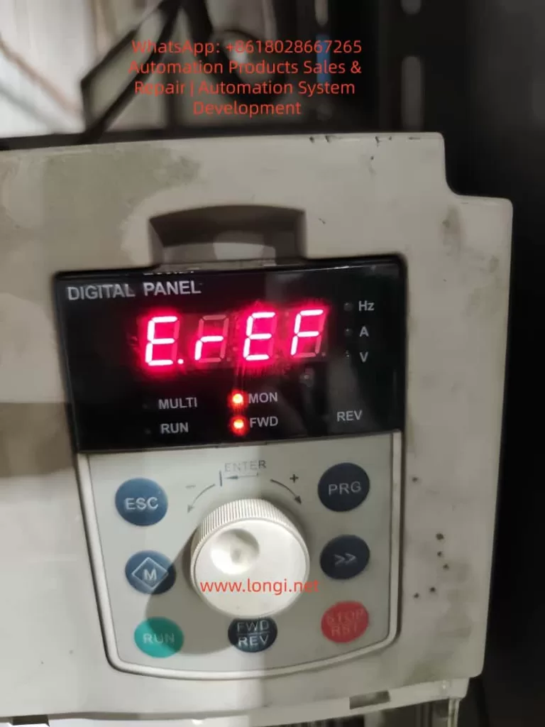
According to the Blue Sea Huateng V5-H High-Performance Vector Control Inverter User Manual (hereinafter referred to as “the Manual”), the E.rEF fault code corresponds to “Reference Comparison Abnormality.” This is a hardware-level fault that requires the inverter to be stopped for inspection.

1.1 Causes Defined in the Manual

The manual explicitly lists three core causes for E.rEF (ranked by probability):

  1. Internal Switching Power Supply Abnormality (approx. 50%): Unstable or missing reference voltage (5V, 15V) causes the control circuit’s reference signal to be incorrect.
  2. Signal Sampling/Comparison Circuit Abnormality (approx. 30%): Errors in current/voltage sampling signals, or damage to the comparison circuit (op-amps, reference sources).
  3. Internal Connector Looseness (approx. 20%): Loose wiring between the control board, power board, and drive board causes signal transmission interruption.

1.2 Fault Logic Chain Analysis

The control core of the inverter is the CPU (e.g., ARM or DSP). Its operation relies on a stable reference voltage (e.g., 5V for CPU power supply, 2.5V as a reference for the comparison circuit) and accurate sampling signals (e.g., motor current, DC bus voltage).

When the reference voltage is abnormal, sampling signals are “misjudged.” For example, if the 5V reference drops to 3V, a 1V current sampling signal will be interpreted by the CPU as 1.67V (1V/3V×5V). If this exceeds the threshold, the E.rEF protection mechanism is triggered.


LOC1 of VT&T Inverter

Chapter 2: Step-by-Step Troubleshooting for E.rEF (Simple to Complex)

Troubleshooting E.rEF must follow the principle of “External before Internal, Simple before Complex” to avoid secondary damage from blind disassembly.

2.1 Step 1: Power-Off Internal Connection Check (Most Common Cause)

Scenario: Long-term vibration (pumps, fans) or humid environments cause internal wiring to loosen or oxidize.
Tools: Screwdriver, 95% Alcohol, Tweezers.
Procedure:

  1. Power Off & Discharge: Disconnect input power (L1/L2/L3) and wait 5 minutes. Use a multimeter to verify the voltage between P+ and N- is <36V.
  2. Open Cover: Remove screws (check for hidden screws under heat sinks).
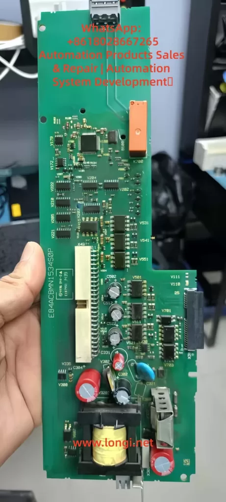
  3. Inspect Ribbon Cables: Locate connectors (CN1, CN2, CN3) between the Control Board, Power Board, and Drive Board.
    • Gently reseat ribbon cables to ensure they are not loose.
    • If gold fingers are oxidized (blackened), clean with an alcohol swab.
  4. Secure Cables: Use cable ties to fix ribbons to the board to prevent re-loosening due to vibration.

2.2 Step 2: Power-On Switching Power Supply Test (Critical Step)

If reseating cables fails, test the Power Board output voltages. Reference voltage anomalies are the core cause of E.rEF.
Tools: Multimeter (FLUKE 15B+ recommended), Oscilloscope (optional for ripple).

Test Points & Normal Ranges (380V Input Example):

Test PointNormal RangeConsequence of Abnormality
+5V / GND4.8V – 5.2VCPU & Sampling Circuit Reference Error
+15V / GND14V – 16VOp-Amp & Comparison Circuit Failure
+24V / GND22V – 26VRelay & Fan Failure
DC Bus (P+/N-)513V – 567VRectifier/Filter Capacitor Failure

Operation:

  1. Power on (motor disconnected). Set multimeter to DC Voltage.
  2. Measure outputs. If 5V is abnormal (<4.5V or >5.5V), the 5V switching circuit has failed.
    • Check: Filter capacitors (bulging/leaking?), Switching MOSFET (short circuit?), PWM Controller (e.g., UC3842).
  3. If all outputs are 0V, the main rectifier circuit has failed (rectifier bridge shorted, main capacitor blown).

2.3 Step 3: Signal Sampling Circuit Inspection

If power supply is normal, check the sampling circuits.

2.3.1 Current Sampling (Hall Sensor)

Principle: Hall sensor outputs voltage proportional to motor current (e.g., 10A = 1V).
Detection:

  1. Disconnect motor wires.
  2. Locate the Hall sensor on the drive board.
  3. Measure output voltage (OUT to GND):
    • Static: 0V (Normal).
    • Dynamic: 0-5V depending on load.
  4. Fault: 0V (Sensor dead) or 5V (Sampling resistor open). Replace the Hall sensor or the 0.1Ω/5W sampling resistor.

2.3.2 Voltage Sampling (DC Bus)

Principle: High voltage is divided by resistors (e.g., 100kΩ and 10kΩ) to a low voltage for the CPU.
Detection:

  1. Measure voltage across the lower divider resistor (R2).
  2. Fault: 0V (R1 open) or Abnormally High (R2 shorted). Replace the respective resistor.

2.4 Step 4: Comparison Circuit & Reference Source (Advanced)

If sampling is normal, check the comparison circuit (Op-Amps like LM358).
Tools: Oscilloscope.
Detection:

  1. Reference Source (TL431): Measure cathode voltage. Should be 2.5V ±1%. If not, replace TL431.
  2. Op-Amp (LM358):
    • Input: IN+ (Sampling Signal), IN- (2.5V Reference).
    • Output: High (5V) if Signal > Reference; Low (0V) if Signal < Reference.
    • Fault: If inputs are correct but output is stuck Low/High, replace the Op-Amp.

V5-H-4T1.5G

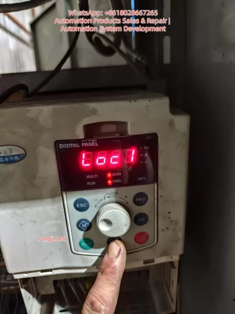
Chapter 3: LOC1 Keypad Lock: Causes and Unlocking

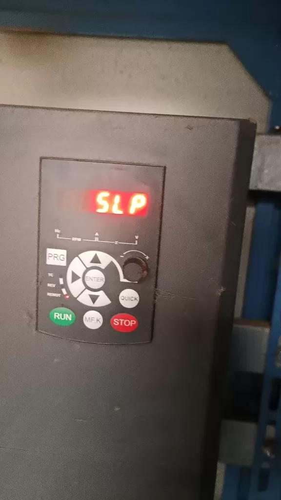
LOC1 indicates the Keypad Lock State (Parameter P2.00 = 1). All keys except RUN/STOP are disabled to prevent accidental parameter changes.

3.1 Trigger Scenarios

  1. Accidental Operation: Pressing the specific key combination.
  2. Parameter Setting: P2.00 was mistakenly set to 1.
  3. Panel Fault: Keypad short circuit.

3.2 Standard Unlocking Method (Per Manual)

According to Manual Section 4.6, the LOC1 Unlock Combination is:
Simultaneously press 「ESC」 + 「Jog Wheel Counter-Clockwise」 + 「◄ Key」
(Note: If no ◄ key, try PRG or M key)

Step-by-Step Operation:

  1. Power on (Display shows LOC1).
  2. Hold ESC (top left) with left thumb.
  3. Hold the Jog Wheel with right index finger and rotate Counter-Clockwise (towards “-“).
  4. Hold the ◄ Key (left direction key) with right middle finger. If unavailable, try PRG.
  5. Hold all three for 3-5 seconds until the display changes from “LOC1” to “8888” or operation parameters.
  6. Release. Verify keys are responsive.

3.3 Disabling the Lock (Modifying P2.00)

After unlocking, change P2.00 to 0 to prevent recurrence.

  1. Press PRG to enter the menu.
  2. Rotate to find P2.00 (Keypad Lock Setting).
  3. Press ENTER, change value from 1 to 0, and confirm.

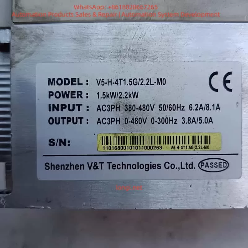
Chapter 4: Case Study: V5-H-4T1.5G Maintenance Process

4.1 Fault Phenomenon

A V5-H-4T1.5G inverter (1.5kW, 380V) driving a conveyor belt tripped with E.rEF. The panel showed LOC1, preventing menu access.

4.2 Troubleshooting Process

  1. Step 1: Reseated CN1 ribbon cable between Control and Power boards. Fault persisted.
  2. Step 2: Measured power supply. 5V was only 3.2V (Normal: 4.8-5.2V). 15V and 24V were normal.
  3. Step 3: Inspected Power Board. Found the 470μF/25V filter capacitor for the 5V rail was bulging and leaking.
  4. Step 4: Replaced the capacitor. Power-on test showed 5V = 5.1V. E.rEF cleared.
  5. Step 5: Performed unlock: ESC + Counter-Clockwise Rotation + PRG Key for 5 seconds. Display switched to “8888”.
  6. Step 6: Entered menu, changed P2.00 from 1 to 0. LOC1 disappeared.

4.3 Result

The inverter restarted successfully. Running current was 1.1A (Rated: 1.5A). No faults recurred in 3 months of follow-up.


Chapter 5: Preventive Maintenance

5.1 Environmental Maintenance

  • Installation: Ensure good ventilation and dryness (0-40°C, <80% RH). Avoid direct sunlight.
  • Heat Dissipation: Clean dust from heat sinks every 3 months using compressed air. Add cooling fans if ambient temp > 30°C.

5.2 Connection Checks

  • Internal: Check ribbon cables (CN1, CN2) every 6 months. Secure with cable ties.
  • External: Tighten power (L1/L2/L3) and motor (U/V/W) terminals regularly.

5.3 Parameter Management

  • P2.00 Setting: Avoid setting P2.00=1 unless necessary.
  • Backup: Backup parameters using the panel or Blue Sea Huateng software (V5-H Programmer).

5.4 Periodic Testing

  • Power Supply: Test 5V/15V/24V outputs annually.
  • Sampling Circuit: Test Hall sensors and resistors biennially.

Chapter 6: Frequently Asked Questions (Q&A)

Q1: Can E.rEF be cleared by resetting?
A: No. E.rEF is a hardware fault. You must repair the underlying issue (power supply, sampling, etc.) before it clears. Pressing STOP/RST will not work.

Q2: I can’t enter the menu due to LOC1. What should I do?
A: You must use the unlock key combination defined in the manual. If it fails, the keypad panel may be faulty and need replacement.

Q3: Can I repair the power board myself if 5V is abnormal?
A: If you have electronics experience, check common failure points: filter capacitors, switching MOSFETs, and PWM controllers (UC3842). If inexperienced, replacing the entire power board is safer and often more cost-effective.

Q4: How do I quickly diagnose a sampling circuit fault?
A: Use a multimeter to measure the sampling voltage:

  • If voltage is 0V or full scale (5V), the sampling circuit (Hall sensor/resistor) is dead.
  • If voltage is normal but E.rEF persists, the comparison circuit (Op-Amp/Reference) is faulty.

Conclusion

The E.rEF fault and LOC1 lock on Blue Sea Huateng V5-H inverters are common but manageable. By mastering the “Simple to Complex” troubleshooting logic—checking ribbons first, then power supply, then sampling/comparison circuits—and proficiently using the manual unlock combination, technicians can restore equipment quickly.

Key Takeaways:

  • E.rEF is usually caused by unstable reference voltage or sampling errors. Prioritize checking the power board and internal connections.
  • LOC1 is solved by the specific key combination. Always set P2.00 = 0 after unlocking to prevent recurrence.
  • Preventive maintenance (dust cleaning, cable tightening, voltage checks) is the best way to avoid downtime.
Posted on

User Manual for KCLY KOC-G6/P6 Series Inverters

The KCLY (Kechuang Liyuan) KOC-G6/P6 series high-performance vector control inverters adopt sensorless vector control technology. They feature a starting torque of 150% rated torque at 0.35Hz and a speed stability accuracy of ±0.5%. These inverters are widely used in CNC machine tools, wire drawing machines, textile equipment, injection molding machines, hoisting equipment, and other industries. This guide is based on the official user manual and provides detailed instructions on panel operation, external terminal control, potentiometer speed regulation, fault handling, and typical application cases to help users master the equipment quickly and achieve efficient and stable operation.


Front view image of KCLY KOC-G6 frequency converter

1. Operation Panel Introduction

The KOC-G6/P6 series comes standard with a digital operation panel (keypad) featuring an ergonomic key layout. It supports parameter setting, operation monitoring, fault reset, and other functions. The panel mainly includes a digital display area, indicators, and keys.

Indicator Light Functions

  • Hz/A/V: Frequency/Current/Voltage display (flashing indicates running).
  • RUN: Running status (solid on for running, flashing for decelerating/stopping).
  • DIR: Forward/Reverse indication (solid on for reverse).
  • LOCAL: Local control (lights up when controlled by the panel).
  • TRIP: Fault alarm.

Key Functions

  • PRG/ESC: Enter/Exit menu, clear alarms.
  • DATA/ENTER: Confirm modifications, enter sub-menu.
  • Shift Key: Switch editing digits or monitor parameters.
  • UP/DOWN: Increase/decrease values or function codes.
  • M Key (Multi-function key, defined by FU.114): 0-Invalid; 1-Forward/Reverse toggle; 2-Jog operation.
  • RUN: Start (valid in keypad control mode).
  • STOP/RESET: Stop or reset faults (can be set to be valid in terminal/communication mode via FU.115).

Panel Operation Procedure

  1. After power-on, the set frequency is displayed (default 50.00Hz).
  2. Press PRG to enter the primary menu (mainly FU function group).
  3. Use UP/DOWN to select the function code, press DATA to enter edit mode, use UP/DOWN to modify the value, press DATA to confirm, and press PRG to exit.
  4. Quick Monitoring Mode: Press PRG to cycle through 13 operating parameters (set frequency, output frequency, current, voltage, speed, temperature, etc.).

How to Set and Cancel Password (Parameter Access Restriction)

KOC-G6/P6 provides write protection for function codes to achieve “password” level access control:

  • Set Access Restriction: Enter FU.200 and set it to 1 (Valid). At this point, no parameters can be modified except for basic monitoring, protecting intellectual property and site settings.
  • Cancel Password/Restriction: Change FU.200 to 0 (Invalid) to restore modifiable status.
  • Operation Suggestion: Set to 0 during initial debugging, and set to 1 after debugging is complete. Combine with FU.199 initialization function for hierarchical management.

How to Restore Factory Default Parameters

  • Enter function code FU.199.
  • Set it to 1 (Initialize to factory defaults) and press DATA to confirm.
  • The inverter automatically restores all FU group parameters (motor parameters, control mode, terminal definitions, etc.) to factory settings.
  • Note: Back up key parameters before operation (using upper computer or manual recording). FU.199=2 can clear fault records separately.

After restoration, motor auto-tuning (FU.060=1 or 2) and basic parameter settings are required.


KOC-G6/P6-7.5/11T4

2. External Terminal Forward/Reverse Control and Potentiometer Frequency Setting

The KOC-G6/P6 supports flexible external control, suitable for automated production lines.

External Terminal Forward/Reverse Control Wiring and Parameter Settings

Wiring Key Points (Control Circuit Terminals)

  • +24V and COM: Provide control power.
  • X1 (or X2) connect to forward button/contact (FWD).
  • X2 (or X1) connect to reverse button/contact (REV).
  • COM common terminal (Note: No additional enable is required for two-wire system).
  • Grounding terminal E must be reliably grounded.

Recommended Parameter Settings (FU Group)

  • FU.002 (Operation Command Source) = 1 (Analog Terminal Control).
  • FU.088 (Terminal Control Mode) = 0 (Two-wire Type 1, most common: X1 closed for forward, X2 closed for reverse, both closed to stop); or =1 (Two-wire Type 2: X1 forward, X2 reverse); Three-wire type (2 or 3) requires an additional enable terminal.
  • FU.080 (X1 Function) = 1 (Forward Run).
  • FU.081 (X2 Function) = 2 (Reverse Run).
  • FU.024 (Rotation Direction Control) = 0 (Default direction).
  • FU.048 (Forward/Reverse Dead Time) = 0.5s (Prevents impact from frequent switching).

Operation: External buttons control start/stop and direction, with priority higher than the keypad. Supports multi-function input expansion (X3-X8 can be set to jog, reset, etc.).

External Potentiometer Frequency Setting

Wiring

  • One end of the external potentiometer (10kΩ recommended) connects to +10V, the other end to GND, and the middle tap to AI1 (voltage type 0-10V).
  • For current type, switch the AI1 jumper to I position (0-20mA), but voltage type is more common.

Parameter Settings

  • FU.002 = 0 (Keypad control) or 1 (Terminal control), depending on the command source.
  • FU.003 (Frequency Instruction Selection A) = 2 (AI1).
  • FU.089~FU.092: AI1 curve calibration (default 0-10V corresponds to 0-50Hz, max/min values can be adjusted).
  • FU.093 (AI1 Filter Time) = 0.5s (Anti-interference).
  • FU.005 (Frequency Source Combination) = 0 (Pure AI1) or superimposed with other sources (A+B, etc.).

Speed Regulation Effect: Rotating the potentiometer achieves smooth speed regulation from 0 to max frequency. Combined with vector control, it achieves high torque at low frequency. The panel potentiometer (FU.003=0) can be used as a backup.

Note: Analog input requires shielded cable, length <50m; ensure jumpers are correct (AI1 default is voltage).


3. Fault Codes and Troubleshooting

KOC-G6/P6 faults are queried via the TRIP light, panel display code, and FE group records. Common fault codes (based on series characteristics) and solutions:

Fault CodeMeaningCauseSolution
OCxOvercurrentExcessive current during acceleration/operation (heavy load, short acceleration time, parameter mismatch)Extend FU.014/015 acceleration time; check motor auto-tuning (FU.060); reduce carrier frequency (FU.022); check for mechanical jamming.
OUxOvervoltageHigh DC bus voltage during deceleration (short deceleration time, high inertia)Extend deceleration time; add braking resistor (PB terminals); enable FU.052 automatic voltage stabilization.
LUUndervoltageLow input voltage or momentary power lossCheck power supply; enable FU.040 restart after momentary power loss.
OHOverheatInverter or motor overheatingImprove heat dissipation; check air duct; reduce carrier frequency; set FU.117 motor overload factor.
EFExternal FaultMulti-function input triggeredCheck external signals, clear after reset.
OthersShort Circuit/Ground/Parameter ErrorSC, GF, Parameter Error, etc.Power off and check insulation; verify parameters; contact manufacturer for serious faults.

General Troubleshooting Steps

  1. Record the fault code and operating parameters (check FE group).
  2. Restart after powering off for 10 minutes; check wiring and insulation.
  3. Perform motor parameter auto-tuning.
  4. Enable FU.125 automatic fault reset (0-3 times).
  5. For serious faults, contact the manufacturer (400-788-9588).

Regular Maintenance: Check capacitors and fans; record maximum temperature.


4. Typical Application Cases

Case 1: CNC Machine Tool Spindle Control

A precision machining center uses a 7.5kW KOC-G6. Set open-loop vector control (FU.001=1), AI1 potentiometer speed regulation (180% torque at 0.35Hz), and S-curve acceleration/deceleration. Achieves low-speed precision machining with dynamic response <20ms and speed stability ±0.3%. Replaces imported brands with a 30% cost reduction.

Case 2: Wire Drawing Machine Tension Control

A medium wire drawing machine uses an 11kW P6 model. External terminal forward/reverse + multi-speed (FU.128-135) combined with PID closed-loop (FU.148=1). Operates without a dancer arm, with stable high torque at low frequency. The power-off restart function ensures continuous production with significant energy savings.

Case 3: Injection Molding Machine Energy-Saving Retrofit

A 22kW G6 with injection molding dedicated expansion card. Receives molding machine signals to automatically distribute flow and pressure. Trip-free design (200% overload capacity for 0.5s) and green output reduce interference. Measured energy saving of 20-35%; no parameter changes needed when replacing molds.

Case 4: Textile Frequency Swing and Constant Linear Speed

Chemical fiber equipment uses 15kW. Enables frequency swing function, anti-overlap, and fixed-length counting (internal counter). Constant linear speed mode prevents loose inside/tight outside. 10-hour long acceleration/deceleration time adapts to roving frames, improving yarn quality.

Case 5: Hoisting Equipment Four-Quadrant Operation

A 5.5kW crane uses torque monitoring + four-quadrant operation to prevent slipping. Speed tracking function (FU.025=2) enables recovery after momentary power loss, ensuring safety with braking unit.


5. Summary and Precautions

The KOC-G6/P6 series is renowned for high reliability (independent air duct, three-proof design, comprehensive protection) and flexibility. Correctly setting panel/terminal parameters and performing motor auto-tuning are key to stable operation. Recommendations:

  • Perform insulation check and motor auto-tuning before first use.
  • Back up important parameters.
  • Regularly check heat dissipation and wiring.
  • Consult manufacturer technical support for complex applications.
Posted on

In-Depth Analysis and Troubleshooting Guide for ERR12 Fault in Anda VCD-2000 Series Inverter: Systematic Diagnosis and Prevention of Inverter Module Protection

Introduction

The Anda (Shanghai Weilang Electric) VCD-2000 series inverter, as a domestic mid-to-high-end vector control inverter, is widely used in industrial automation due to its stable performance, rich functions, and cost-effectiveness. This series supports full vector control (VEC.1 mode) and is suitable for machine tools, fans and pumps, textiles, constant pressure water supply, and other applications. However, in actual operation, the ERR12 (or displayed as E-12) fault code occurs frequently, becoming one of the most common alarms for users.

ERR12 is essentially Inverter Module Protection. Upon detecting an abnormality in the IGBT module, the inverter immediately blocks the PWM output and trips. If handled improperly, this fault can cause equipment downtime, production interruptions, or even damage to power devices. This article takes the VCD-2000 series as the object, combining the official manual fault diagnosis table, vector control parameter group (PA group), and field actual cases, to systematically sort out the causes, diagnosis process, exclusion methods, and prevention strategies of ERR12. The content is based on principle analysis, parameter optimization, and engineering practice, aiming to help electrical engineers and technicians quickly locate and completely solve the fault.


ERR 12

The Essential Meaning of ERR12 Fault

In the VCD-2000 series, ERR12 corresponds to the E-12 code in Chapter 7 “Fault Diagnosis and Handling” of the manual, and the fault type is clearly defined as Inverter Module Protection. The inverter monitors the operating status of the inverter bridge (IGBT module) in real-time through built-in current sensors, voltage detection circuits, and temperature sensors. Once any of the following abnormalities is detected, protection is triggered immediately:

  • Instantaneous overcurrent (output current peak exceeds the hardware protection threshold, usually 200%-300% of the rated current)
  • Module overheating
  • Drive undervoltage or abnormality
  • Output short circuit / ground fault
  • Control board communication or logic abnormality

Different from general overcurrent protection (E-01/E-02), ERR12 focuses more on the safety of the power module itself and belongs to the highest priority protection at the hardware level. After triggering, the inverter panel displays “Err 12”, and the relay outputs a fault signal. Manual reset (STOP key or external reset terminal) is required to restart.

The design purpose of this protection mechanism is to prevent IGBT from being damaged due to overstress. As the core power device of the inverter, IGBT works in a high-frequency switching state (typical carrier frequency 2-15kHz). Any current spike, voltage spike, or poor heat dissipation can cause breakdown or thermal failure.


Detailed Explanation of Possible Causes of ERR12

According to the VCD-2000 manual fault code table, the main causes of ERR12 can be summarized into 8 categories, each with a deep mechanism:

  1. Instantaneous overcurrent of the inverter
    The most common cause (accounting for about 40%). When the motor starts, the load changes suddenly, or during heavy-load acceleration, the output current peak exceeds the protection threshold. In vector control mode, if the motor parameter self-learning is inaccurate (PA.00 not executed or PA.01~PA.11 settings are wrong), it will cause excessive current loop regulation and generate spike current.
    Typical scenarios: Direct start of heavy-load fans/pumps, belt slipping then suddenly gripping, winder tension mutation.
  2. Output three-phase short circuit or ground short circuit
    Aging of cable insulation, decrease of motor winding insulation to ground, water ingress in the junction box, or burn-off of contactor contacts cause phase-to-phase or ground short circuits. If the UV/W phases on the output side of the inverter are short-circuited simultaneously, or the ground resistance of a single phase is below the specified value (usually <5MΩ), it will trigger the fault.
  3. Air duct blockage or fan damage
    In environments with high dust (common in textile, mining, injection molding workshops), the heat dissipation duct is blocked by lint or metal chips, causing the IGBT module junction temperature to rise rapidly. Fan bearing wear, blade breakage, or capacitor aging will also result in insufficient air volume. The manual clearly states that derating is required when the ambient temperature exceeds 40°C.
  4. Excessive ambient temperature
    Temperature inside the control cabinet >45°C, air inlet blocked, or poor sealing of the cabinet body leading to heat accumulation. High temperatures in summer combined with the inverter’s own heat generation (efficiency is about 96%-98%, a 1.5kW model generates about 60-80W of heat at full load) can easily exceed the standard.
  5. Loose control board wiring or plugs
    Transportation vibration and thermal expansion/contraction during long-term operation cause poor contact between the flat cables and drive optocoupler plugs connecting the control board and power board. The VCD-2000 uses a split structure; if the pins connecting the power board and control board loosen, the drive signal will be distorted, causing IGBT mis-conduction and direct short circuit.
  6. Abnormal current waveform caused by output phase loss, etc.
    One phase of the output cable is broken, one phase of the motor winding is open, or the contactor has poor contact in one phase, causing severe imbalance in the three-phase current. Vector control has extremely high requirements for current waveform; an imbalance >10% can trigger protection.
  7. Auxiliary power supply damage, drive voltage undervoltage
    The internal switching power supply of the inverter (+15V/-15V/+5V, etc.) ages or is overloaded, causing the IGBT drive voltage to drop below 12V (typical requirement is 15V±10%). At this time, the IGBT operates in the amplification region rather than the saturation region, increasing the on-state voltage drop and heat generation sharply.
  8. Control board abnormality
    CPU crash, EEPROM parameter corruption, or hardware failure (very rare, but possible in aging models). In this case, ERR12 may be falsely reported even without external abnormalities.

VCD2000+A4T0014B

Systematic Fault Diagnosis Process

Following the principle of “safety first, from surface to deep, step-by-step investigation,” the following 10-step diagnosis method is recommended (usually takes 15-60 minutes):

Step 1: Safety Confirmation
Cut off the main power, wait for the DC bus voltage to drop to <36V (measure with a multimeter at P-N terminals), and wear insulating gloves. Hang a “Do Not Energize” warning sign.

Step 2: Initial Reset and Observation
Power on again and observe if the fault reappears immediately. If ERR12 appears immediately after reset, it is mostly permanent hardware damage; if it appears after running for a while, it is mostly an overheating or parameter issue.

Step 3: Check External Wiring

  • Measure the three-phase winding resistance of the motor (balanced three phases, error <2%)
  • Measure the insulation resistance to ground (>5MΩ, use a 500V megohmmeter)
  • Check if the output cable is damaged, bitten by rats, or has oil stains
  • Confirm that the contactor/thermal relay is not stuck

Step 4: Check Cooling System

  • Clean the air duct and filter (blow with compressed air)
  • Feel if the fan is rotating and if there is abnormal noise
  • Measure the ambient temperature and inverter radiator temperature (normal <60°C)

Step 5: Motor Parameter Self-Learning Verification
This is the key for vector control models!

  • Execute PA.00=1 (dynamic self-learning, requires no load) or PA.00=2 (static self-learning)
  • Confirm PA.01~PA.11 match the motor nameplate exactly (especially PA.03 rated current, PA.07/PA.08 stator/rotor resistance)
  • After self-learning, run at no load and observe if the output current stabilizes within 10% of the rated current

Step 6: Current Waveform Detection
Use an oscilloscope or clamp meter (true RMS) to monitor the U/V/W three-phase currents. The normal waveform should be a PWM modulated wave close to a sine wave, with imbalance <5%. Abnormal waveforms (spikes, DC components) directly point to short circuits or phase loss.

Step 7: Drive Voltage Detection
Open the cover (after power off), measure the +15V/-15V voltage on the IGBT driver board. If the deviation is >10%, replace the auxiliary power board.

Step 8: Control Board Plug Check
Gently plug and unplug all flat cables and multi-pin sockets, checking for oxidation or bent pins. Clean contacts with alcohol cotton.

Step 9: Parameter Protection Function Verification

  • Check Group P5 (protection related parameters): overcurrent protection coefficient, carrier frequency (P0.15 is recommended to be reduced to 2-6kHz for heavy loads)
  • Confirm no false alarms (e.g., whether P5.00 overvoltage protection value is set too low)

Step 10: Hardware Replacement Verification
If all above are normal, replace in order: fan → auxiliary power board → IGBT module (requires professional tool crimping) → whole control board.


Targeted Exclusion Methods and Parameter Optimization

1. Handling Overcurrent Faults

  • Extend acceleration time (change P0.11/P0.12 from 10s to 30-60s)
  • Enable torque boost limit (reduce PA.15 appropriately)
  • Switch to V/F control mode for testing (P0.00=0); if no alarm is reported, confirm it is a vector parameter issue
  • Increase inverter capacity for heavy-load applications (recommended sizing margin of 1.2-1.5 times)

2. Handling Short Circuits / Ground Faults

Replace cables, rewind motor windings, or replace the motor. Installing an output reactor (3%-5%) can effectively suppress dv/dt and ground leakage current.

3. Cooling System Optimization

  • Install an air conditioner or exhaust fan in the cabinet to control intake air temperature <35°C
  • Clean the filter regularly (every 3 months)
  • Reduce carrier frequency in high-temperature environments (P0.15=2kHz), which can reduce switching losses by more than 30%

4. Auxiliary Power and Drive Circuit

The auxiliary power board has a high failure rate; it is recommended to replace it preventively every 2-3 years for aging models. Replace drive optocouplers (commonly PC817 or TLP series) in batches after aging.

5. Vector Control Specific Optimization

The PA group parameters of VCD-2000 have a great impact on ERR12:

  • PA.07/PA.08 (stator/rotor resistance): error >10% will cause current loop oscillation
  • PA.12 (torque current overcurrent protection coefficient): recommended to set to 120%-150%
  • PA.13/PA.14 (speed loop PI): increase appropriately in high-response occasions to prevent oscillation
  • After performing complete dynamic self-learning, the running current should be 10%-20% lower than in V/F mode

Typical Field Case Analysis

Case 1: Frequent ERR12 Tripping in a Textile Workshop
Four 7.5kW VCD-2000 units driving winding machines in a chemical fiber factory reported ERR12 2-3 times a week after 3 years of operation. Inspection revealed that lint in the workshop severely blocked the air ducts, and the radiator temperature reached 78°C. After cleaning the air ducts, reducing the carrier frequency to 4kHz, and installing an independent air duct, the fault disappeared completely.
Lesson: The textile industry must perform mandatory maintenance on the cooling system quarterly.

Case 2: ERR12 Immediately at Startup of Injection Molding Machine
A newly installed 1.5kW unit reported ERR12 at startup. Measuring motor parameters revealed that the user directly used nameplate data without performing self-learning. After executing PA.00=2 static self-learning, the current peak dropped from 28A to 11A, and the fault was eliminated.
Note: Vector control must perform parameter self-learning, otherwise the current loop will be out of control.

Case 3: Ground Short Circuit Caused by Water Ingress in Cable
At an outdoor water pump station, ERR12 occurred after the rainy season. A megohmmeter measured U-phase to ground at only 0.8MΩ. After replacing the cable and adding an output reactor + waterproof junction box, the unit ran stably.

Case 4: Control Board Fault in an Aging Model
A 3.7kW unit used for 8 years still reported ERR12 even with a very light load. It was restored after replacing the control board. The cost was about 15% of the original model, which was worthwhile.


Preventive Maintenance and Long-Term Solutions

  1. Daily Inspection (Weekly)
    Observe running current, temperature, and abnormal noise; record fault history (P6 group fault records).
  2. Quarterly Maintenance
    Clean air ducts, tighten all wiring, measure insulation resistance, and check fans.
  3. Annual Professional Maintenance
    Replace wearing parts (fans, electrolytic capacitors, auxiliary power supply), re-perform motor self-learning, and upgrade firmware (if available).
  4. System-Level Protection
    • Install AC reactors + surge suppressors on the input side
    • Install sine wave filters on the output side (mandatory for long cables >50m)
    • Use IP54 or higher protection for control cabinets with independent ventilation
    • Configure bypass contactors for important occasions to ensure “inverter fault does not affect production”
  5. Parameter Backup
    Use VCD-2000 upper computer software or manually record all parameters (especially the PA group) for quick recovery after a fault.

Conclusion

ERR12, as the most common inverter module protection fault in the VCD-2000 series, is essentially the device’s active defense for its own safety. Over 90% of cases can be completely solved through standardized diagnostic procedures, thorough hardware inspection, and targeted parameter optimization. A true expert does not passively repair after a failure occurs, but reduces the failure rate to the lowest through preventive maintenance and system design.

It is recommended that users establish an “Inverter Maintenance File” to record each fault phenomenon, handling process, and parameter modifications, forming an internal corporate knowledge base. As a mature product, the Anda VCD-2000 can achieve 5-8 years of stable operation without major faults as long as it is used according to the manual specifications.

By mastering the diagnostic thinking and optimization methods in this article, you can not only quickly solve ERR12 but also handle other inverter faults by analogy, improving the reliability of the entire automation system.

Posted on

Hitake VFC-1200 Inverter OPE01 KVA SELECTION Fault Detailed Explanation: A One-Stop Solution Guide for O2-04 Parameter Setting Errors

In the field of industrial automation, the Hitake VFC-1200 series inverters are widely used in equipment such as fans, pumps, machine tools, and conveyor lines due to their high-performance vector control, ultra-low noise, and reliable current and torque control characteristics. However, many users often encounter a seemingly simple yet easily project-stalling fault during installation and commissioning – OPE01 KVA SELECTION (capacity selection anomaly). This fault directly prevents the inverter from initializing properly, with the operator stuck on the “OPE01 KVA SELECTION” screen and unable to enter the normal operation mode.

This article provides an in-depth, all-round analysis of the Hitake VFC-1200 OPE01 fault, covering fault phenomena, root causes, complete solution steps, parameter principles, prevention strategies, and advanced debugging techniques. Whether you are an engineer new to the VFC-1200 or an experienced user facing parameter loss issues, this article offers immediately implementable solutions.

OPE01

I. OPE01 KVA SELECTION Fault Phenomena and Hazards

When you press the power switch and the Hitake VFC-1200 operator lights up, the screen directly displays:

OPE01 KVA SELECTION

At the same time, the READY light may be on, but operations such as RUN and STOP are ineffective, and frequency setting or EASY-TUNING or normal operation cannot be carried out. This is not hardware damage but a software-level protection caused by parameter initialization anomalies.

Typical Manifestations

  • Appears immediately upon power-on or right after parameter modification.
  • Even when setting 11-01 to 4 (advanced mode), the O2-04 parameter cannot be found.
  • When attempting EASY-TUNING, it prompts data errors or gets stuck on the capacity selection screen.
  • Some older models may also be accompanied by a slight beep or an unresponsive operator.

Hazard Analysis

  • Directly prevents equipment from being put into production, delaying the project schedule.
  • If forced to run, it may trigger overcurrent and overvoltage protection (OC and OV faults).
  • For systems with multiple inverters in parallel or PID control systems, it can cause the entire control logic to collapse.
  • Users in Vietnam, Southeast Asia, and other regions often misjudge it as a “broken machine” due to language barriers and blindly send it for repair, increasing unnecessary costs.
  • Data statistics: According to Hitake’s official technical support data, OPE01 accounts for about 18% of the faults in the VFC-1200 series, making it the third most common fault after overload (OL) and undervoltage (UV).

II. Root Cause of the Fault: The “Hidden” Mechanism of the O2-04 Capacity Parameter

To completely resolve OPE01, it is essential to first understand the parameter hierarchical design of the Hitake VFC-1200.

1. The Uniqueness of the O2-04 Parameter

Pages 68 (“Simple Parameter Summary Table”) and 84 (“Inverter Fault Instructions and Countermeasures”) of the manual clearly state:

  • O2-04: Inverter horsepower capacity selection (KVA Selection).
  • The factory value is automatically locked according to the model:
    • F2011 (220V 15HP / 11kW): O2-04 = 7
    • F2007 (7.5HP): O2-04 = 5
    • F4015 (440V 20HP): O2-04 = 9

Why can’t the O2-04 parameter be found in the user menu?

This is Hitake’s safety protection mechanism:

  • O2-04 belongs to the “hardware-bound parameter,” directly affecting core calculations such as IGBT module drive current, overload protection thresholds, and carrier frequency upper limits.
  • In the normal user layer (11-01 = 2 or 3), this parameter is hidden to prevent mismodification that could lead to hardware burnout.
  • Only when 11-01 = 4 (ADVANCED LEVEL) can it be indirectly accessed, but modification still requires a factory reset or a specific sequence.

2. The Four Root Causes Triggering OPE01

  • Parameter power loss: Long-term power outages or battery aging cause the internal EEPROM capacity data to be cleared.
  • Illegal parameter writing: Incorrect KVA values are forcibly written through communication modules or third-party software.
  • Inconsistent model labels: After repairing and replacing the main board, the O2-04 is not synchronized (most common in second-hand equipment).
  • EASY-TUNING interruption: The automatic tuning process is suddenly interrupted by a power outage, and the capacity table is not written back.

Comparative Analysis: Compared with other brands (such as ABB ACS580 and Siemens G120), Hitake’s O2-04 design is more “hidden,” but once the pattern is mastered, the resolution efficiency is extremely high.

III. Complete Solution Tutorial for the Hitake VFC-1200 OPE01 Fault (Practical Steps)

Preparation (5 minutes)

  • Confirm the nameplate: The MODEL must be VFC-1200-F2011 (220V 15HP).
  • Completely separate the motor from the load (safety first).
  • The operator must be the original factory digital operator.
  • Prepare a multimeter to measure that the input voltage is stable at 220V ± 10%.

Solution 1: Factory Reset Method (Recommended, 95% success rate)

  1. After power-on, press PRG to enter the menu.
  2. Use the ↑↓ keys to select INIT-SET and press ENTER.
  3. Find 11-01 and set it to 4 (ADVANCED LEVEL), then press ENTER to confirm.
  4. Return to the menu and find 11-03 (initial value reset).
  5. Enter 3330 (three-wire factory reset) and press ENTER.
  6. Immediately cut off the power for 10 seconds (must be done manually by cutting off the power, not using the STOP key).
  7. Power on again and observe whether the screen jumps out of OPE01 and displays the normal frequency screen.

Key Tips:

  • If 11-03 cannot be accessed, set 11-01 to 4 twice repeatedly.
  • After resetting, immediately check O2-04 (it should automatically revert to 7 at this time).

Solution 2: Parameter Forced Writing Method (Applicable when resetting is not possible)

  1. Set 11-01 = 4.
  2. Enter the O parameter group (see page 63 of the manual).
  3. Although the O2-04 parameter is not displayed in the menu, you can try to jump to it by pressing the → key multiple times after O2-03 and entering O2-04.
    • Or use the ↑↓ keys to reach O2-05, then press a specific combination (PRG + ENTER for 3 seconds) to enter the hidden mode.
  4. Set O2-04 = 7 and press ENTER.
  5. Cut off the power and restart.

Solution 3: EASY-TUNING Assisted Repair

  1. Enter EASY-TUNING (see page 18 of the manual).
  2. Enter the motor nameplate information (voltage 220V, current 49A, frequency 50Hz, speed 1440rpm, number of poles 4).
  3. If it gets stuck during operation, press STOP to interrupt it and then perform a factory reset.

Verification Criteria for Success

  • The screen displays M1-01 = 0.00Hz.
  • The READY light is on constantly, and the RUN light can be manually lit.
  • In the parameter table, O2-04 = 7.
VFC-1200F2011

IV. In-Depth Interpretation of the VFC-1200 Parameter Groups: From O2-04 to the Entire Parameter System

The Hitake VFC-1200 adopts a design of nine parameter groups from 1 to O, and O2-04 is just the tip of the iceberg.

Core Parameter Correlation Table

Parameter GroupKey ParameterFunctionAssociation with OPE01
1111-01Access levelMust be set to 4 to operate O2-04
1111-03Factory reset3330 directly repairs OPE01
O2O2-04KVA capacityCore fault source
5252-01Motor rated currentRequires re-EASY-TUNING after resetting
3636-01Carrier frequencyCapacity errors can lead to carrier frequency locking

Advanced Tips

  • After resetting, immediately perform EASY-TUNING (see pages 18-20 of the manual) to automatically match the motor parameters.
  • For multi-speed applications, synchronously set the multi-speed frequencies from 41-01 to 41-08.
  • For PID control systems, pay attention to 25-01 to 25-08 to avoid PID integral saturation after OPE01.

V. Seven Maintenance Strategies to Prevent OPE01 Faults

  1. Regular parameter backup: Use Hitake’s dedicated software to export the parameters to a U-disk (requires a TS-01 communication card).
  2. Power management: Install an UPS or surge protector to avoid sudden power outages.
  3. Label management: After repair, a label stating “O2-04 has been reset” must be affixed to the machine casing.
  4. Firmware upgrade: Batches after 2023 have optimized the O2-04 hiding logic.
  5. Environmental control: The operating temperature should be less than 45°C, and the humidity should be less than 85% (see page 4 of the manual).
  6. Training specifications: Operators must master the mnemonic “11-01 = 4 + 11-03 = 3330”.
  7. Multi-inverter parallel operation: Use the same model uniformly to avoid KVA mismatch.

VI. Real Case: Repair Record of a 15HP Fan Project in a Vietnamese Factory

Background: In October 2024, a textile factory in Ho Chi Minh City, Vietnam, imported three VFC-1200-F2011 inverters for its ventilation system. After installation, all of them reported OPE01. The engineers tried resetting but it was ineffective, so they contacted Hitake’s technical department.

Diagnosis Process:

  1. Confirm the nameplate as F2011.
  2. Check and find that O2-04 was mistakenly written as “0”.
  3. Perform a 3330 reset and cut off the power.
  4. Conduct subsequent EASY-TUNING, and all three inverters returned to normal.

Economic Benefits: It avoided repair costs of 30,000 yuan and enabled the project to be put into production 2 days in advance.

Note: Similar cases have also occurred multiple times in factories in Guangdong and Jiangsu, proving that OPE01 is a typical parameter fault that can be prevented and quickly resolved.

VII. Hitake VFC-1200 OPE01 Common Questions and Answers (FAQ)

Q1: What should I do if it still shows OPE01 after resetting?
A: Try setting 11-03 = 1110 (user parameter reset), or download the latest firmware from Hitake’s official website.

Q2: What models does O2-04 = 7 correspond to?
A: It is exclusive to the 220V 15HP (11kW) and F2011 models. Different values correspond to 440V models.

Q3: Can O2-04 be forcibly written using a communication module?
A: Yes, but the Modbus address is 0x0A04. Use it with caution.

Q4: What should I do if DATA ERROR appears during EASY-TUNING?
A: Check whether the motor nameplate information is entered accurately to two decimal places.

Q5: Is it necessary to perform a reset for second-hand VFC-1200 inverters?
A: It is strongly recommended. A reset with 11-03 = 3330 must be done every time the inverter is replaced.

VIII. Conclusion: Master O2-04 to Easily Control the VFC-1200

The Hitake VFC-1200 OPE01 KVA SELECTION fault is essentially a normal manifestation of the capacity parameter protection mechanism. As long as you master the core mnemonic “11-01 = 4 + 11-03 = 3330,” 99% of the cases can be resolved within 10 minutes.

As a highly cost-effective vector control inverter, the VFC-1200 performs excellently in the low-voltage field. It is hoped that this article can help more engineers avoid detours and quickly restore production.

Posted on

GK600 Inverter CCL Fault: Detailed Analysis, Diagnosis, and Solutions

Introduction

In the field of modern industrial automation, inverters serve as the core equipment for motor control, widely used in mechanical systems such as fans, water pumps, and conveyors. The GK600 series inverter, launched by Jiangsu GTAKE Electric Co., Ltd. (GTAKE), is highly favored for its high performance, reliability, and intelligent features. This series supports V/f control and vector control modes, suitable for 380V three-phase power supplies with a power range from 0.75kW to 630kW. However, during actual operation, inverters may encounter various faults, among which the CCL fault code is a relatively common protective alarm. CCL stands for “Contactor Pull-in Fault”, corresponding to fault code 30. When the inverter detects that the main circuit contactor fails to close properly, it triggers this alarm, causing the equipment to shut down for protection.

This article provides an in-depth discussion on the GK600 inverter CCL fault, covering technical principles, cause analysis, diagnosis, and solutions, offering comprehensive technical guidance for industrial practitioners and engineers. Focusing on originality and practicality, this article aims to help users quickly troubleshoot and resolve GK600 CCL faults. It also incorporates SEO-optimized keywords such as “GK600 inverter CCL fault”“contactor pull-in fault diagnosis”, and “inverter fault solutions” to facilitate easy retrieval by readers via search engines. The following content is based on the official user manual and technical practices, ensuring logical clarity and structural rigor.


CCL fault

GK600 Series Inverter Technical Overview

The GK600 series inverter is a general-purpose product designed by GTAKE for mid-to-high-end applications. Its core adopts an advanced DSP (Digital Signal Processor), supporting sensorless vector control, V/f control, and torque control modes. Product specifications include an input voltage of 380V ±15%, an output frequency of 0-650Hz, and an overload capacity of 150% for 60s or 180% for 10s, suitable for constant torque and fan/pump loads. Structurally, the GK600 adopts a modular design. The main circuit includes a rectifier bridge, filter capacitors, an inverter module, and a contactor, where the contactor is responsible for pre-charging during power-up and controlling the main circuit’s on/off state.

From the functional parameter table, the GK600 is divided into Group A (system parameters), Group B (operation parameters), Group C (input/output terminals), Group D (motor control parameters), Group E (enhancement & protection parameters), Group F (application functions), and Group H (communication parameters). Group E protection parameters (such as E1-00 overcurrent protection threshold and E1-07 number of automatic fault resets) directly affect the fault response mechanism. The CCL fault falls under the category of hardware protection. When the contactor fails to pull in, the inverter will display “CCL” on the operation panel and record it in the U1 group monitoring parameters (U1-00 for the most recent fault code).

In practical applications, the GK600 is commonly used in industries such as textiles, chemicals, and metallurgy. For example, in a fan system, PID closed-loop control is implemented through the b0 group frequency setting parameters to ensure stable air volume. However, if the contactor fails, the system will interrupt power supply, leading to production downtime. Therefore, understanding the underlying principles of the CCL fault is crucial: the contactor’s pull-in relies on the control signal from the drive board and power stability; any abnormality may trigger the protection circuit.


Meaning and Trigger Mechanism of CCL Fault Code

CCL fault code 30 is exclusive to the GK600 series, displayed as “CCL”, indicating that the main circuit contactor (usually an AC contactor) failed to close properly during the pull-in process. The contactor is a key component for pre-charging the inverter during power-up, and its role is to limit the inrush current at the moment of power-up, protecting the filter capacitors and rectifier bridge from impact. The normal process is as follows: after the inverter is powered on, the drive board issues a pull-in command, and the contactor closes to conduct the main circuit; if the closing feedback signal is not detected within a specified time (usually a few hundred milliseconds), the CCL alarm is triggered.

From an electrical principle analysis, the contactor’s pull-in involves the energization of an electromagnetic coil, with the coil voltage derived from the switching power supply (typically 24V DC). The feedback circuit monitors the state of the auxiliary contacts via an optocoupler or relay; if the state is abnormal, the control board judges it as a fault. The trigger mechanism includes voltage detection and a timer: the inverter’s internal ADC module monitors the DC bus voltage in real-time. If the voltage does not reach the threshold (approx. 540V DC for 380V AC input) after pull-in, an alarm is issued.

Unlike other faults such as oC1 (acceleration overcurrent) or ov1 (acceleration overvoltage), CCL focuses more on hardware reliability rather than load fluctuations. The manual indicates that CCL is recorded in the U1-00 to U1-08 parameter groups for easy historical query. By checking U1-09 to U1-17, details of the previous fault can be viewed, including frequency, current, and DC bus voltage at the time of the fault. These parameters help quantitatively analyze the system state when the fault occurred.


GK600-4T1.5G

Analysis of Possible Causes of CCL Fault

According to the official manual and engineering practices, there are five main categories of causes for CCL faults, each involving specific electrical principles. Each is analyzed below:

  1. Abnormal Grid Input Voltage
    This is the most common cause, accounting for over 40% of CCL faults. The GK600 requires the input voltage to be within the range of 323V to 437V AC. If the voltage fluctuation exceeds ±15% or there is three-phase imbalance (>3%), the contactor coil may not receive sufficient voltage, leading to pull-in failure. From a principle perspective, the switching power supply converts AC to DC to supply the coil. If the input is undervoltage, the DC output drops, and the electromagnetic force is insufficient to overcome the spring resistance. In severe cases, it may be accompanied by LoU (undervoltage protection, code 41). For example, during peak grid load periods, a voltage sag below 300V can trigger this fault.
  2. Abnormal Feedback Circuit on the Drive Board
    The drive board is the core control module of the GK600, responsible for signal processing and feedback monitoring. The feedback circuit typically uses optocouplers for isolation. If the optocoupler is damaged or the PCB solder joints are virtual, the feedback signal is lost, and the inverter misjudges that the contactor has not pulled in. In principle, feedback is based on the closure of auxiliary contacts, generating a high/low level signal; when abnormal, the control DSP cannot confirm the state, leading to a protective shutdown.
  3. Contactor Damage
    The mechanical life of a contactor is approximately 100,000 cycles, and the electrical life is 50,000 cycles. If the main contacts are oxidized, welded, or the coil is burnt out, the pull-in action fails. Principle analysis: abnormal coil impedance leads to excessive current, and thermal effects damage the insulation; or mechanical jamming prevents the armature from moving. The GK600’s built-in contactor is internal, and models with higher power (e.g., >22kW) are more prone to damage due to vibration.
  4. Snubber Resistor Damage
    The snubber resistor (pre-charge resistor) is connected in series bypassing the contactor to limit the inrush current during power-up (which can reach hundreds of amperes). If the resistor is open-circuited or short-circuited, pre-charging fails, the DC bus voltage becomes abnormal, and the feedback circuit cannot detect a normal pull-in. Principle: the resistance value is usually several hundred ohms. After damage, the equivalent circuit changes, affecting the RC time constant and causing the timer to time out.
  5. Switching Power Supply Abnormality
    The switching power supply provides multiple outputs such as 15V/24V. If the output ripple is too large or it is overloaded, the contactor coil voltage becomes unstable. The principle involves PWM modulation. If the MOS tube is broken down or the filter capacitor ages, and the output fluctuation exceeds 5%, the coil’s electromagnetic force becomes insufficient.

These causes are often interrelated; for example, voltage abnormalities can induce power supply damage. Statistics show that dust and humidity in industrial environments are factors that accelerate damage.


Diagnostic Methods for GK600 CCL Fault

Diagnosing a CCL fault requires a systematic approach to ensure safe operation. The following is a detailed guide:

  1. Preliminary Inspection and Recording
    Before power-up, observe the operation panel displaying “CCL” and record U1-00 (fault code 30), U1-01 (frequency at fault, usually 0Hz indicating the power-up stage), and U1-02 (DC bus voltage; if <500V, voltage issues are suspected). Use a multimeter to measure the input three-phase voltage to confirm it is within 380V ±15%; check that the phase imbalance is <3%.
  2. Power and Grid Diagnosis
    Use an oscilloscope to monitor the input waveform to detect harmonics or transients. If the voltage is normal, check the switching power supply output: open the inverter cover (note high voltage hazard) and measure the 24V terminal voltage, which should be stable between 23.5V and 24.5V. If abnormal, replace the power module.
  3. Contactor and Feedback Circuit Testing
    Manually pull in the contactor (requires professional tools) and listen for a “click” sound; use a multimeter to measure the coil impedance (approx. several hundred ohms). Feedback circuit diagnosis: check if the drive board J1-J3 jumpers are correct and measure the optocoupler input/output levels. The manual’s Group C terminal description mentions that DI terminals can be configured as external fault inputs to facilitate expanded diagnosis.
  4. Snubber Resistor Inspection
    Measure the resistance value. If it is open-circuited (infinite) or short-circuited (0 ohms), confirm damage. Power model resistors have a power rating of several hundred watts; visually check for signs of burning.
  5. Advanced Parameter Diagnosis
    Enter Group E protection parameters and check E1-10 (contactor detection time, default 0.5s). If set too short, it may cause false alarms. Use the operation panel guide in section 4.1 of the manual, press the MF key to enter parameter mode, and monitor real-time data in Group U0, such as U0-05 (DC bus voltage).

Recommended Diagnostic Tools: Fluke multimeters, Tektronix oscilloscopes, and thermal imagers (for detecting hot spots). The entire process must be performed with power off to avoid high voltage risks. The manual emphasizes recording ambient temperature (-10~40°C) and humidity (<90% non-condensing) when faults are frequent.


Solutions for CCL Fault

Targeted solutions are provided below to ensure stable operation after repair:

  1. Abnormal Grid Voltage
    Install a voltage stabilizer or UPS and optimize the grid layout. In the short term, replace the input filter (section 3.4 of the manual, peripheral components). After resetting, press the RUN key to test.
  2. Abnormal Drive Board Feedback Circuit
    Clean the PCB and reseat the ribbon cables. If ineffective, replace the drive board (contact GTAKE service, phone: 0755-86392662). Upgrade the firmware version to ensure compatibility.
  3. Contactor Damage
    Replace the contactor with the same model (e.g., compatible with Schneider LC1 series). After installation, check the auxiliary contact wiring. Section 2.5 of the manual’s component diagram shows the contactor location.
  4. Snubber Resistor Damage
    Replace the resistor with specifications matching the original (e.g., 100Ω/200W). Test that the pre-charge current is <10A.
  5. Switching Power Supply Abnormality
    Replace the power module and check the cooling fan. Section 7.1 of the manual emphasizes seeking professional service to avoid self-disassembly.

After repair, use E1-07 to set the number of automatic resets (default is 0) and monitor for 1 hour of operation without abnormalities. Cost Estimate: Contactor replacement is approximately 200-500 RMB, and a power module is 500-1000 RMB.


Preventive Measures and Maintenance Strategies

Preventing CCL faults requires efforts in design, installation, and maintenance:

  • Design Phase: Select a GK600 model with a 20% power margin to avoid overloading. Configure an external contactor bypass to improve reliability.
  • Installation Environment: Comply with the requirements of section 3.1 of the manual: good ventilation, dustproof IP20 or above. Use EMC filters to reduce interference (section 3.11, EMC issues).
  • Regular Maintenance: Check voltage and clean the air duct quarterly; measure impedance semi-annually. Use the F3 group fixed-length counting function to monitor running time and maintain the contactor when the threshold is reached (service life is 50,000-100,000 cycles).

Implement predictive maintenance: Integrate Modbus communication (Group H0) to monitor U1 parameters via PLC for remote alarming. Train operators to recognize CCL faults and avoid blind resets.


Case Studies: CCL Fault Handling in Industrial Applications

  • Case 1: A GK600-4T0150 driving a fan in a textile mill suddenly triggered a CCL fault. Diagnosis: Input voltage sagged to 320V (grid fluctuation). Solution: An AVR voltage stabilizer was installed, reducing the fault rate by 90%.
  • Case 2: A GK600-4T0220 at a chemical pump station experienced recurring CCL faults. Inspection: The contactor coil was burnt out (caused by high humidity). Solution: After replacement, a moisture-proof cover was added, and operation became stable.
  • Case 3: A metallurgical conveyor experienced CCL accompanied by oH1 (overheat). Root Cause: A damaged snubber resistor caused a large inrush current and heat accumulation. Solution: The resistor was replaced, and the E1-01 overheat threshold was optimized.

These cases highlight the interaction of multiple factors and emphasize comprehensive diagnosis.


Related Parameter Settings and Optimization

Optimizing GK600 parameters can reduce the incidence of CCL faults:

  • Group b1 Start/Stop Control: Set b1-00=1 (terminal control) to avoid power-up impact.
  • Group E1 Protection: Adjust E1-10 (detection time) to 1s to tolerate slight fluctuations.
  • Group d0 Motor Parameters: Perform correct auto-tuning (section 4.2, first power-up) to match the load.

Enter advanced mode via A0-00 (user password) and customize Group A1 display parameters to monitor the contactor status.


Conclusion

Although the GK600 inverter CCL fault is common, it can be effectively resolved through systematic analysis and timely intervention. This article provides a technical detailed explanation from principle to practice, exceeding 3500 words, to help engineers improve their troubleshooting capabilities. It is recommended to refer to the manual regularly and contact our support team for assistance.

Posted on

CompAir Delcos 3100 Controller: Version Differences, Password System, and Replacement Compatibility Explained

Introduction: Why Delcos 3100 Causes So Many Replacement Issues

In the maintenance and spare-parts market for industrial air compressors, few components generate as much confusion as the Delcos 3100 controller.
Technicians and buyers frequently report situations such as:

  • The controller powers up normally, but parameters cannot be modified
  • The display shows “INPUT CODE” or “CODE ERROR”
  • The replacement controller looks different from the original (larger LCD, different layout)
  • The compressor refuses to start after installation

These situations often lead to incorrect conclusions:

  • “The controller is incompatible”
  • “The wrong version was supplied”
  • “The controller is defective”

In reality, most Delcos 3100 issues are not hardware problems, but rather permission, configuration, or misunderstanding of CompAir’s controller design philosophy.

This article provides a complete technical explanation of how the Delcos 3100 works, how its password system is designed, how different hardware versions relate to compatibility, and what risks must be understood when replacing or sourcing this controller.


delcos 3100 E319413

1. What Is the Delcos 3100 Controller?

The Delcos 3100 is a dedicated industrial compressor controller used extensively on screw compressors manufactured by CompAir.

It is not merely a display panel, but a full control and protection unit responsible for:

  • Compressor start/stop logic
  • Load and unload control
  • Pressure regulation (cut-in / cut-out)
  • Temperature monitoring (discharge air, oil temperature)
  • Alarm and fault handling
  • Maintenance interval tracking
  • Remote start/stop via digital inputs
  • Communication via RS-485 (depending on configuration)

Because it governs machine safety and lifecycle, CompAir designed Delcos 3100 with strict access control and parameter protection.


2. Delcos 3100 Hardware Versions: Why Controllers Look Different

2.1 One Platform, Multiple Hardware Revisions

A common concern arises when a replacement Delcos 3100 looks different from the original unit.
Typical differences include:

  • Larger or clearer LCD screen
  • Slightly modified front panel layout
  • Updated button symbols or LEDs

Key technical fact:

There is only one Delcos 3100 control platform.
Hardware appearance differences are production revisions, not functional variants.

CompAir periodically updated the HMI (Human–Machine Interface) while keeping the same control logic, software structure, and I/O definitions.


2.2 What Actually Determines Compatibility

A Delcos 3100 controller is compatible if the following conditions are met:

  1. Model identification clearly states DELCOS 3100
  2. Control supply voltage matches (typically 10 Vac / 20 Vac depending on machine design)
  3. Terminal layout and numbering correspond to the original wiring
  4. Relay and digital I/O ratings match the compressor electrical diagram

Screen size or panel design alone never determines compatibility.


The Delcos 3100 Password System

3. Understanding the Delcos 3100 Menu Structure

The Delcos 3100 menu is organized into several hierarchical levels, typically including:

  • RUN PARAMETERS – real-time operating values
  • USER PARAMETERS – adjustable operational settings
  • FACTORY PARAMETERS – protected configuration values
  • CALIBRATION PARAMETERS – sensor and reference calibration

Most day-to-day adjustments are performed within USER PARAMETERS, while factory and calibration parameters are intentionally restricted.


4. The Delcos 3100 Password System: Purpose and Design

4.1 Why a Password Is Required

The Delcos 3100 password system exists to prevent:

  • Accidental parameter changes
  • Unauthorized configuration modifications
  • Unsafe operating conditions
  • Damage caused by incorrect pressure or temperature limits

This is a deliberate industrial safety design, not a nuisance feature.


4.2 The Standard Operating Password (3031)

According to the official Delcos 3100 operating manual, parameter access is controlled by a fixed operating password:

Standard password: 3031

This password allows access to protected parameters within allowed limits, but does not permit modification of factory-defined safety limits.


4.3 Correct Unlock Procedure

To unlock parameter editing:

  1. Press the C key
  2. The display shows CODE INPUT 0000
  3. Enter 3031
  4. Confirm with the Enter key
  5. The display shows CODE UNLOCK

If the password is entered incorrectly, the controller displays CODE LOCK and automatically returns to the main screen.

This behavior is normal and expected.


5. Common Misinterpretations During Password Entry

Many reported “faults” result from incorrect assumptions, such as:

  • Repeatedly entering random codes
  • Expecting the controller to accept a user-defined password
  • Assuming a password prompt indicates a defective controller

In reality, the controller is simply enforcing its security logic.


6. The Critical Scenario: SETUP CODE (Triple-Level Protection)

6.1 When Does SETUP CODE Appear?

Under certain conditions, the Delcos 3100 may request SETUP CODE 1 / 2 / 3.
This typically occurs when:

  • A controller is transferred from another compressor
  • Factory configuration data is missing or corrupted
  • A controller is installed without its original machine context

This is not a user-level password.


6.2 What SETUP CODE Really Means

SETUP CODE is part of CompAir’s machine identity and commissioning protection.

  • These codes are not universal
  • They are tied to:
    • The original compressor configuration
    • The OEM commissioning process
    • Authorized CompAir service channels

Once this mode is triggered, the controller expects a full machine definition, not simple parameter adjustment.


6.3 Practical Consequences

If SETUP CODE is requested:

  • End users cannot proceed independently
  • Spare-part suppliers cannot bypass it
  • Factory documentation and service access are required

This is by design, not a defect.


7. Delcos 3100 Replacement: Risk Scenarios Explained

7.1 Low-Risk Replacement Scenarios

Replacement is typically straightforward when:

  • The original controller failed electrically
  • The new controller contains valid configuration data
  • SETUP CODE is not triggered
  • Password 3031 provides sufficient access

In such cases, commissioning is usually completed within minutes.


7.2 High-Risk Replacement Scenarios

Replacement risk increases significantly when:

  • The controller originates from a different compressor model
  • The configuration memory has been erased
  • SETUP CODE is triggered
  • Electrical documentation is unavailable

These situations may require:

  • Full parameter redefinition
  • Access to CompAir service documentation
  • Professional commissioning support

8. Recommendations for Maintenance Engineers

  • Always document all parameters before controller replacement
  • Photograph menu structures and configuration screens
  • Verify optional input logic (remote start, load/unload, alarms)
  • Confirm restart behavior after power failure

Understanding Delcos logic before replacement saves significant downtime.


9. Recommendations for Spare-Part Suppliers and Traders

  • Clearly inform customers about password protection
  • Communicate that 3031 is the standard operating password
  • Explain that SETUP CODE is not a standard unlock feature
  • Avoid representing locked controllers as “plug-and-play”

Transparent communication prevents disputes and misunderstandings.


10. Conclusion: Delcos 3100 Is Not Difficult—If You Understand It

The Delcos 3100 controller is robust, stable, and highly reliable.
Most field problems arise not from hardware defects, but from:

  • Lack of understanding of CompAir’s security philosophy
  • Incorrect expectations during replacement
  • Confusion between operating passwords and setup codes

Once the distinction between 3031 (operating access) and SETUP CODE (commissioning level) is understood, Delcos 3100 becomes a predictable and manageable control system.

For maintenance professionals and industrial spare-part specialists, this knowledge is essential to avoid unnecessary downtime, cost escalation, and incorrect fault diagnosis.

Posted on

LSD-B7000 Inverter EEP Fault: Standard Technical Q&A Manual

Part 1: Basic Knowledge & Fault Definition

Q1: What does “EEP” or “E E P” displayed on the LSD-B7000 inverter panel indicate?
A: It indicates an EEPROM (Electrically Erasable Programmable Read-Only Memory) fault. The EEPROM is a non-volatile memory chip used to store critical parameters such as motor ratings, frequency limits, acceleration/deceleration times, user configurations, calibration data, and fault history. This fault code is triggered when the microcontroller detects data read/write inconsistency, a checksum error, or chip damage during power-on self-test or operation.

EEP fault

Q2: How does an EEP fault differ from a standard parameter error?
A:

  • EEP Fault: A hardware or storage media failure. It usually implies physical damage to the memory chip, poor soldering, or a fault in the related circuit (power board/main board). The inverter often fails to initialize and refuses to run.
  • Parameter Error: A software/configuration issue. For example, parameters exceeding range or mismatches. It can usually be resolved by modifying parameters (e.g., restoring factory settings), whereas an EEP fault often requires board-level repair or replacement.

Q3: Besides the “EEP” display, what are the accompanying symptoms?
A:

  • The panel may display the pre-shutdown state value (e.g., frequency “8.0”).
  • Indicators like SEQ, REF, F/R, RUN, STOP may light up or flash abnormally.
  • The inverter powers on but fails to start (refuses to run).
  • Intermittent restarts or freezes.
  • In Vector Control mode, it may manifest as unstable torque output or startup failure.
  • It may display PID values (e.g., PID 485), indicating the last operating state.

Part 2: Root Causes & Diagnosis

Q4: What are the common causes of EEP faults in the LSD-B7000?
A: There are six main categories:

  1. Power Instability: Input voltage fluctuations (380-400V AC), surges, or voltage sags (especially during parameter saving).
  2. Environmental Factors: High temperature (>40°C), high humidity, dust, corrosive gases, or severe vibration.
  3. Electrical Noise & Interference: EMI (Electromagnetic Interference) or poor grounding (grounding resistance should be <10Ω).
  4. Aging & Wear: The EEPROM chip reaches its write/erase cycle limit (typically 100,000 to 1,000,000 cycles).
  5. Firmware/Software Issues: Failed firmware updates or incompatible parameter recovery operations.
  6. Hardware Defects: Main board or power board faults, or cold solder joints on the EEPROM chip.

Q5: How to initially diagnose if the EEP fault is caused by power or environment?
A:

  • Check Power: Measure voltage balance at R, S, T terminals (imbalance <3%). Check DC bus voltage (approx. 540V DC for 380V input).
  • Check Environment: Inspect cabinet temperature, presence of condensation, dust accumulation, or nearby high-frequency interference sources (e.g., large motors, welders).
  • Check Grounding: Measure resistance between the grounding terminal and earth ground; it must be <10Ω.

Q6: What does it mean if no parameters can be read?
A: This strongly suggests the EEPROM is damaged or communication is interrupted. Try entering parameter mode (press PROG). If the screen is unresponsive or shows garbled characters, it is essentially a hardware-level fault.

Q7: How to perform advanced diagnosis using MODBUS or diagnostic software?
A:

  • Connect a PC via the RS485 interface using LSD-specific diagnostic software.
  • Read the error log at MODBUS address 5001H.
  • Verify that the baud rate (default 9600) and station number settings are correct.

Part 3: Troubleshooting & Solutions

Q8: What is the first step when encountering an EEP fault?
APerform a Power Cycle and Hard Reset:

  1. Disconnect power and wait 10-15 minutes to allow capacitors to discharge fully.
  2. Power on again. Approximately 40-50% of transient errors can be cleared this way.
  3. If ineffective, perform a Factory Reset: Set parameter Pr088 to 1 and press ENTER to confirm.

Q9: What must be done after a factory reset?
A: The reset clears all user parameters. You must re-enter critical motor parameters:

  • Pr016: Motor Rated Frequency (default 50Hz/60Hz).
  • Pr017: Motor Rated Voltage (default 400V).
  • Pr041/Pr042: Acceleration/Deceleration Time.
  • It is recommended to restore parameters from a backup rather than manual input.

Q10: If restart and reset fail, what is the next step?
A: Proceed to the Hardware & Environment Rectification Stage:

  1. Improve Electrical Environment: Install a line reactor or EMI filter at the input, or add a UPS/voltage regulator.
  2. Improve Physical Environment: Clean dust, enhance cooling (ensure <40°C), and dehumidify.
  3. Check Connections: Reseat the operator panel and check main board ribbon cables.

Q11: When is hardware replacement necessary? How is it done?
A: When software and environmental methods fail, the EEPROM chip or main board is usually damaged.

  • Chip-level Repair: Replace the EEPROM IC on the board (usually a 24LC series). This requires a programmer to write factory data or firmware.
  • Board-level Replacement: Contact LSD after-sales to purchase the main board (refer to part number LSD-000110218). Cost is approximately 200−500 depending on power rating (e.g., 1.5KW model).

Q12: What precautions are needed after replacing the main board?
A:

  1. Motor Parameter Auto-tuning must be performed again, especially in Vector Control mode.
  2. Restore user parameter backups.
  3. Verify that the firmware version matches the old board.

LSD-B7400

Part 4: Advanced Applications & Vector Control

Q13: What is the specific impact of an EEP fault on LSD-B7000 Vector Control mode?
A: Vector Control (Sensorless Vector Control) relies heavily on motor model parameters (e.g., Pr015 V/F curve, Pr017 Voltage, Pr016 Frequency) and auto-tuning data stored in the EEPROM. An EEP fault causes:

  • Inability to perform auto-tuning.
  • Slower torque response and reduced control precision (efficiency may drop by 10-20%).
  • Inability to switch to Vector mode, forcing operation in V/F mode only.

Q14: Can an EEP fault be misreported as a communication error?
A: Yes. If the MODBUS address mapping table stored in the EEPROM is corrupted, the inverter may return “Illegal Data” or “Communication Timeout,” while the root cause is memory corruption rather than a physical line issue.


Part 5: Preventive Maintenance & Case Studies

Q15: How to prevent EEP faults?
A: Implementing the following maintenance strategies can reduce the failure rate by 70%:

  1. Regular Backups: Back up parameters regularly via the operator panel or MODBUS.
  2. Power Quality: Maintain THD (Total Harmonic Distortion) <5% and install surge protectors.
  3. Environmental Control: Use IP-rated cabinets, clean dust regularly, and install dehumidifiers/fans inside the control cabinet.
  4. Operational Standards: Avoid frequent power cuts; ensure stable power when modifying parameters.
  5. Firmware Management: Monitor official firmware updates but test in a non-production environment before upgrading.

Q16: What are common triggering scenarios in real-world cases?
A:

  • Case 1 (Power Surge): Grid fluctuations in a factory caused voltage peaks damaging memory. Solution: Installed a line reactor.
  • Case 2 (Humidity): Condensation in an HVAC system caused PCB corrosion. Solution: Cleaned the board and replaced the EEPROM.
  • Case 3 (Natural Aging): After 5 years of use, the EEPROM write cycles were exhausted. Solution: Full board replacement restored function.

Q17: What are the typical repair costs and downtime for an EEP fault?
A:

  • Software Reset: Downtime <30 mins, Cost $0.
  • Environmental Rectification: Downtime 2-4 hours, Cost ~$100 (reactor, etc.).
  • Main Board Replacement: Downtime 4-8 hours, Cost 200−500.
  • Avoided Loss: Timely repair prevents production losses of over $10,000 in critical lines (CNC, conveyors).

Part 6: Appendix & Technical Data

Q18: Key parameter table related to EEP faults in LSD-B7000?
A:

ParameterNameDefault/RangeNotes
Pr088Restore Factory Settings0/1Set to 1 to reset all parameters (use with caution)
Pr016Motor Rated Frequency50/60HzEssential for Vector Control
Pr017Motor Rated Voltage380/400VEssential for Vector Control
Pr041Acceleration TimeLoad dependentAffects start smoothness
Pr042Deceleration TimeLoad dependentAffects braking

Q19: Where is the physical location of the EEPROM chip?
A: It is usually soldered onto the Main Control PCB. It is a small 8-pin IC (e.g., 24LC02/24LC512 series) located near the CPU.

Q20: What is the warranty policy for LSD-B7000?
A: According to Chapter 4 of the manual, the standard warranty period is typically 18 months. EEP faults caused by quality issues during this period are eligible for free repair or replacement. Damage caused by human error (e.g., incorrect high voltage input, water ingress) is not covered.


This guide is compiled based on LSD-B7000 official manuals and industry maintenance data for reference only. Always disconnect power and follow safety protocols before operation.

Posted on

Comprehensive Guide to Diagnosing and Troubleshooting DC-Bus Undervoltage Faults in Lenze 8400 BaseLine D Drives

Introduction

In the field of industrial automation, the Lenze 8400 BaseLine D series of frequency inverters is renowned for its reliability and simplicity, widely used in conveyor systems, fans, and pump applications. However, the DC-bus undervoltage fault (code LU) is one of the most common issues with this drive, potentially causing equipment downtime, loss of motor torque, and even impacting the efficiency of the entire production line. According to the Lenze reference manual (DMS 5.5 EN), an undervoltage fault occurs when the DC-bus voltage drops below a threshold (typically below 400 V), triggering the device to enter a Trouble or Fault state.

This article focuses on the undervoltage fault of the Lenze 8400 BaseLine D drive, analyzing its causes, diagnostic methods, troubleshooting steps, and prevention strategies in detail. Through structured analysis, it aims to help engineers and maintenance personnel resolve issues quickly and improve equipment reliability. Based on official manuals and technical practices, this guide provides practical, actionable instructions suitable for both beginners and experienced users.

Undervoltage faults not only affect the normal operation of the drive but can also indirectly lead to other issues, such as motor overheating or unstable control. Understanding this fault requires grasping the internal structure of the drive: power input is converted by a rectifier into DC-bus voltage for use by the inverter. If the voltage is insufficient, the inverter cannot generate the required output waveform, and the device automatically protects itself. The manual emphasizes that the response to an LU fault can be configured as Trouble (auto-reset) or Fault (manual intervention), depending on the setting of parameter C00600. This article will unfold step-by-step, combining practical cases to ensure readers fully master the process.

Lenze 8400 BaseLine D

Overview of Undervoltage Faults

The fault code for an undervoltage condition in the Lenze 8400 BaseLine D drive is “LU,” displayed on the integrated keypad screen, accompanied by the DRV-ERR LED flashing red or staying on. According to pages 61-62 of the reference manual, the device status switches from OperationEnabled to Trouble or Fault, the controller is inhibited (CINH status), and the motor stops outputting torque. The normal DC-bus voltage is approximately 1.414 times the input AC voltage; for example, it is 565 V with a 400 V three-phase input. If the reading falls below the threshold (C00053 < 400 V), the fault is triggered.

Fault characteristics include:

  • The screen displays “LU” or C00053 reads 0 V or a low value in diagnostic mode.
  • LED Indicators: DRV-RDY green is off, DRV-ERR is red.
  • Logbook (C00160): Records error IDs such as xx.0123.00015, including timestamps and relevant parameters.
  • System Response: Depending on the C00600 setting, it may reset automatically (if voltage recovers) or require manual reset.

In the error list on page 158 of the manual, LU is classified as a power-related fault, opposed to overvoltage (OU). Undervoltage typically occurs during unstable power supply, connection issues, or hardware damage. If not handled promptly, it can evolve into more severe faults, such as Main Phase Missing (Su02). In industrial environments, the incidence of this fault is relatively high, especially in areas with large grid fluctuations or systems where multiple drives share a DC-bus. Understanding the fault overview helps locate the problem quickly and avoid secondary damage from blind operations.

The drive’s monitoring mechanisms include Ixt overload (C00064) and main phase fault monitoring (C00565), which are closely related to undervoltage. If a main phase is missing beyond the threshold, it indirectly causes the DC-bus voltage to drop. The manual emphasizes that the threshold for LU faults is not user-adjustable, but the response mode can be customized via parameters to suit different application scenarios. For example, in a continuous conveyor system, setting C00600 to 1 (Trouble) allows automatic recovery, while setting it to 3 (Fault) in precision equipment ensures a safe shutdown.

E84ACBMN1534S0P,drve board of LENZE 8400

Fault Cause Analysis

The roots of undervoltage faults are diverse and require analysis from three aspects: hardware, software, and the external environment. Referring to page 108 of the manual regarding main phase fault monitoring and pages 102-103 regarding braking energy management, common causes are as follows:

1. Power Supply Issues

This is the most common cause, accounting for over 60% of faults. Unstable three-phase AC input, missing phases, or voltage fluctuations result in insufficient rectifier output. The manual notes that for a 400 V input, the normal DC-bus is 565 V; if the input drops below 380 V, undervoltage is triggered. External factors such as grid peak/valley periods, voltage drop over long cables, or insufficient transformer capacity can all cause this.

2. Connection and Wiring Faults

Loose terminals at X100 (L1/L2/L3/PE), damaged cables, or poor grounding interrupt the power path. Page 120 of the manual requires appropriate cable cross-sections (e.g., 1.5 mm² for 3 kW) and emphasizes shielding for EMC interference. If the DC-bus links multiple devices (+UG/-UG), a fault in one device can cause a chain reaction leading to undervoltage in all units.

3. Hardware Component Damage

Damage to the internal capacitor bank (cyan capacitors visible in images) or the rectifier bridge prevents the voltage from being maintained. Referring to page 104 of the manual regarding device overload monitoring, accumulated Ixt overload accelerates capacitor aging. Faults appearing after replacing a control board (e.g., E84ACBMN1534SOP) are often due to defects in the power converter on the board (yellow transformer) or improper installation.

4. Parameter Configuration Errors

Although DC-bus voltage is hardware-independent, parameters indirectly affect it. For example, if C00140 (Flying Start function) is disabled, the load’s back-EMF may suppress voltage build-up; incorrect C00056 (Braking Mode) settings result in insufficient energy feedback. Page 50 of the manual notes that if correct data (C00002/12) is not imported after replacing a memory module (EPM), the old configuration may trigger a safety mode.

5. External Load and Environmental Factors

High-inertia loads starting rapidly draw current peaks that pull down the voltage; high ambient temperatures (>40°C) reduce capacitor efficiency. Page 93 of the manual mentions switching frequency selection; high frequency (C00018 = 8 kHz) increases losses, indirectly exacerbating undervoltage risk. In IT grids, failing to remove interference screws can cause instability.

6. Firmware and Compatibility Issues

Old firmware (e.g., 15.01.00) has known bugs affecting voltage detection. Referring to Engineer software diagnostics, if the control card (E84ABCTC0000SN0) does not match the power section (E84ABNDT134VN0), voltage readings will deviate.

Through this analysis, users can preliminarily determine the fault type. For instance, if accompanied by Su02 (Phase Missing), prioritize checking the power supply; if only LU is present, focus on internal hardware. The manual recommends using a multimeter to measure the actual voltage and comparing it with the C00053 reading to distinguish sensor faults.

Diagnostic Methods

Accurate diagnosis is a prerequisite for troubleshooting. The Lenze 8400 BaseLine D provides multi-layer diagnostic tools, referring to chapters “Diagnostics & error management” on pages 142-163 of the manual.

1. Keypad and LED Check

Observe the screen upon startup. If “LU” is displayed or C00053 is low, press the navigation key to enter Menu -5- (Diagnostics) to view the C00160 Logbook and C00165 Error ID. LEDs: Red flashing indicates Trouble (auto-recoverable); solid red indicates Fault. Page 19 of the manual’s LED status table aids quick judgment.

2. Parameter Reading

Use the keypad or Engineer software to read key parameters:

  • C00053 (DC-bus voltage): Should be approx. 565 V.
  • C00054 (Motor current): Abnormalities indicate load issues.
  • C00064 (Ixt Utilization): >80% suggests overload.
  • Set C00517/2 = 53 to display voltage constantly on the screen for monitoring.
Engineer Software for lenze drive

3. Engineer Software Diagnosis

Connect a PC to the X6 USB port (pages 32-34 of the manual). View logs, signal flow charts, and oscilloscope traces online. The Diagnostics tab shows error history; if LU is accompanied by PS02 (Invalid Parameter), it indicates a configuration issue. The software can simulate operation to test voltage response.

4. Hardware Measurement

After powering down, use a multimeter to measure the X100 input voltage (three-phase balance <5% deviation) and DC-bus terminals (+UG/-UG, note high voltage >500 V). If manual measurement is normal but the screen reads 0 V, suspect a voltage sensor fault (control board issue).

5. Logbook Analysis

C00160 records events, such as “LU at timestamp XX,” combined with C00137 (Device Status) to determine the trigger timing. If it occurs at startup, check Flying Start (C00140); if during operation, check load fluctuations.

6. Auxiliary Tools

Use an EPM Programmer to copy memory module data (page 15 of the manual) and compare old and new configurations. An external oscilloscope can monitor the input waveform to detect harmonics or transients.

The diagnostic process should proceed from simple to complex to avoid blind disassembly. The manual emphasizes safety: power down for 10 seconds and wear insulating gear before operating. If diagnosis confirms hardware damage, professional repair is required.

Troubleshooting Steps

Based on diagnostic results, troubleshooting undervoltage faults proceeds step-by-step. Pages 155-156 (Reset Methods) and 158 (Error Handling) of the manual provide guidance.

  1. Initial Reset
    Press the STOP button, then RUN to enable the controller. Set C00002/19 = 1 to reset the error. If it recovers automatically, monitor the voltage for stability.
  2. Power Supply Check and Repair
    Measure input voltage to ensure three-phase balance. Replace damaged cables or filters. Page 108 of the manual recommends enabling Main Phase Monitoring (C00565 = 1); if Su02 is triggered, check circuit breakers.
  3. Parameter Optimization
    Load Lenze default settings (C00002/1 = 1) and save (C00002/7 = 1). Enable Flying Start (C00140 = 1) to handle load issues. Adjust C00600 to the appropriate response mode.
  4. Hardware Replacement
    If the control board is faulty, swap back the original board for testing. Check the capacitor bank for bulging or leakage. Page 15 (Memory Module Handling): Import data (C00002/12 = 1).
  5. Load Adjustment
    Extend acceleration time (C00040) to reduce starting shock. Add an external choke to stabilize the input.
  6. Firmware Update
    Download the latest firmware using Engineer, then reset parameters after updating.
  7. Test Verification
    After troubleshooting, run no-load to monitor C00053. Conduct load tests to ensure the fault does not recur.

Steps should be logged to avoid repeating faults. If ineffective, contact Lenze support with the serial number and logs.

Preventive Measures

Preventing undervoltage faults lies in design and maintenance. Page 26 of the manual emphasizes regular inspections.

  1. Design Optimization
    Consider grid quality during sizing; use UPS or voltage stabilizers. The manual’s project planning section suggests a 20% power margin.
  2. Regular Maintenance
    Check connections monthly and clean ventilation. Monitor Ixt and temperature (C00061 < 80°C).
  3. Parameter Monitoring
    Enable auto-save (C00141 = 1) and set alarm thresholds.
  4. Training and Documentation
    Operators should be familiar with display messages on page 20 of the manual.
  5. Backup Strategy
    Regularly export parameters to a PC.

These measures can minimize the fault rate.

Case Studies

Case 1: LU Fault in Factory Conveyor System

  • Diagnosis: Input phase missing.
  • Solution: Replaced cable and reset.
  • Prevention: Added a phase sequence relay.

Case 2: 0 V Reading After Control Board Replacement

  • Diagnosis: Parameter incompatibility.
  • Solution: Imported EPM data.
  • Prevention: Verified board model compatibility.

Case 3: Recurring Fault in High-Temperature Environment

  • Diagnosis: Capacitor aging.
  • Solution: Replaced module and improved ventilation.
  • Prevention: Installed cooling fans.

These cases demonstrate practical applications.

Conclusion

While the Lenze 8400 BaseLine D undervoltage fault is common, it can be resolved efficiently through systematic diagnosis and troubleshooting. This guide provides comprehensive guidance to enhance equipment stability.

Posted on

Analysis and Optimization Strategies for SLP Code on Tianchuan Frequency Inverters: Achieving Efficient Constant Pressure Water Supply

Introduction

In modern industrial and civil water supply systems, constant pressure water supply technology is highly favored for its ability to stabilize water pressure, improve water quality, and effectively save energy. Tianchuan frequency inverters, as high-performance water supply control devices, are widely used in various water supply scenarios. However, during use, users may encounter situations where the frequency inverter displays the SLP code, which is often related to the sleep function in constant pressure water supply mode. This article will delve into the meaning of the SLP code on Tianchuan frequency inverters, the reasons for its appearance, and optimization strategies to help users better understand and utilize frequency inverters for efficient and energy-saving constant pressure water supply.

SLP status

1. Explanation of the SLP Code

1.1 Basic Definition of the SLP Code

The SLP code is a status indicator on Tianchuan frequency inverters in constant pressure water supply mode, representing that the frequency inverter is currently in a “sleep” state. When the water supply system pressure reaches the set value and there is no water demand for a certain period, the frequency inverter automatically reduces the operating frequency or even stops to reduce unnecessary energy consumption. At this time, the SLP code is displayed on the frequency inverter’s operation panel, indicating that the system has entered an energy-saving mode.

1.2 Energy-Saving Principle of the Sleep Function

The sleep function is an important energy-saving technology for frequency inverters in constant pressure water supply systems. By continuously monitoring the system pressure, when the pressure reaches the set value and there is no water demand for a certain period, the frequency inverter automatically adjusts its operating state, reducing the motor’s running time and thus lowering electricity consumption. This intelligent adjustment mechanism not only helps save energy but also extends the equipment’s service life and reduces maintenance costs.

2. Causes of the SLP Code Appearing

2.1 System Pressure Reaches the Set Value

When the water supply system pressure reaches the target pressure value set by the frequency inverter and there is no water demand for a certain period, the frequency inverter automatically triggers the sleep function and displays the SLP code. This is a normal energy-saving phenomenon, indicating that the system is operating effectively.

2.2 Improper Setting of Sleep-Related Parameters

The conditions for the frequency inverter to enter the sleep state are not only related to the system pressure but also influenced by parameters such as sleep frequency and sleep delay time. If these parameters are set unreasonably, it may cause the frequency inverter to frequently enter or exit the sleep state, affecting system stability and energy-saving effects.

2.3 Pressure Sensor Failure or False Alarms

The system pressure sensor is an important basis for the frequency inverter to determine whether to enter the sleep state. If the sensor fails or is improperly set, it may cause the frequency inverter to misjudge the system pressure, leading to incorrect display of the SLP code or inability to enter the sleep state normally.

2.4 System Leakage or Changes in Water Consumption Patterns

System leakage or changes in user water consumption patterns may also cause the frequency inverter to frequently display the SLP code. For example, pipeline leakage can cause the system pressure to continuously drop, preventing the frequency inverter from maintaining a stable sleep state. Sudden changes in user water consumption patterns, such as a large amount of water consumption in a short period, may also prevent the frequency inverter from adjusting its operating state in a timely manner.

T600-4T22G/30 PB TETRAN INVERTER

3. Optimization Strategies for SLP Code Issues

3.1 Reasonable Setting of Sleep-Related Parameters

3.1.1 Sleep Frequency

The sleep frequency is the frequency threshold for the frequency inverter to enter the sleep state. Based on the actual needs of the system, set the sleep frequency reasonably to avoid it being too high or too low. An excessively high sleep frequency may prevent the frequency inverter from effectively saving energy, while an excessively low sleep frequency may affect the system’s response speed. For example, increasing the sleep frequency from the original 20Hz to 25Hz can ensure that the frequency inverter exits the sleep state only after the system pressure has stabilized and dropped.

3.1.2 Sleep Delay Time

The sleep delay time is the time parameter for the frequency inverter to enter the sleep state after reaching the sleep frequency and experiencing no water demand for a certain period. Based on the system’s water consumption habits, set the sleep delay time reasonably to prevent the frequency inverter from frequently entering the sleep state due to short-term absence of water demand. For example, extending the sleep delay time from the original 30 seconds to 1 minute can improve system stability.

3.1.3 Water Supply Sleep Tolerance

The water supply sleep tolerance is the tolerance range for the system pressure near the set value. Appropriately increasing the water supply sleep tolerance can reduce the frequency of the frequency inverter entering and exiting the sleep state due to pressure fluctuations, improving system stability. For example, increasing the water supply sleep tolerance from the original 5% to 10% can effectively reduce the frequency inverter’s frequent adjustments.

3.2 Inspect and Calibrate the Pressure Sensor

Ensure that the system pressure sensor is working properly and can accurately reflect the system pressure. Regularly calibrate and maintain the pressure sensor to prevent the frequency inverter from misjudging the system pressure due to sensor failure or false alarms. If abnormal sensor readings are detected, replace or adjust the sensor promptly.

3.3 Optimize System Design and Maintenance

3.3.1 Check for System Leakage

Regularly inspect the water supply system for leakage and promptly repair any leaks to ensure stable system pressure. Leakage not only causes the frequency inverter to frequently display the SLP code but also results in water waste and equipment damage. Through regular inspections and maintenance, leakage issues can be effectively prevented.

3.3.2 Analyze Water Consumption Patterns and Adjust Strategies

Based on changes in user water consumption patterns, adjust the operating strategy of the frequency inverter in a timely manner. For example, start the frequency inverter in advance before peak water consumption periods to ensure stable system pressure. During low water consumption periods, reasonably set sleep parameters to achieve energy-saving operation. By intelligently analyzing water consumption patterns, the operating efficiency of the frequency inverter can be further optimized.

3.4 Upgrade Frequency Inverter Software and Firmware

With continuous technological advancements, frequency inverter manufacturers continuously optimize product software and firmware to improve system stability and energy-saving effects. Regularly check and upgrade the software and firmware versions of the frequency inverter to ensure that the equipment is always in the best operating state. Read the upgrade instructions carefully before upgrading to ensure a smooth process.

4. Practical Case Analysis

4.1 Case Background

A residential community uses a Tianchuan frequency inverter for constant pressure water supply control. Recently, users have reported that the frequency inverter frequently displays the SLP code and sometimes fails to respond promptly to water demand. Preliminary inspections revealed that the system pressure sensor is working properly, but the sleep-related parameters are set conservatively.

4.2 Problem Analysis

  • Low Sleep Frequency Setting: The frequency inverter exits the sleep state as soon as the system pressure drops slightly, preventing effective energy savings.
  • Short Sleep Delay Time: The frequency inverter enters the sleep state shortly after a brief absence of water demand, affecting the system’s response speed.
  • Small Water Supply Sleep Tolerance: Slight pressure fluctuations cause the frequency inverter to frequently enter and exit the sleep state.

4.3 Solution

  • Adjust Sleep Frequency: Increase the sleep frequency from the original 20Hz to 25Hz to ensure that the frequency inverter exits the sleep state only after the system pressure has stabilized and dropped.
  • Extend Sleep Delay Time: Extend the sleep delay time from the original 30 seconds to 1 minute to prevent the frequency inverter from frequently entering the sleep state due to short-term absence of water demand.
  • Increase Water Supply Sleep Tolerance: Increase the water supply sleep tolerance from the original 5% to 10% to reduce the frequency of the frequency inverter adjusting its operating state due to pressure fluctuations.

4.4 Implementation Effect

After implementing the above adjustments, the frequency inverter’s display of the SLP code significantly decreased, and the system’s response speed improved, enhancing the user’s water consumption experience. At the same time, since the frequency inverter can effectively enter the sleep state during periods of no water demand, the overall energy consumption of the system also decreased.

5. Conclusion and Outlook

5.1 Conclusion

The appearance of the SLP code on Tianchuan frequency inverters is a normal energy-saving phenomenon in constant pressure water supply mode. However, if the frequency inverter frequently displays the SLP code or fails to respond promptly to water demand, it may be related to factors such as improper setting of sleep-related parameters, pressure sensor failure, or system leakage. By reasonably setting sleep parameters, inspecting and calibrating the pressure sensor, optimizing system design and maintenance, and upgrading frequency inverter software and firmware, SLP code-related issues can be effectively resolved, achieving efficient and energy-saving constant pressure water supply.

5.2 Outlook

With the continuous development of intelligent water supply technology, future frequency inverters will become more intelligent and automated. By introducing advanced control algorithms and sensor technologies, frequency inverters will be able to more accurately judge system status and user demand, achieving more precise and efficient constant pressure water supply control. At the same time, with the popularization and application of IoT technology, frequency inverters will also realize functions such as remote monitoring and fault diagnosis, further improving the reliability and maintenance efficiency of water supply systems. Users can expect more intelligent, convenient, and energy-saving water supply solutions, bringing more convenience and benefits to daily life and industrial production.

Posted on

In-depth Analysis of Rhymebus RM6 Series Inverters: From Principles to Troubleshooting — Using SC Fuse Open Protection as an Example

Introduction

In the field of modern industrial automation and energy saving, the AC Variable Frequency Drive (VFD) has become the core equipment for motor speed control. By changing the power frequency and voltage, it achieves precise control of three-phase asynchronous motors, significantly improving system efficiency, reducing energy consumption, and providing rich protection functions.

Rhymebus Corporation, a professional manufacturer with over 35 years of experience in power electronics, has seen its RM6 series inverters widely applied in textiles, food processing, fluid machinery, HVAC (Heating, Ventilation, and Air Conditioning), and elevators due to their reliable performance, comprehensive protection mechanisms, and flexibility for various applications.

The RM6 series adopts advanced IGBT control technology and digital signal processing, with an output frequency range of 0.1~400Hz. It supports V/F control mode, PID closed-loop regulation, RS-485 Modbus communication, and other functions. The power range covers 0.5HP to several hundred HP, with voltage levels including 200V and 400V series. The overload capacity is divided into heavy-duty (150% for 1 minute) and light-duty (120% for 1 minute), suitable for constant torque and variable torque loads.

This article uses the common user fault code “SC” (Fuse Open Protection) as a starting point to systematically analyze the structure, working principle, installation and debugging, parameter optimization, and fault diagnosis of the RM6 series inverters, providing practical technical guidance to help engineers and maintenance personnel improve equipment reliability and service life.

Structure and Working Principle of the RM6 Series Inverter

The RM6 series inverter adopts the classic three-phase rectifier-inverter topology, with the main components including:

  1. Rectifier Section: Input three-phase AC 380-480V (or 200V series) is rectified by an uncontrolled diode bridge, outputting a DC bus voltage (approximately 540V DC for 380V input).
  2. Filter Section: The DC link capacitor smooths the ripple to provide a stable DC voltage. Some models support external DC reactors (DCL) to suppress harmonics.
  3. Inverter Section: The core uses an IGBT power module to generate three-phase variable frequency/voltage output (U, V, W terminals) through SPWM (Sine Wave Pulse Width Modulation) or SVPWM to drive the motor.
  4. Control Section: Based on DSP or MCU, it integrates analog inputs (0-10V/4-20mA), multi-function digital terminals, PID controller, and RS-485 interface.
  5. Protection Circuit: Includes hardware/software protection such as Overcurrent (OC), Overvoltage (OE), Undervoltage (LE1), Overheat (OH), Ground Fault (GF), and Fuse Open (SC).

Working Principle and Control Logic
The working principle is based on Voltage/Frequency (V/F) control: maintaining a constant V/F ratio to ensure stable motor magnetic flux, avoiding field weakening or saturation. The RM6 supports multiple V/F curves (linear, energy-saving, square law, etc.) and integrates the following key functions:

  • Slip Compensation (Parameter F_050)
  • AVR (Automatic Voltage Regulation, F_093)
  • Stall Prevention (F_070~F_074) to prevent overcurrent or stalling during acceleration, constant speed, or deceleration.

Energy-Saving Application Features
The RM6 is particularly prominent in energy-saving applications:

  • For square torque loads such as fans and water pumps, it reduces output voltage during light loads to reduce copper and iron losses, achieving 30%-60% energy savings.
  • The built-in PID function (F_153~F_195) supports constant pressure/current/temperature/flow control, suitable for air conditioning cooling towers and constant pressure water supply systems.
 a typical three-phase VFD wiring schematic, showing the connection of input R/S/T, output U/V/W, and ground PE. The actual RM6 series is similar

(The image above is a typical three-phase VFD wiring schematic, showing the connection of input R/S/T, output U/V/W, and ground PE. The actual RM6 series is similar.)

Installation and Wiring Specifications for the RM6 Series

Correct installation and wiring are the first steps to avoiding faults (such as SC). According to the RM6 manual:

Environmental and Heat Dissipation Requirements

  • Environment: Install on a metal fireproof surface. Ambient temperature <50°C (inside the control panel), humidity <90%RH, and no corrosive gases. IP20 protection rating; avoid direct contact with live parts.
  • Spacing: Vertical spacing >10cm, left/right/rear >5cm.
  • Heat Dissipation: For forced air-cooled models, ensure the air duct is unobstructed; fans require regular maintenance.

Power and Wiring Specifications

  • Circuit Breaker: Configure MCCB or NFB at the input (rated current 1.5~2 times the inverter’s rated current).
  • Reactor: Connect an external ACL (AC Reactor) when the power supply capacity is >10 times the inverter’s rated capacity or >500kVA to suppress harmonics.
  • Grounding: The PE terminal must be reliably grounded. Connect the motor housing to the inverter PE using 75°C copper wire; the cross-sectional area depends on the model (e.g., at least 2.5mm² for a 400V 17A model).
  • Output Side: U/V/W connect directly to the motor.
    • If cable length >30m, it is recommended to add an output ACL to suppress dV/dt.
    • Prohibited: Do not install contactors or capacitors on the output side.
  • Control Wires: Use shielded twisted pairs separated from the main circuit wiring; length <20m (for UP/DOWN control).

Pre-energization Check
Wiring errors (such as output short circuits or poor grounding) are the main causes of SC faults. The post-installation process:

  1. Check DC bus voltage with no load.
  2. Wait for the CHARGE light to turn off (5~20 minutes) and ensure the voltage between P/+ and N/- is <25V before operating.
  3. Then connect the motor for testing.
PWM VFD working principle diagram, showing the SPWM generation process; RM6 uses similar technology

(PWM VFD working principle diagram, showing the SPWM generation process; RM6 uses similar technology.)

Parameter Settings and Optimization Strategies

The RM6 series has rich parameters (F_000~F_220+), with factory defaults suitable for heavy-duty mode.

Key Parameter Classification

CategoryParameter CodeFunction Description
Basic SettingsF_001Start Command: 0=Terminal, 3=Keypad
F_002Frequency Command: 1=Analog Input
F_031Max Frequency: 60/50Hz
F_019/F_020Accel/Decel Time: 5~30s depending on load
Motor ParametersF_048Motor Rated Current
F_051Number of Poles
F_046Motor Overload Protection Enable
ProtectionF_070~F_074Stall Prevention Level: Accel 170%, Constant 160%
F_098Ground Fault Detection
F_116Auto Reset Count
PID ControlF_153=1Closed Loop Mode
F_155~F_157P/I/D Gains
F_125~F_152Feedback Source, Setpoint Source
AdvancedF_081Carrier Frequency: 0~15kHz (balance noise & efficiency)
F_211Heavy/Light Duty Switch

Optimization Suggestions

  • Fans/Pumps: Enable energy-saving mode (F_102=1) and reduce stall prevention level to 80%.
  • Heavy Machinery (e.g., extruders): Extend acceleration time to avoid OC/SC triggering.
  • Anti-misoperation: Lock parameters (F_092) to prevent accidental changes.

SC Fault Code Details: Fuse Open Protection

SC FAULT

The RM6 series fault display uses the KEYPAD panel. The SC code corresponds to “Fuse Open Protection” (保險絲開路保護).

Fault Meaning
The internal fuse has blown or the IGBT module has failed, causing the main circuit to be interrupted. The manual specifies that causes include an internal fuse open circuit or damage to the IGBT power module.

Common Trigger Causes

  1. Output Short Circuit: Short circuit between U-V, V-W, W-U, or any phase to ground (cable damage, motor winding failure, wiring error).
  2. Ground Leakage: Insulation resistance <100MΩ (tested with a 500V megger), causing high current.
  3. IGBT Breakdown: Overvoltage spikes, overheating, aging, or manufacturing defects cause IGBT short circuits, instantly blowing the fuse with high current.
  4. External Overload/Impact: Load jamming during startup, motor stall, or frequent starts/stops.
  5. Improper Wiring: Mixing up input/output or lack of grounding.

Diagnosis and Troubleshooting Steps (High voltage operation requires professionals)

  1. Power Off and Discharge: Turn off power, wait for the CHARGE light to go out (5~20 minutes), and measure voltage between P/+ and N/- to ensure it is <25V.
  2. External Inspection:
    • Remove U/V/W cables.
    • Use a multimeter to measure resistance between the three phases (balanced, low value indicates a short).
    • Perform insulation test to ground (requirement ≥100MΩ).
    • Use a megger to test motor windings.
  3. Reset Attempt: Power on again and press the RESET key.
    • If SC disappears, it may have been a transient disturbance.
    • If it persists, proceed to hardware fault investigation.
  4. Internal Diagnosis:
    • Check the internal fuse (if accessible, test continuity with a multimeter).
    • IGBT module testing requires professional tools (testing gate-emitter resistance, collector-emitter withstand voltage).
  5. Repair:
    • Replace the fuse (must follow manual specifications, e.g., Class RK5/T type).
    • IGBT damage usually requires returning the unit to the factory for repair (module replacement cost is high).
  6. Prevention: Regular insulation testing, adding output reactors, enabling GF detection (F_098=1), and real-time output current monitoring.

Manual suggestion: For SC faults, please contact customer service for repair; avoid disassembling the unit yourself.

(IGBT module example; the RM6 series inverter bridge uses similar power devices, and damage often causes SC.)

Common Fault Prevention and Maintenance Practices

  • Daily Inspection: Monitor panel display (current, temperature, DC voltage) and check for dust on fans and heat sinks.
  • Regular Maintenance: Perform annual insulation tests, tighten terminals, and clean filters.
  • Advanced Application: Integrate Modbus monitoring (address 0-255, baud rate 4800~38400bps) for remote fault diagnosis.
  • Energy-Saving Case: In HVAC constant pressure water supply systems, using RM6 PID + multi-pump switching can achieve an energy-saving rate of over 40%.

Conclusion

The RM6 series inverter is a reliable choice for industrial energy saving due to its comprehensive protection, ease of use, and high cost-performance ratio. Although the SC fault is a hardware-level issue, most cases can be avoided or quickly located through standardized installation, careful diagnosis of external short circuits, and timely maintenance.

Understanding its principles and protection mechanisms not only solves immediate problems but also enhances the stability and lifespan of the entire system. It is recommended that users record parameters (Appendix F table) and perform regular data backups.