Posted on

Diagnosing and Calibrating AO2 Analog Current Output Deviation on the JT330S2 Inverter: Complete Analysis from Parameter F6-08 to PLC Engineering Value Scaling

In industrial automation systems, analog outputs from inverters are widely used to transmit operating frequency, output current, output voltage, torque, power, and other real-time operating data to PLCs, HMIs, recorders, or supervisory systems. Although this appears to be a simple analog wiring task, field commissioning often reveals problems such as:

“The parameter has already been set correctly, but the PLC display is still inaccurate.”

A typical example involves a JT330S2 inverter configured to output a 0–20mA analog signal through terminal AO2 so that a Siemens S7-200 SMART PLC can monitor the motor’s actual running current. According to the inverter manual, the technician sets parameter:

F6-08 = 2

which selects “Output Current” as the AO2 output function.

However, during operation, the inverter display or clamp meter shows an actual motor current of approximately 20A, while the PLC displays only 10A — exactly half of the real value.

This type of issue should not immediately be interpreted as:

“The inverter is faulty”
or
“The parameter was set incorrectly.”

From a troubleshooting perspective, the problem is usually related to scaling mismatch between:

1. What signal the inverter actually outputs
2. What signal the PLC actually receives
3. How the PLC program converts that signal into engineering units

To solve the problem correctly, all three stages must be analyzed independently.


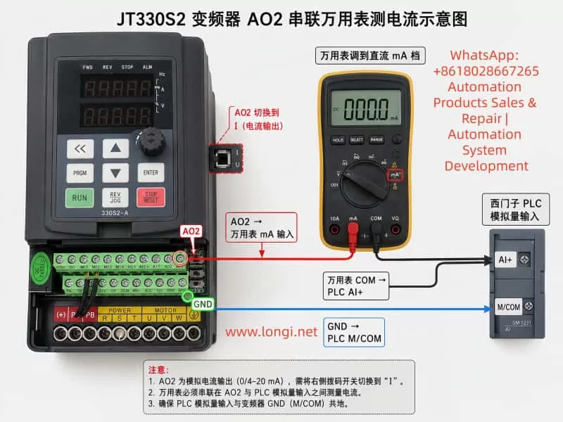
JT330S2 inverter AO2 analog current output measurement wiring diagram showing a digital multimeter connected in series between the inverter AO2 terminal and Siemens PLC analog input AI+, with GND connected to PLC M/COM, demonstrating correct 0–20mA current signal testing and AO2 current-output jumper setting.

1. Basic Function of AO2 Analog Output

The JT330S2 inverter provides two analog outputs:

AO1
AO2

These outputs can be configured to represent different operating parameters, including:

Running frequency
Set frequency
Output current
Output torque
Output power
Output voltage
Input analog values
Motor speed
Communication settings

In this application, the user wants the PLC to monitor the motor output current, therefore AO2 should be configured as:

F6-08 = 2

meaning:

AO2 output function = Output Current

This setting direction is correct. However, F6-08 only determines:

“What AO2 outputs”

It does NOT automatically guarantee:

“20A motor current = 20mA analog output”

Analog output accuracy also depends on:

Output mode
Zero offset
Gain
Full-scale mapping
PLC input scaling
Engineering unit conversion

Therefore, F6-08 is only the first step. The technician must still verify:

Whether AO2 is configured as current or voltage output
Whether AO2 outputs 0–20mA or 4–20mA
How the PLC analog module is configured
How the PLC program converts the raw analog value

2. Why the PLC Displays Only Half the Actual Current

The key field symptom is:

Actual motor current: 20A
PLC displayed current: 10A

An error that is exactly “half” is usually not random. It almost always indicates a scaling mismatch.

Suppose the inverter internally defines:

20mA = 40A

Then when the motor current is 20A, AO2 only needs to output half-scale current:

Approximately 10mA

Now suppose the PLC program assumes:

20mA = 20A

Then the PLC interprets 10mA as:

10A

This creates the observed condition:

Actual 20A
→ AO2 outputs approximately 10mA
→ PLC interprets 10mA as 10A

Therefore, the issue is most likely NOT that AO2 is malfunctioning. Instead, the scaling relationship between the inverter analog output and the PLC engineering conversion is inconsistent.


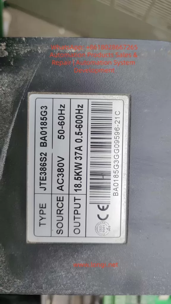
JTE386S2 BA0185G3

3. Measure the Actual AO2 Output Current First

One of the biggest mistakes in field troubleshooting is immediately changing parameters without measurement.

The correct approach is to first measure the real AO2 output current using a multimeter.

Unlike voltage measurement, current measurement must be performed in series.

The correct wiring method is:

Inverter AO2 → Multimeter mA Input
Multimeter COM → PLC Analog Input AI+
Inverter GND → PLC Analog M/COM

In practical terms:

Disconnect the wire between AO2 and PLC AI+
Insert the multimeter in series

The multimeter must be set to:

DC mA measurement mode

The red probe must be inserted into the:

mA terminal

and the black probe into:

COM

If the meter is accidentally placed in voltage mode, AC current mode, or connected in parallel, the reading will be incorrect and the meter fuse may even blow.


4. Using Measured Values to Determine the Root Cause

During testing, record three values simultaneously:

1. Inverter displayed output current
2. Multimeter measured AO2 current signal
3. PLC displayed current

Measurements should be taken at multiple load points:

Low load (e.g. 5A)
Medium load (e.g. 10A)
High load (e.g. 20A)

Case 1: Actual 20A → AO2 ≈ 10mA → PLC Displays 10A

This means the PLC display follows the analog signal correctly, but the engineering scaling range is too small.

The PLC likely assumes:

20mA = 20A

while the inverter output behaves like:

20mA = 40A

Typical PLC conversion formula:

Current = Raw_AI × 20 / 27648

should instead become:

Current = Raw_AI × 40 / 27648

This adjustment causes:

10mA → 20A

which restores correct display.


Case 2: Actual 20A → AO2 ≈ 20mA → PLC Displays 10A

In this case, the inverter analog output is already correct.

The fault is entirely on the PLC side.

Possible causes include:

Incorrect analog module range
Incorrect PLC scaling formula
Incorrect HMI engineering scaling
Additional divide-by-two logic in the program
Incorrect analog module configuration

If the PLC raw analog value already reaches near full scale but the displayed engineering value is still half, the inverter is NOT the problem.


Case 3: Actual 20A → AO2 Has Almost No Current Output

This suggests a hardware or wiring issue.

The technician should verify:

AO2 jumper/switch position
AO2 wiring
PLC analog input type
GND common reference
F6-08 parameter
F6-12 offset
F6-13 gain

On the JT330S2 control board, AO1 and AO2 can be configured as either:

Voltage output (V)
Current output (I)

If AO2 is still configured for voltage output while the PLC expects current input, readings will be abnormal.


5. Recommended Inverter Parameter Settings

For transmitting actual motor current through AO2:


AO2 Hardware Mode

Set AO2 jumper/switch to:

I = Current Output

Do NOT leave it at:

V = Voltage Output

AO2 Function Selection

F6-08 = 2

meaning:

AO2 outputs motor current

AO2 Offset

F6-12 = 0.0%

Normally keep default.

Improper offset adjustment can create false low-current readings.


AO2 Gain

F6-13 = 1.00

Normally keep default initially.

If measurements confirm the AO2 signal is exactly half the desired value, gain can be increased:

F6-13 = 2.00

However, increasing gain also risks premature saturation.

Example:

Originally:

40A = 20mA

After doubling gain:

20A = 20mA

Then any current above 20A can no longer be represented properly.

Therefore, adjusting PLC scaling is usually preferable.


6. PLC Engineering Unit Scaling Is Often Overlooked

Siemens S7-200 SMART analog modules typically convert analog current into digital values.

A common full-scale raw value is:

27648

for:

0–20mA

Engineering conversion formula:

Engineering_Value = Raw_AI × FullScale / 27648

The key question is:

What actual current does 20mA represent?

The PLC does not know automatically.

The programmer must define it.

If the PLC program assumes:

20mA = 20A

then:

10mA = 10A

If the inverter behavior is actually:

20mA = 40A

then the PLC formula must be updated accordingly.


7. 0–20mA and 4–20mA Must Not Be Confused

Industrial analog current signals are commonly:

0–20mA
4–20mA

0–20mA:

0mA = zero signal
20mA = full scale

4–20mA:

4mA = zero signal
20mA = full scale

4–20mA allows wire-break detection because signal loss drops below 4mA.

The following three elements must always match:

Inverter output type
PLC analog input type
PLC scaling formula

If one side uses 0–20mA and the other assumes 4–20mA, scaling errors will occur.


8. Why Special Output Modes Should Not Be Used Randomly

Some JT330S2 firmware versions include special AO2 scaling options such as:

100% = 1000A

These modes are usually intended for:

Special scaling
Communication mapping
Large-current systems
Manufacturer calibration

They are generally unsuitable for standard motor current monitoring applications.

For normal PLC monitoring:

F6-08 = 2

is the preferred choice.

Scaling corrections should then be handled through:

F6-13 gain adjustment
or
PLC engineering scaling

9. Recommended Field Commissioning Procedure

A practical troubleshooting workflow:


Step 1 — Verify Wiring

AO2 → PLC AI+
GND → PLC M/COM

For testing:

AO2 → Multimeter mA input
Multimeter COM → PLC AI+
GND → PLC M/COM

Step 2 — Verify AO2 Hardware Mode

AO2 jumper = I

Step 3 — Verify Parameters

F6-08 = 2
F6-12 = 0.0%
F6-13 = 1.00

Step 4 — Record Operating Data

Measure:

Actual motor current
AO2 mA signal
PLC raw analog value
PLC displayed engineering value

Step 5 — Analyze Results

Correct AO2 but wrong PLC display
→ PLC scaling issue

AO2 signal too small
→ Gain or scaling mismatch

No AO2 signal
→ Wiring/jumper/input mode issue

Unstable signal
→ Grounding/shielding/noise problem

10. Wiring and Safety Considerations

Even though AO2 is a low-level control signal, inverter commissioning still involves dangerous power circuits.

Important precautions:

Never modify power wiring while energized
Do not short 24V, 10V, or GND terminals
Current measurement must be series-connected
Use correct meter terminals
Avoid shorting AO2 to GND
Ensure proper common grounding
Use shielded analog cables
Separate analog cables from motor cables

Many analog signal issues are actually caused by:

Improper shielding
Noise interference
Incorrect grounding
Mixed routing with motor cables
Floating analog commons

rather than parameter settings.


11. Explaining the Problem to Customers

A practical explanation for customers is:

“Setting F6-08=2 only tells the inverter to output motor current through AO2. The PLC display depends on how many milliamps AO2 actually outputs and how the PLC converts those milliamps into amps. If actual current is 20A but PLC shows 10A, the scaling ratio is incorrect. First measure the real AO2 output current with a multimeter. If 20A corresponds to 10mA, either adjust PLC scaling so that 20mA equals 40A, or increase AO2 gain. If 20A already corresponds to 20mA, then the issue is entirely inside the PLC program.”

This explanation helps avoid unnecessary inverter replacement.


12. Conclusion

When using the JT330S2 inverter AO2 analog output to transmit motor current to a Siemens PLC, parameter:

F6-08 = 2

is correct, but it is only the function selection step.

The common field symptom:

Actual 20A
PLC displays 10A

is usually caused by mismatch between:

AO2 output scaling
PLC analog input scaling
Engineering conversion formulas

The proper diagnostic method is to:

Measure the real AO2 mA signal first

using a multimeter connected in series.

Then determine whether the issue lies in:

PLC scaling
AO2 gain
Wiring
Output mode
Grounding

In most practical applications, correcting PLC engineering scaling is preferable to increasing AO2 gain, because it avoids premature analog output saturation and preserves full measurement range.

The key principle in troubleshooting analog output systems is understanding the complete signal chain:

Motor Current
→ Inverter Internal Calculation
→ AO2 Analog Output
→ PLC Analog Acquisition
→ PLC Engineering Conversion
→ HMI Display

By testing and verifying each stage independently, technicians can rapidly locate the true cause of scaling errors and avoid unnecessary hardware replacement or repeated blind parameter adjustments.

Posted on

Troubleshooting Er24.1 and Er16.0 on the Zhishan K5 Servo Drive: Reverse Rotation Failure, Excessive Speed Deviation, and Overload Protection

In CNC equipment, automatic feeding systems, packaging machines, printing machines, dispensing machines, winding machines, and many other automation mechanisms, AC servo systems are responsible for accurate positioning, speed control, and torque output. Once a servo drive reports an alarm, the machine usually stops immediately. Compared with a standard inverter, a servo drive has stricter monitoring logic because it does not only check current, voltage, and temperature; it also continuously compares command position, command speed, actual encoder position, and actual feedback speed.

For this reason, when a servo system fails, the technician should not only ask whether the motor can rotate. It is more important to analyze the relationship between command, feedback, load, wiring, parameters, and the mechanical transmission structure.

In field applications, the Zhishan K5 series AC servo drive may show the following symptom: the drive powers on normally, the servo can be enabled, forward rotation may work, but reverse rotation fails. Once a reverse command is given, the motor may not move, may move slightly and stop, or may immediately trigger Er24.1. In some cases, Er16.0 also appears.

This fault may look like a defective servo drive, but the real cause may be mechanical jamming, excessive load, abnormal encoder feedback, incorrect motor phase wiring, wrong direction logic, active reverse limit signal, brake not released, or improper parameter settings. To solve this problem correctly, the alarm meaning must be combined with the real machine behavior.

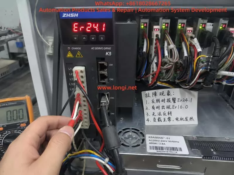
Zhishan K5 AC servo drive displaying Er24.1 speed deviation alarm inside an industrial control cabinet during on-site maintenance and troubleshooting.

1. The Meaning of Er24.1: Excessive Speed Deviation

For the K5 servo drive, Er24.1 generally means excessive speed deviation protection. Speed deviation is the difference between the speed commanded by the drive and the actual speed fed back by the motor encoder.

For example, the PLC or motion controller sends a reverse rotation command to the servo drive. The drive outputs three-phase current to make the motor rotate in reverse. However, the encoder feedback shows that the motor speed does not reach the expected value, or the motor almost does not move. In this case, the drive determines that the difference between command speed and actual speed is too large. To prevent overcurrent, overload, mechanical impact, or loss of control, the drive stops and reports Er24.1.

Therefore, Er24.1 does not necessarily mean that the drive is internally damaged. More accurately, it means:

The drive has issued a motion command, but the actual motor movement does not match the expected result.

Common causes include:

motor blocked by mechanical load;

reverse direction mechanically jammed;

mechanical hard limit reached;

motor brake not released;

load inertia too large;

acceleration or deceleration time too short;

motor U/V/W wiring wrong or loose;

encoder cable loose or abnormal;

motor and drive not matched;

reverse direction signal logic incorrect;

speed deviation detection threshold set too small;

servo gain not suitable for the machine.

If the actual symptom is “forward rotation works, but reverse rotation fails,” the key point is not only speed deviation. The real question is:

Why does the motor fail to follow the command only in reverse direction?

2. The Meaning of Er16.0: Overload Protection

Er16.0 is usually related to overload protection. Overload does not always mean an instant short circuit, and it does not always mean that the drive power module is damaged. In servo systems, overload usually means that the motor current has exceeded the allowed range for a certain period of time. The drive judges that the motor or drive is carrying excessive load.

If the machine is mechanically jammed in reverse direction, the drive will increase output current in an attempt to make the motor rotate. But because of mechanical resistance, brake locking, wiring error, or abnormal feedback, the motor cannot reach the target speed. This may first trigger Er24.1. If the high current continues, Er16.0 may also appear.

In other words, Er24.1 and Er16.0 are often connected:

A reverse command is given.

The motor cannot rotate correctly because of mechanical load, limit signal, brake, wiring, or feedback problem.

The drive increases output current.

The encoder feedback speed cannot follow the command.

The drive reports Er24.1.

If high current continues, the drive reports Er16.0.

Therefore, when Er24.1 appears together with Er16.0, do not treat them as two unrelated faults. The correct diagnostic logic is:

Find out why the motor cannot follow the command first, then determine whether overload is the cause or the result.

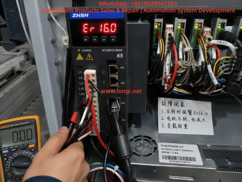
Zhishan K5 AC servo drive showing Er16.0 overload alarm while a technician performs electrical diagnostics inside an industrial automation control panel.

3. When Reverse Rotation Fails, Mechanical Problems Are Highly Suspect

In real repair work, if a servo system can rotate forward but cannot rotate backward, the mechanical side must be checked first. Many technicians immediately suspect the servo drive and replace it. However, after replacing the drive, the same alarm may still appear because the root cause is not in the drive.

Common mechanical causes include the following.

The first is one-direction mechanical jamming. Lead screws, guide rails, belts, chains, gearboxes, feeding wheels, and clamping mechanisms may move smoothly in one direction but become tight in the opposite direction. Lack of lubrication, damaged bearings, worn lead screw nuts, misaligned belts, damaged gearbox teeth, or foreign objects may all cause reverse movement failure.

The second is a mechanical hard limit. If the mechanism has reached the end position, and the limit switch or software limit does not stop the axis correctly, the servo may command movement against a dead stop. The motor receives torque command but cannot move. Current rises quickly, actual speed remains very low, and the drive reports an alarm.

The third is brake failure. If the servo motor has an electromagnetic brake, the brake must be released before motion. If the brake power supply is missing, the brake relay contact is damaged, the brake coil is faulty, or the brake mechanism is stuck, the motor may hum, vibrate, or fail to rotate. Sometimes the brake is not completely locked but only partially released. This is more difficult to detect because the motor may rotate at no load but fail under load.

The fourth is asymmetric load. Many machines do not have the same load in forward and reverse directions. Lifting mechanisms, feeding systems, pressing rollers, and clamping systems may have very different resistance depending on direction. If reverse direction happens to be the heavy-load direction, Er24.1 and Er16.0 may appear more easily.

For this reason, when a K5 servo drive reports Er24.1 or Er16.0 and the machine cannot reverse, do not start by changing parameters. First confirm whether the machine is mechanically able to move in reverse.

4. The Most Effective First Test: Disconnect the Load

The fastest way to separate mechanical problems from electrical problems is to disconnect the motor from the mechanical load. This means loosening the coupling, belt, gear connection, or other transmission connection so that the motor can run freely without load.

Do not test at high speed first. Use a low-speed jog command, such as 30 rpm, 50 rpm, or 100 rpm, and observe whether the motor rotates smoothly.

Check the following:

Can the motor rotate forward without load?

Can the motor rotate backward without load?

Does the motor vibrate during reverse rotation?

Does it make abnormal noise?

Does Er24.1 still appear?

Does Er16.0 still appear?

If the motor runs normally in both directions without load, the servo drive, motor, and encoder are probably not the main problem. The focus should move to mechanical load, brake, limit switch, or machine process.

If reverse rotation still triggers Er24.1 without load, the problem is more likely in motor wiring, encoder feedback, control signal, parameters, motor, or drive hardware.

This simple test is extremely valuable because it can quickly divide the fault into mechanical side or electrical side. Many servo faults take too long to repair because the technician keeps adjusting drive parameters without first separating the motor from the machine.

5. Check U/V/W Motor Wiring and Encoder Feedback

A servo motor is not the same as a normal three-phase induction motor. For a normal induction motor, changing two phases can reverse the direction. But for a servo motor, U/V/W phases cannot be changed randomly. The drive output phase sequence must correspond correctly to the encoder feedback angle. If the motor phase wiring is wrong, or if the encoder feedback direction does not match the drive output, the servo loop may become unstable.

Possible symptoms include vibration, no torque, excessive current, overcurrent, speed deviation alarm, or overload alarm.

The following points must be checked carefully:

U, V, and W are connected to the correct drive terminals;

motor cable has no broken wire;

terminal screws are tight;

connector pins are not bent or pushed back;

motor cable is not damaged;

encoder connector is fully inserted;

encoder cable shield is properly grounded;

encoder cable is not bundled together with power cables for a long distance;

motor and drive belong to the same axis;

motor cable and encoder cable are not crossed with another axis.

Multi-axis machines are especially prone to cable mix-up. For example, the motor power cable may belong to axis A, but the encoder feedback cable may be connected to axis B. Once the motor and encoder are not matched, the drive cannot close the loop correctly. The result may be immediate alarm, vibration, or dangerous motion.

If the fault appeared after repair, transportation, rewiring, motor replacement, or drive replacement, wiring error must be treated as a high-probability cause.

6. Check Reverse Limit and Inhibit Signals

“Cannot reverse” may also be caused by external control signals. A servo drive usually receives signals from a PLC, motion controller, or control board, including pulse command, direction signal, servo enable, positive limit, negative limit, emergency stop, alarm reset, and inhibit signals.

If the reverse direction limit signal is active, the drive may block movement in that direction. The field symptom may look like the motor cannot reverse, or it may stop immediately when reverse command is given.

Check these signals:

positive limit input;

negative limit input;

forward inhibit input;

reverse inhibit input;

emergency stop input;

servo enable input;

pulse input;

direction input;

PLC output logic;

control common wiring;

input terminal function assignment.

Some machines use normally closed limit logic, while others use normally open logic. If a limit switch, PLC output card, wiring, or parameter has been changed, the input logic may become inverted. The machine may not actually be at the negative limit, but the drive may think the negative limit is active, so reverse movement is blocked.

The correct method is not only to watch whether the limit switch moves mechanically. The technician must confirm the actual input status seen by the servo drive. This can be done through the drive monitor function or by measuring the terminal voltage with a multimeter.

7. Check Whether the Brake Is Released

If the servo motor has a holding brake, the brake circuit must be checked separately. Many technicians assume that the brake will automatically release when the servo is enabled, but in actual machines this is not always true.

The brake often requires an independent 24 VDC supply. It may be controlled by a relay, PLC output, or drive output. If the brake power supply is missing, the relay contact is burnt, the brake coil is damaged, or the brake mechanism is stuck, the motor will be forced to rotate against the brake.

Check the following:

brake rated voltage;

whether brake voltage appears after servo enable;

whether the brake makes a clear release sound;

whether the motor shaft can rotate freely after brake release;

whether brake power supply capacity is enough;

whether relay contacts are burnt;

whether brake coil is open or shorted;

whether brake gap is abnormal;

whether the brake is mechanically stuck.

If the brake is not released and the servo is forced to run, Er24.1 and Er16.0 can appear together. The drive outputs current, but the motor does not reach commanded speed. The result is speed deviation and overload.

8. Parameter Adjustment Should Not Be the First Solution

When technicians see speed deviation alarm, they may want to increase the speed deviation threshold. When they see overload alarm, they may want to increase acceleration time, reduce gain, or modify torque limit. Parameter adjustment can sometimes reduce false alarms, but it should not be used to hide a real mechanical or wiring problem.

If the mechanism is jammed, increasing the speed deviation threshold only delays the alarm. The motor may remain stalled for a longer time, causing motor overheating, drive damage, or mechanical deformation.

If U/V/W wiring or encoder feedback is wrong, parameter adjustment cannot solve the root problem. It may only make the fault more dangerous.

Parameter checking should be done after mechanical and wiring checks. Important parameter groups include:

speed deviation detection threshold;

speed deviation detection time;

acceleration time;

deceleration time;

speed loop gain;

position loop gain;

torque limit;

electronic gear ratio;

pulse input mode;

direction signal polarity;

motor capacity setting;

encoder-related settings;

positive and negative limit input assignment.

Do not restore factory parameters blindly. Machine builders may have set electronic gear ratio, limit logic, pulse mode, gain, and control mode according to the actual machine. A careless factory reset may make the machine unable to return to its original working condition.

9. How to Distinguish Drive Fault, Motor Fault, and External Fault

A practical diagnostic sequence should follow this order:

external mechanical system;

motor and encoder wiring;

control signals;

parameters;

drive and motor hardware.

If the motor runs normally without load but alarms under load, suspect mechanical load, brake, guide rail, lead screw, belt, gearbox, or machine jamming.

If forward works but reverse fails, suspect reverse mechanical resistance, negative limit, reverse inhibit, direction logic, or reverse acceleration impact.

If both forward and reverse vibrate or lack torque, suspect U/V/W wiring, encoder cable, motor matching, or servo gain.

If the alarm appears immediately after servo enable, suspect encoder fault, motor cable fault, drive power module, motor winding, brake locking, or serious parameter mismatch.

If the alarm appears randomly, suspect loose connectors, poor shield grounding, encoder interference, terminal contact problem, unstable power supply, or intermittent mechanical jamming.

If replacing the drive does not change the fault, the problem is probably not inside the drive. It is more likely in motor, encoder, wiring, mechanics, or control signal.

If replacing the motor solves the problem, the original motor may have encoder, winding, or brake failure.

If replacing the encoder cable solves the problem, the original cable or connector has a hidden fault.

If the same drive and motor work normally on a test bench but fail after installation, the machine mechanism or control logic must be checked.

10. Recommended Field Troubleshooting Procedure

For a Zhishan K5 servo drive showing Er24.1, sometimes with Er16.0, and failing to reverse, the following procedure is recommended.

First, record the alarm timing. Confirm whether the alarm appears at power-on, at servo enable, during forward rotation, or only during reverse rotation. The timing is more important than the alarm code alone.

Second, check whether the mechanism can move backward. With power off, manually rotate the transmission mechanism if possible. Check for tight points, hard stops, abnormal noise, brake locking, or one-direction resistance.

Third, disconnect the load and test the motor alone. Run forward and reverse at low speed. If the motor runs normally without load, focus on the mechanical side. If reverse still alarms without load, focus on wiring, feedback, control signal, or parameter.

Fourth, check the brake. If the motor has a brake, confirm that it is really released, not only that the control signal exists.

Fifth, check U/V/W and encoder wiring. Confirm motor phase wiring, encoder cable, shielding, connectors, and axis matching.

Sixth, check control input status. Focus on negative limit, reverse inhibit, emergency stop, servo enable, direction signal, and pulse command.

Seventh, check parameters. Confirm speed deviation threshold, acceleration and deceleration time, torque limit, direction polarity, pulse mode, electronic gear ratio, and limit input function assignment.

Eighth, test again at low speed. Start with no load, then light load, then normal load. Observe current, speed feedback, machine movement, and alarm behavior at each step.

Ninth, use substitution testing only when necessary. A same-model motor, encoder cable, or drive can be exchanged for comparison, but wiring and parameters must be confirmed before testing to avoid causing new damage.

11. Common Mistakes During Repair

Several mistakes are common when repairing this type of servo fault.

The first mistake is increasing the speed deviation threshold immediately after seeing Er24.1. This may hide mechanical jamming and cause more serious damage.

The second mistake is assuming the drive power module is bad after seeing Er16.0. Overload is often caused by load or motion conditions, not necessarily by drive hardware failure.

The third mistake is repeatedly testing the machine without disconnecting the load. If the mechanism is jammed, repeated testing sends high current into the motor and drive.

The fourth mistake is swapping U/V/W phases casually. A servo motor cannot be treated like a normal induction motor.

The fifth mistake is checking only the motor power cable and ignoring the encoder cable. Servo control is closed-loop. Encoder feedback problems can also cause speed deviation and overload.

The sixth mistake is looking only at the physical limit switch but not the drive input status. A switch may move correctly, but the drive terminal may receive the wrong signal.

The seventh mistake is restoring factory settings blindly. This may erase the original electronic gear ratio, limit logic, pulse mode, and gain settings.

The eighth mistake is ignoring the brake. A brake that does not fully release is a frequent cause of overload and speed deviation alarms.

12. Conclusion

When a Zhishan K5 series servo drive reports Er24.1, the core meaning is excessive speed deviation. When Er16.0 appears as well, the system also has an overload condition. For the symptom “reverse rotation failure,” the correct conclusion is not to immediately condemn the servo drive. The most likely causes are reverse-direction mechanical resistance, active reverse limit, brake not released, excessive load, abnormal encoder feedback, wrong wiring, or incorrect direction logic.

The correct repair method is to separate the mechanical side from the electrical side first. Disconnect the load and test forward and reverse rotation at low speed. If the motor works normally without load, check the mechanism, brake, and limit signals. If the alarm still appears without load, check U/V/W wiring, encoder cable, control terminals, direction command, and parameters.

Parameter adjustment should be used only after the real cause is identified. It should never be used to cover up mechanical jamming or wiring errors.

A servo alarm is the result of closed-loop monitoring. Er24.1 means the actual motor speed does not follow the command. Er16.0 means the motor or drive is overloaded. Only by analyzing command, feedback, current, mechanical load, and control signals together can the technician locate the fault quickly, avoid unnecessary part replacement, reduce downtime, and prevent further damage to the motor, drive, and machine mechanism.

Posted on

Troubleshooting the TECO JSDAP Servo Drive RL-04 Overcurrent Alarm: Fault Mechanism and On-Site Diagnostic Method

In CNC machine tools, turret mechanisms, feeder axes, clamping axes, and automated special-purpose machines, servo systems are responsible for precise positioning, fast response, and closed-loop control. Compared with a standard inverter driving an induction motor, a servo system has much higher requirements for motor power wiring, encoder feedback wiring, parameter matching, mechanical load condition, and control sequence. Once any of these links becomes abnormal, the servo drive may not merely show unstable speed or positioning deviation. Instead, it may directly trigger protective alarms such as overcurrent, encoder fault, overload, or excessive position deviation.

In the TECO JSDAP series servo drive, one common field alarm is RL-04, AL-04, or simply 04 on the keypad display. In actual repair work, many users tend to interpret this alarm as “high motor current” or “heavy load.” However, from a maintenance perspective, alarm 04 should not be treated as a simple overload. It is closer to an instantaneous abnormal current protection in the main power circuit. Possible causes include incorrect U/V/W motor phase wiring, abnormal encoder feedback, servo motor winding defects, damaged drive power module, mismatch between parameter Cn030 and the actual motor, mechanical jamming, or a brake that has not been released.

When a machine-tool customer reports that “the servo motor should normally rotate two turns, but now it only moves briefly and then reports RL-04 overcurrent,” this symptom has strong diagnostic value. It usually means the system is not completely faulty at power-on. Instead, the alarm occurs when the servo is enabled, the drive begins outputting current, and the motor just starts to respond. The diagnostic focus should therefore be placed on why the current rises abnormally at the moment of operation, rather than only looking at the auxiliary alarm displayed on the CNC screen.

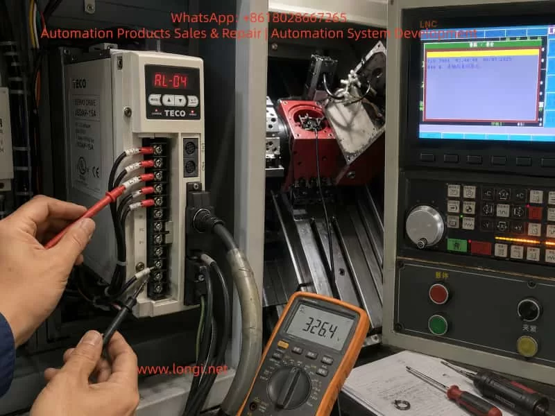
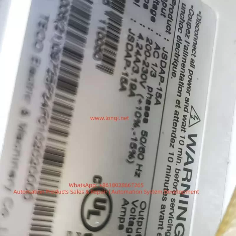
TECO JSDAP-15A servo drive showing an RL-04 overcurrent alarm during CNC machine troubleshooting, with visible drive label, wiring terminals, technician test probes, and LNC control panel in the background.

1. Basic Meaning of the TECO JSDAP RL-04 Alarm

On the TECO JSDAP series servo drive, alarm 04 generally corresponds to drive overcurrent. From the drive’s protection logic, overcurrent does not simply mean that the load is slightly higher than usual. It means that the main circuit has detected current exceeding the protection threshold. To protect the IGBT/IPM power module, motor windings, and mechanical system, the drive immediately cuts off output and issues an alarm.

For alarm 04, the diagnostic direction normally includes checking whether the motor-side U, V, W wiring and encoder wiring are normal, and confirming that the wiring follows the standard connection diagram. If the alarm still exists after the power has been turned off for a period and then reapplied, the fault may involve the internal power transistor module of the servo drive or severe electrical noise interference.

This means RL-04/04 is not caused by one single fixed fault. It is a protective result for a class of abnormal output-current conditions. Maintenance personnel must judge the cause together with the timing of the alarm: whether it appears immediately after power-on, after servo enable, after the motor moves briefly, after a period of running, under mechanical load, or even when the motor is disconnected. Different timing points correspond to completely different fault ranges.

2. Why “The Motor Moves Once and Then Reports 04” Is Important

In field service, customers often describe the problem as “the servo motor moves a little and then alarms,” “normally it should rotate two turns, but now it stops immediately,” or “after reset, the same thing happens again.” This simple description actually contains several important clues.

First, the drive is not completely unable to power up. If the drive reports 04 immediately after control power or main power is applied, the first suspects would be the drive power module, current detection circuit, main-circuit short circuit, or serious internal component failure. In this case, however, the alarm occurs after operation begins, which means the drive can at least complete part of its initialization. The fault is triggered during output.

Second, the motor has made a short movement. If the motor can move briefly, it means the main circuit has probably output three-phase current, and the servo enable signal and part of the control logic are present. But when the motor starts and the alarm immediately appears, it suggests that the drive detects an abnormal closed-loop control condition. The current response may be much higher than expected, or the motor feedback may not match the drive output, causing the servo amplifier to increase current sharply before tripping.

Third, if the motor should normally complete two revolutions but now cannot, the axis may be involved in homing, turret indexing, clamping-axis positioning, or a fixed travel sequence. If the CNC screen also displays a message such as “clamping axis not returned to home,” that CNC message may not be the root cause. It may simply be the interlock result after the servo axis fails to complete its action. The true primary fault should still be judged from the servo drive display.

Therefore, “one brief movement followed by RL-04” should not be directly judged as motor failure, nor should it immediately be judged as drive failure. The correct approach is to distinguish mechanical load problems, motor feedback problems, power wiring problems, parameter mismatch, and drive hardware failure.

3. Common Cause 1: Incorrect, Loose, or Poorly Insulated U/V/W Motor Wiring

The U, V, W three-phase power wires of a servo motor cannot be swapped casually like those of a standard induction motor. For an ordinary three-phase induction motor, swapping any two phases mainly changes the rotation direction. But an AC servo system is closed-loop controlled. The current vector output by the drive must strictly correspond to the rotor position feedback from the encoder. If the U/V/W phase sequence is wrong, or if one phase is loose or intermittently connected, the drive may find that the motor feedback direction, speed, or phase does not match the expected response. It may then rapidly increase current to correct the error, eventually causing overcurrent protection.

In real field cases, U/V/W problems commonly occur in the following situations:

The motor or drive has been removed for repair, and the wiring was restored without a reference photo.

The terminal screws are aged or not tightened, and vibration causes poor contact during operation.

The motor cable has been worn by the drag chain, sheet-metal edge, or oil-contaminated area, damaging the insulation.

The motor connector has oil or water ingress, causing leakage or short circuits between pins.

The motor cable was replaced, but the wire colors do not match the original factory definition.

The drive output cables are bundled together with other strong-current cables, causing interference or insulation damage.

For field maintenance, wire color alone should not be used as the final judgment. The motor nameplate, connector pinout, original wiring diagram, and actual terminal marks must all be compared. After power-off and full discharge, check whether U, V, and W correspond correctly from the drive to the motor. Then measure the resistance of U-V, V-W, and W-U with a multimeter. The three values should be basically balanced. Next, measure insulation from U/V/W to the motor frame or ground. A standard multimeter can only detect serious short circuits. If insulation degradation is suspected, a megohmmeter should be used. In servo motors, insulation problems may not appear as a complete static short circuit, but may become obvious only when the drive outputs PWM voltage.

JSDAP-15A

4. Common Cause 2: Abnormal Encoder Feedback

The core of a servo system is closed-loop control. The drive not only outputs three-phase current to the motor, but also reads encoder feedback in real time to determine rotor position, speed, and direction. If encoder feedback is lost, reversed, distorted, intermittent, or affected by broken wires or poor connector contact, the drive’s judgment of motor status becomes unreliable.

Encoder faults do not always immediately appear as a dedicated encoder alarm. In some cases, the encoder signal seems normal while stationary, but once the motor starts, vibration causes an internally broken conductor to lose contact, or the feedback position jumps. The drive may then output abnormal current and finally show overcurrent protection. In machine-tool environments, oil mist, coolant, metal chips, long-term vibration, and repeated drag-chain bending can all cause hidden encoder cable damage.

Encoder troubleshooting should be performed systematically. First, power off and unplug the encoder connector. Check whether the pins are bent, retracted, oxidized, or contaminated by oil. Second, inspect the cable sheath for crushing, pulling, or excessive bending. Third, check whether the encoder power supply is normal. Many systems use 5 V encoder power, but the actual value should be confirmed according to the motor and manual. Fourth, if a same-model motor or cable is available, cross-substitution is the most effective method. Encoder cables are one of the most easily overlooked but most common fault points in field service.

If the motor is separated from the mechanical load and still shakes, rushes briefly, or reports 04 as soon as it is enabled, while U/V/W wiring shows no obvious short circuit, encoder feedback should be placed very high on the suspect list.

5. Common Cause 3: Mechanical Jamming, Brake Not Released, or Clamping Mechanism Not Open

In machine tools, a servo motor often does not drive a light free-running load. It may be connected through a coupling, timing belt, reducer, ballscrew, turret, clamping mechanism, homing mechanism, or other mechanical transmission. If the mechanical side is not fully released, the servo motor may face a near-stall load at startup. The current rises instantly, and the drive may report RL-04.

The word “no-load rotation” must be clarified. Customers may use it in two different ways. One means the motor is physically disconnected from the machine and the motor shaft is truly unloaded. The other simply means the machine is running an “empty cycle” or homing program, while the motor is still connected to the mechanical structure. These two meanings are completely different for diagnosis.

If the motor remains connected to the mechanism, the following problems may cause overcurrent:

The mechanical brake has not released.

The turret clamping mechanism has not opened.

Hydraulic or pneumatic pressure is insufficient, so unclamping is incomplete.

The reducer is internally damaged or jammed.

The ballscrew, bearing, or guideway resistance is too high.

The coupling is eccentric, over-tightened, or deformed during installation.

The home switch or limit switch state is incorrect, causing the axis to drive into a mechanical stop.

The machine has been idle for a long time, and oil sludge, chips, or dried coolant has blocked the mechanism.

For servo motors with mechanical brakes, the brake power supply must be checked carefully. A brake usually requires an external DC 24 V control supply to release. The brake wires must not be mistaken for ordinary signal wires. If the brake is not released, the motor is effectively starting against a locked rotor, and overcurrent is almost unavoidable.

The most effective way to identify a mechanical problem is to disconnect the coupling, timing belt, or reducer and let the motor truly run without load. If the motor runs normally after being disconnected and no longer reports 04, the drive and motor are probably not the main cause. The fault should be traced to the mechanical side. If the motor is completely disconnected and still reports 04 immediately after movement, the mechanical side can largely be excluded, and the electrical system should be checked first.

6. Common Cause 4: Incorrect Cn030 Motor Matching Parameter

The TECO JSDAP series drive cannot run any motor arbitrarily. The drive must know the connected motor’s power, rated current, rated speed, encoder type, inertia class, and related characteristics. The parameter Cn030 is used for the motor/drive series matching setting. The diagnostic item dn-08 can be used to check the currently configured drive and motor combination. If the displayed combination does not match the actual motor, Cn030 must be corrected.

This point is especially important for second-hand machine tools, old equipment repair, drive replacement, and parameter initialization. Many field failures are not caused by damaged hardware, but by a mismatch between the drive parameters and the actual motor. For example, the drive may be a JSDAP-15A, but the connected motor may have a different encoder type, rated current, or power class. If Cn030 is set for another motor combination, the drive’s understanding of motor electrical angle, rated current, and feedback resolution will be wrong. The result may be vibration, abnormal movement, or overcurrent immediately after operation.

Parameter mismatch is common in the following situations:

The drive has been replaced, but the original parameters were not imported.

The drive was repaired and reset to default parameters.

A used drive was installed as a substitute, with similar appearance but wrong parameter settings.

The motor was replaced, but the old drive parameters were retained.

Only part of the motion parameters was restored, while the motor-series parameter was ignored.

Different JSDAP capacity ranges or encoder specifications were mixed incorrectly.

Therefore, when troubleshooting RL-04, hardware measurement alone is not enough. The drive’s diagnostic item dn-08 should be checked and compared with the actual motor nameplate. If the motor model, power, speed, or encoder specification does not match the drive setting, Cn030 must be corrected before trial operation. Repeated testing under wrong parameter conditions not only fails to solve the problem, but may also expand the damage.

7. Common Cause 5: Servo Motor Failure

Servo motor failure can also trigger RL-04. Common motor faults include winding turn-to-turn short circuit, three-phase imbalance, insulation breakdown to ground, encoder internal failure, bearing seizure, rotor demagnetization, or brake mechanism failure.

Turn-to-turn short circuit is a relatively hidden fault. It may not show as a complete U/V/W short circuit. When measured with a standard multimeter, one phase resistance may only be slightly different, or the difference may not be obvious. However, once the drive outputs PWM current, the shorted turns generate abnormal current and heat, causing the drive to trip on overcurrent. Motors that have overheated, been contaminated by oil or water, or suffered insulation aging are more likely to develop this fault.

Insulation degradation to ground is also common. In machine-tool environments, coolant, oil mist, and metal powder can enter the motor connector or junction area, causing leakage to ground. Servo drives are sensitive to output-side leakage and current abnormalities. When leakage current becomes large, the drive may report 04 or another main-circuit alarm.

Motor bearing seizure should not be ignored either. If the motor shaft feels tight, has periodic sticking points, produces abnormal noise, or feels as though it is scraping internally, the bearing, brake, or internal mechanical structure may be damaged. A motor with a brake cannot be rotated normally unless the brake is released, so the brake-release condition must be confirmed before judgment.

For the motor itself, the most effective method is still cross-substitution. If a same-model normal motor is available, install the original motor on a known-good axis, or connect a known-good motor to the faulty drive. If the fault follows the motor, the motor or encoder is confirmed as the likely cause. If the fault remains with the original drive or original machine axis, continue checking the drive, cable, and mechanical load.

8. Common Cause 6: Drive Power Module or Current Detection Circuit Failure

If the motor, cable, encoder, parameters, and mechanical load have all been excluded, the drive itself must be considered. The power module inside the JSDAP servo drive converts the DC bus voltage into three-phase output current for the servo motor. If the IGBT/IPM module is aged, partially shorted, or if the gate drive circuit or current detection circuit is abnormal, alarm 04 may appear during operation.

Drive hardware failure often appears in the following ways:

The drive reports 04 even when the motor is disconnected.

Any connected motor causes the same 04 alarm.

The drive runs briefly when cold but frequently reports 04 after warming up.

The output three-phase current is obviously unbalanced.

The motor produces abnormal squealing or vibration before alarm.

There is a burnt smell, visible explosion mark, heavy oil contamination, or dust accumulation inside the drive.

The power module shows abnormal readings in diode-mode testing.

After power-off and full discharge, an experienced technician may perform a preliminary diode-mode check between U/V/W and the DC bus points. However, this type of inspection must be done by qualified personnel. A servo drive contains high-voltage capacitors, and dangerous voltage may remain after power is turned off. Touching internal circuits before the charge indicator is off is unsafe.

If the drive power module is confirmed to be damaged, parameter reset or external cable replacement will not solve the problem. The drive must be inspected internally, including the IPM/IGBT, gate drive optocouplers, current sensors, DC bus capacitors, snubber circuit, power supply board, and control board. For old machine tools, the external motor and cables should also be checked for the original cause. Otherwise, the repaired drive may fail again after installation.

9. Correct On-Site Troubleshooting Sequence

For alarms like RL-04, the diagnostic sequence is very important. If the drive is removed and repaired immediately, time may be wasted. If the mechanical system is jammed and the operator repeatedly resets and retries the machine, the drive power module may be damaged. A reasonable diagnostic procedure is as follows.

First, confirm the true alarm source. CNC screen messages such as “clamping axis not returned to home,” “servo abnormal,” or “axis not ready” are often system interlock messages, not necessarily the root cause. A clear photo of the servo drive display must be taken to confirm whether the alarm is 04, AL-04, or RL-04.

Second, observe the alarm timing. If the alarm appears immediately after power-on, suspect the drive body, main-circuit short circuit, or serious wiring error first. If it appears after servo enable, focus on motor wiring, encoder wiring, and parameters. If it appears only at a fixed mechanical position, mechanical jamming, limit status, clamping mechanism, and program sequence become more suspicious.

Third, disconnect the mechanical load. Separate the motor from the coupling, timing belt, or reducer so the motor can truly run unloaded. If it runs normally unloaded, the mechanical side is the priority. If it still alarms unloaded, the electrical side is the priority.

Fourth, check U/V/W and encoder wiring. Confirm phase order, terminal tightness, connector condition, shielding, grounding, insulation, and possible internal cable breakage. Pay special attention to drag-chain cables and oil-contaminated connectors.

Fifth, check Cn030 and dn-08. Confirm whether the drive model, motor model, power, speed, and encoder specification match. This step is essential for second-hand machines and machines whose drives have been replaced or repaired.

Sixth, test the motor. Check three-phase resistance balance, insulation to ground, brake release, shaft rotation resistance, and encoder feedback condition.

Seventh, perform cross-substitution. Use a known-good same-model motor, cable, or drive for comparison. Cross-substitution is more reliable than guessing.

Eighth, evaluate drive hardware. If the drive reports 04 without the motor connected, or if the same alarm remains after replacing the motor and cable, the drive should enter the internal repair process.

10. Analysis of the CNC “Clamping Axis Not Returned to Home” Message

On some CNC lathes or special-purpose machines, the servo axis may not be a standard X/Z feed axis. It may be used for a clamping axis, turret, indexing table, feeder mechanism, or auxiliary homing mechanism. When the CNC screen displays “clamping axis not returned to home,” this does not necessarily mean the home switch is faulty. It may mean the servo axis reported RL-04 immediately after starting during the homing process, so the PLC never received the home-complete signal.

In this situation, the fault chain should be divided into two layers.

The lower-level fault is the servo drive 04 overcurrent alarm.
The upper-level fault is the CNC/PLC message caused by the servo axis failing to complete the required motion.

If only the upper-level alarm is handled, such as replacing the home switch, changing the PLC input, or forcing home completion, the real problem may remain. The correct method is to make the servo axis run stably first, then handle the homing logic. For clamping, unclamping, turret positioning, and similar mechanisms, pneumatic or hydraulic signals are often required before servo movement. If the unclamp signal is not complete and the servo axis is forced to move, the motor is effectively starting against a mechanical lock, so overcurrent is a reasonable result.

For JSDAP servo alarms on clamping-axis or turret mechanisms, the following items should be checked at the same time:

Whether the unclamping solenoid valve operates.

Whether air pressure or hydraulic pressure meets the required level.

Whether the clamped and unclamped position switches provide correct feedback.

Whether the mechanical lock pin has fully retracted.

Whether the homing direction is correct.

Whether the servo enable sequence occurs after unclamping is completed.

Whether an abnormal PLC input causes the servo to start under the wrong condition.

11. Maintenance Precautions

When dealing with RL-04, frequent reset and forced operation are not recommended. Every overcurrent trip stresses the power module, motor winding, and DC bus capacitors. If the actual fault is U/V/W short circuit, unreleased brake, or mechanical jamming, repeated trial operation can turn a repairable minor fault into a damaged power module.

U/V/W should also not be swapped casually to “test direction.” In a servo system, direction should be corrected through parameters, command settings, or proper motor matching, not by randomly swapping output phases like an induction motor. Incorrect phase sequence may cause closed-loop runaway and instantaneous current shock.

Encoder wiring must not be modified randomly either. Encoder feedback is a low-voltage high-speed signal. It should use proper shielded cable and be routed away from power wiring. Shield grounding should follow the original design. Multiple random grounding points can create interference loops. If the encoder cable has been soaked in oil or repeatedly bent in the drag chain, replacing the cable is often more effective than merely cleaning the connector.

For old machine tools, the cabinet environment also matters. Oil mist, metal dust, poor heat dissipation, fan failure, poor grounding, supply voltage fluctuation, and strong electrical interference can all reduce servo system stability. The drive should be installed in an environment with proper ventilation, limited dust and oil mist, reliable grounding, and sufficient heat dissipation.

12. Conclusion

The TECO JSDAP servo drive RL-04 or 04 alarm is essentially a drive overcurrent protection. It may be caused by a damaged drive power module, but in machine-tool field service, more common causes include abnormal U/V/W motor power wiring, encoder feedback problems, mechanical jamming, unreleased brake, clamping mechanism not open, or mismatch between parameter Cn030 and the actual motor.

For the symptom “the servo motor only moves briefly and then reports RL-04, while it should normally rotate two turns,” the most important diagnostic method is to disconnect the motor from the mechanical load and perform a true no-load test. If the motor runs normally after being disconnected, focus on the mechanical lock, brake, reducer, turret, or clamping-axis mechanism. If it still reports 04 when disconnected, focus on U/V/W wiring, encoder cable, motor body, Cn030/dn-08 matching, and drive hardware.

When repairing this type of fault, do not rely only on the CNC screen message, and do not immediately assume the drive is damaged. The correct procedure is: confirm the alarm source, observe the alarm timing, disconnect the mechanical load, check power wiring, check encoder feedback, verify parameters, test the motor, perform cross-substitution, and then repair the drive if necessary. This sequence reduces misjudgment, lowers unnecessary replacement cost, and prevents repeated trial operation from expanding the fault.

In actual machine-tool maintenance, RL-04 is not an isolated alarm. It is the protective result of interaction among the servo drive, motor, cable, mechanical structure, and PLC sequence. Only by analyzing it as a complete system can the real cause be found.

Posted on

Hailipu HIP320 VFD EFO Fault: Causes, Diagnosis, and Repair Guide

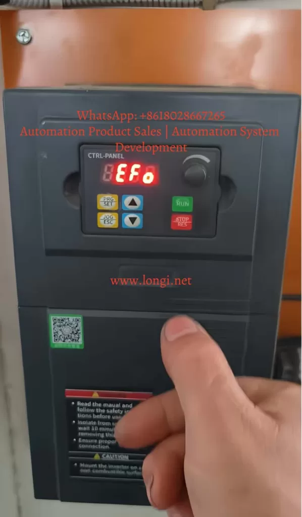
On Hailipu HIP320 series variable frequency drives, the EFO alarm is not a normal parameter warning. It is a power module fault. According to the HIP320 manual, EFO fault code 10 may be caused by output short circuit or grounding, instantaneous overcurrent, control board abnormality or severe interference, and damaged power components.

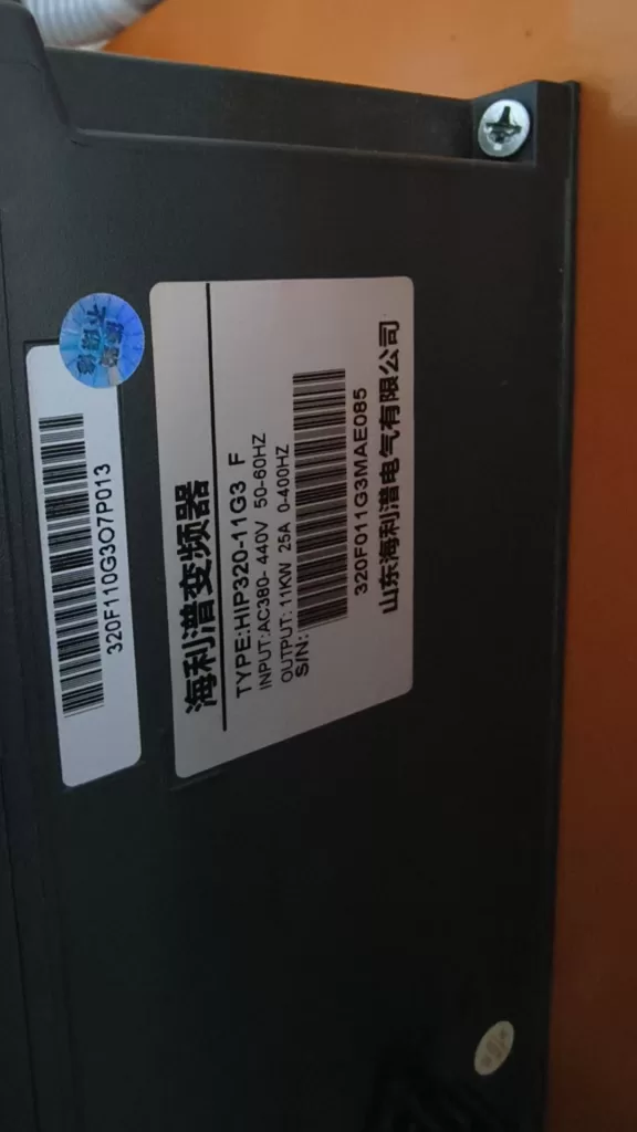
The unit shown in the photo is HIP320-11C3_F, with AC 380–440V input, 11kW output power, 25A rated output current, and 0–400Hz output frequency. When this type of drive reports EFO during operation, the fault should be diagnosed around the output circuit, motor cable, motor insulation, load condition, IGBT module, current detection circuit, driver board, and control board.

1. What EFO Means on the HIP320 Series

EFO means that the inverter has detected a serious abnormal condition in the power output section. It is more severe than a simple overload alarm.

A normal overload fault usually develops over time. For example, the motor is overloaded for a long period, the motor rated current is set incorrectly, or the load is too heavy. However, EFO often appears suddenly, especially during starting, acceleration, or when the inverter output is under stress.

Typical EFO symptoms include:

The inverter powers on normally, but trips as soon as RUN is pressed.

The inverter runs for several seconds or minutes, then trips with EFO.

The inverter runs normally without the motor, but trips when the motor is connected.

The inverter still reports EFO even when U, V, and W are disconnected.

The fault can be reset, but returns quickly after another start command.

These symptoms show that EFO must not be treated as a simple resettable alarm. Repeated reset and restart may damage the IGBT module, rectifier bridge, DC bus capacitors, or driver circuit.

EFO fault

2. Official Fault Causes

The HIP320 manual defines EFO as a power module fault. The listed causes are:

Output short circuit or grounding.

Instantaneous inverter overcurrent.

Control board abnormality or serious interference.

Damaged power device.

The corresponding countermeasures are to check motor wiring, refer to overcurrent countermeasures, and seek service when the control board or power devices are suspected.

In real field service, these causes are often connected. A motor cable insulation problem may cause output leakage. Output leakage may trigger instantaneous overcurrent. Repeated overcurrent may damage the IGBT module. A damaged IGBT may then cause EFO even with no motor connected.

3. First Determine When the Fault Appears

The most important step is to identify the fault condition.

3.1 EFO Appears Immediately After Power-On

If the drive displays EFO as soon as power is applied, before pressing RUN, the fault is usually inside the inverter. Possible causes include:

Shorted IGBT module.

Abnormal driver circuit.

Current detection circuit fault.

Control board misjudgment.

Abnormal switching power supply.

DC bus detection problem.

Moisture, dust, corrosion, or carbonized contamination on the PCB.

In this situation, do not connect the motor for testing. Disconnect power, wait for the DC bus capacitors to discharge, and inspect the main power circuit first.

3.2 EFO Appears Immediately After Pressing RUN

If the drive powers on normally but trips immediately after a run command, check the output side first:

U, V, W output short circuit.

Motor winding short circuit.

Motor cable insulation damage.

Output cable touching the cabinet or ground.

Loose terminal strands touching another terminal.

Water inside the motor terminal box.

A contactor, capacitor, or unsuitable device connected on the inverter output side.

Acceleration time too short.

Torque boost too high.

Incorrect V/F curve.

The manual clearly states that U, V, and W are inverter outputs for motor connection. Output wires must not be shorted or connected to the enclosure, and the PE terminal must be properly grounded.

HIP320-11G3

3.3 EFO Appears After Running for Some Time

If the drive starts and runs for a short period before tripping, possible causes include:

Sudden mechanical load change.

Motor or load jamming.

Bearing damage.

Pump, fan, conveyor, reducer, or screw mechanism blockage.

Abnormal current rise at a certain frequency.

Motor insulation deteriorating after heating.

Poor inverter cooling.

IGBT thermal instability.

Driver board component thermal drift.

In this case, use the monitor parameters to observe running status. The HIP320 manual lists monitor parameters such as output frequency d-00, set frequency d-01, output voltage d-02, DC bus voltage d-03, output current d-04, input terminal status d-09, and temperature d-10. These parameters are useful for fault analysis.

3.4 EFO Only Appears When the Motor Is Connected

If the inverter runs normally with U, V, and W disconnected, but trips after connecting the motor, the external system is the first suspect:

Motor cable short circuit.

Motor insulation failure.

Motor winding short circuit.

Motor power mismatch.

Motor locked rotor.

Heavy starting torque.

Incorrect motor parameters.

Acceleration time too short.

Torque boost too high.

In this case, do not immediately judge the inverter as defective. Test the motor, cable, and mechanical load separately.

3.5 EFO Appears Even Without the Motor

If U, V, and W are disconnected and the inverter still reports EFO after a run command, the problem is probably inside the inverter:

IGBT leakage or short circuit.

Driver optocoupler or driver IC fault.

Upper/lower bridge driver abnormality.

Current sampling resistor, Hall sensor, or current transformer fault.

Module temperature detection abnormality.

Control board PWM output abnormality.

Control board power supply ripple.

Moisture or contamination on the control board.

This condition normally requires professional repair.

4. Check the Motor Cable, Grounding, and Insulation First

The most common external causes of EFO are output short circuit and grounding fault.

4.1 Power Off and Confirm DC Bus Discharge

For a 380V class inverter, the DC bus voltage can exceed 500VDC. After power-off, wait for discharge and confirm the DC voltage has dropped to a safe level before touching terminals.

4.2 Disconnect U, V, and W

Remove the motor wires from the inverter output terminals. Separate the inverter from the external motor circuit before measurement.

4.3 Measure Phase-to-Phase Resistance

Use a multimeter to measure:

U–V

V–W

U–W

The three readings should be balanced. If one pair is obviously much lower, the motor winding or cable may be shorted.

4.4 Measure Phase-to-Ground Insulation

Use a 500V megohmmeter to test:

U to PE

V to PE

W to PE

If insulation resistance is low or unstable, the inverter may trip with EFO under PWM output even if a normal multimeter does not show a direct short.

4.5 Inspect the Motor Terminal Box

Many EFO faults are caused by problems inside the motor terminal box:

Moisture.

Oil contamination.

Loose terminals.

Burned terminal block.

Carbon tracking.

Copper strands touching the enclosure.

Wrong star/delta connection.

Motor voltage mismatch.

In humid or dusty environments, leakage inside the terminal box is very common.

5. Check the Inverter Power Module

If the motor and cable are normal, or if the drive trips even without the motor, inspect the inverter main power circuit.

5.1 Check the Rectifier Section

With power disconnected and the DC bus discharged, use diode mode to check the rectifier bridge from R, S, T to DC+ and DC-. The readings should be consistent. A shorted rectifier usually causes input breaker tripping, but partial abnormalities can also destabilize the DC bus.

5.2 Check the IGBT Section

Measure:

U to DC+

U to DC-

V to DC+

V to DC-

W to DC+

W to DC-

U, V, W between phases

The readings should be generally balanced. If one phase is shorted, reads nearly zero, or conducts abnormally in both directions, the IGBT module is likely damaged.

5.3 Static Test May Not Find Every Fault

Some IGBT faults only appear under voltage, temperature, or dynamic switching. Static multimeter readings may look normal while the inverter still trips under operation. Possible hidden problems include:

High-voltage leakage.

Thermal leakage.

Insufficient gate drive voltage.

Distorted driver waveform.

Current detection error.

PWM control abnormality.

If the inverter trips with no motor connected, further bench testing is required.

6. Instantaneous Overcurrent and Parameter Problems

The HIP320 manual also connects EFO with instantaneous overcurrent. Overcurrent faults in the manual include hardware acceleration overcurrent, hardware deceleration overcurrent, hardware constant-speed overcurrent, software acceleration overcurrent, software deceleration overcurrent, and software constant-speed overcurrent. Listed causes include short acceleration time, short deceleration time, undersized inverter, improper V/F curve, improper torque boost, low supply voltage, sudden load change, and IGBT damage.

These conditions may also trigger EFO.

6.1 Acceleration Time Too Short

For high-inertia loads such as fans, centrifuges, mixers, conveyors, and pumps, short acceleration time can cause a large current surge.

Check and adjust:

F0.14 first acceleration time.

Increase acceleration time from 10s to 20s, 30s, or longer for heavy loads.

Observe d-04 output current.

Do not solve starting difficulty only by increasing torque boost.

6.2 Deceleration Time Too Short

Short deceleration time usually causes overvoltage, but in some mechanical systems it may also cause abnormal current. Increase F0.15 first deceleration time. If rapid stopping is required, check whether the braking resistor is correctly selected. The manual provides braking resistor recommendations for different power ratings.

6.3 Torque Boost Too High

F1.01 is the torque boost setting. Excessive torque boost increases low-frequency output voltage and motor magnetizing current. This may cause low-speed overcurrent, motor heating, vibration, noise, or EFO.

Corrective actions:

Reduce F1.01.

Check F1.02 torque boost cutoff frequency.

Use suitable V/F settings.

Check mechanical load before increasing boost.

6.4 Incorrect Motor Parameters

Check F9 group motor parameters:

Rated power.

Rated voltage.

Rated current.

Rated speed.

Rated frequency.

Stator resistance.

No-load current.

Incorrect motor data may distort protection behavior. Also confirm that the motor is suitable for inverter operation and matches the drive rating.

7. Check Input Power and DC Bus

Although EFO is a power module fault, unstable input power may indirectly cause it.

Check:

R–S voltage.

S–T voltage.

R–T voltage.

Input voltage balance.

Input contactor condition.

Breaker condition.

Loose terminals.

Cable crimp quality.

If one phase is loose or voltage drops under load, the inverter output current may become abnormal and trigger EFO.

The HIP320 monitor parameter d-03 shows DC bus voltage. If d-03 drops sharply during starting, inspect the input power supply before blaming the motor or inverter.

8. Control Board Abnormality and Interference

The manual also lists “control board abnormality or serious interference” as an EFO cause. This is common in industrial cabinets.

Possible interference sources include:

Large contactors.

Welding machines.

High-frequency heaters.

Servo drives.

Lightning surge.

Long control cables.

Analog signal wires routed together with power cables.

Poor grounding.

Several drives sharing a poor ground point.

Check whether control wires are separated from input power cables and motor cables. Analog signals should use shielded cable where necessary. The shield should be grounded properly.

Also check the control terminals COM, X1–X5, GND, AVI, ACI, AO, +10V, and relay output wiring. The HIP320 manual lists these terminal functions and confirms that COM is the digital signal common, while GND is the analog signal common.

Poor PE grounding can also cause random alarms, analog drift, communication instability, and control board malfunction.

9. Recommended Field Diagnosis Procedure

Use the following sequence.

First, record the fault condition:

Does EFO appear at power-on?

Does it appear after pressing RUN?

Does it happen only with the motor connected?

Does it happen at a certain frequency?

What is the output current before trip?

Has the motor, cable, load, parameter, or power supply been changed recently?

Second, disconnect U, V, and W and run the inverter without the motor.

If the inverter runs normally without the motor, check the motor, cable, insulation, grounding, mechanical load, and parameters.

If the inverter still reports EFO without the motor, inspect the inverter power module, driver board, current detection circuit, and control board.

Third, test the motor and cable with a megohmmeter.

Fourth, disconnect the mechanical load and test the motor alone.

Fifth, check key parameters:

F0.14 acceleration time.

F0.15 deceleration time.

F1.01 torque boost.

F1.03 carrier frequency.

F9.00–F9.04 motor parameters.

FA.05 current limit level.

FA.14 and FA.15 cycle-by-cycle current limit settings.

Sixth, inspect the inverter main circuit after power-off and discharge.

Seventh, if static measurements are normal but EFO remains, inspect the driver waveform, current sampling circuit, control board power supply, and PCB condition.

10. Can Factory Reset Solve EFO?

HIP320 parameter F0.17 is parameter initialization. The manual lists:

0: No operation.

1: Restore factory settings.

2: Fault clear.

Factory reset can help only if the fault is caused by incorrect parameters. It cannot repair a shorted motor cable, damaged IGBT, bad driver board, or contaminated control board.

Factory reset may be considered when:

The previous parameter settings are unknown.

The inverter hardware tests normal.

The inverter runs normally without load.

The fault is suspected to be caused by acceleration time, torque boost, V/F curve, command source, or motor parameter mismatch.

Do not rely on factory reset when:

EFO appears at power-on.

EFO appears with U, V, and W disconnected.

There is burning smell or visible damage.

IGBT measurement is abnormal.

Motor insulation is poor.

Before resetting, record important parameters such as motor data, command source, frequency source, digital input functions, relay output function, and process settings.

11. When Field Repair Is Possible

Field correction is usually possible when:

The inverter runs normally without the motor.

The motor cable insulation is poor.

The motor terminal box is wet or contaminated.

The mechanical load is jammed.

Acceleration time is too short.

Input voltage is unbalanced.

Grounding is poor.

Control wiring interference is obvious.

These are external system faults.

12. When Professional Repair Is Required

Send the inverter for repair when:

EFO appears with no motor connected.

EFO appears immediately after power-on.

IGBT static measurement is abnormal.

U, V, W output terminals show short circuit.

There is internal burning or explosion damage.

The driver power supply is abnormal.

The control board is corroded, wet, or burned.

Different motors produce the same EFO fault.

In professional repair, the technician should check not only the IGBT module but also the driver circuit, gate resistors, driver optocouplers, gate protection components, current detection circuit, DC bus capacitors, rectifier bridge, control board power supply, cooling fan, and heatsink condition.

13. Preventing EFO from Returning

To reduce future EFO faults:

Keep the motor cable as short as possible. The manual recommends that the motor cable should preferably not exceed 50 meters to reduce leakage current.

Do not install a contactor on the inverter output side unless the system is correctly interlocked and switching occurs only when the inverter has stopped output.

Check motor insulation regularly, especially in humid, dusty, oily, or outdoor environments.

Set acceleration and deceleration times according to actual load inertia.

Do not use excessive torque boost.

Separate control wiring from power wiring.

Use shielded cable for analog signals when required.

Ensure reliable PE grounding.

Clean the cooling fan, air duct, and heatsink regularly.

Conclusion

The EFO fault on a Hailipu HIP320 VFD is a power module protection alarm. It may be caused by output short circuit, grounding fault, motor insulation failure, cable damage, load jamming, instantaneous overcurrent, severe interference, driver circuit failure, current detection error, or damaged IGBT power devices.

The correct diagnostic principle is:

Check external wiring before internal hardware. Isolate the motor before testing the inverter. Measure before resetting. Find the cause before replacing components.

If the inverter runs normally with U, V, and W disconnected, focus on the motor, cable, grounding, load, and parameters. If the inverter still reports EFO without the motor, the fault is most likely inside the inverter and should be repaired professionally. Repeated reset and forced restarting are not recommended, because they may turn a minor output fault into serious power module damage.

Posted on

E04 “Constant Speed Overcurrent” Fault in Cpg.invt Drives: Mechanism, Root Cause Analysis, and Systematic Troubleshooting Guide

1. Overview of the E04 Fault

In Cpg.invt series variable frequency drives (VFDs), the E04 fault represents a “Constant Speed Overcurrent” condition. This fault occurs when the inverter detects that the output current exceeds the allowable threshold while the motor is already running at a stable speed (i.e., not during acceleration or deceleration).

This is a critical protection mechanism designed to prevent:

  • Power device (IGBT) damage
  • Motor overheating
  • System instability or mechanical failure

Unlike transient overcurrent conditions, E04 indicates a sustained abnormal load or electrical condition during steady-state operation, making it particularly important to analyze correctly.


E04 fault

2. Internal Mechanism of E04 Fault Detection

2.1 Current Monitoring Path

The inverter continuously monitors output current through:

  • Current sensors (Hall sensors or shunt resistors)
  • Analog-to-digital conversion (ADC)
  • DSP/MCU processing

The system compares real-time current with internally calculated limits based on:

  • Motor rated current
  • Control mode (V/F or vector)
  • Operating conditions

2.2 Trigger Logic

The E04 fault is triggered when:

  • Output frequency is stable (steady-state operation)
  • Output current exceeds the protection threshold
  • The overcurrent persists beyond a defined time window

3. Differentiation from Other Overcurrent Faults

Fault CodeOperating StageDescription
E01StartupOvercurrent during motor start
E02AccelerationOvercurrent during ramp-up
E03DecelerationOvercurrent during ramp-down
E04Constant speedOvercurrent during steady operation

Key insight:
E04 does not result from transient dynamics, but from load or system abnormalities under stable conditions.


4. Root Cause Analysis (Engineering Classification)

4.1 Mechanical Load Issues (Most Common)

Typical scenarios:

  • Bearing seizure or increased friction
  • Sudden load increase
  • Conveyor jam or blockage
  • Pump clogging or valve closure
  • Gearbox failure

Characteristics:

  • System starts normally
  • After running for some time, current gradually increases
  • Eventually triggers E04

4.2 Motor-Related Problems

  • Partial winding short circuit
  • Insulation degradation (especially in humid environments)
  • Mechanical drag inside motor
  • Mismatch between motor and load

Diagnostic approach:

  • Measure phase resistance balance
  • Perform insulation test (megger)
  • Run motor without load

4.3 Output Side Electrical Faults

  • Cable insulation damage
  • Loose terminals causing arcing
  • Phase-to-ground leakage

Characteristics:

  • Fault may appear immediately or randomly
  • Unstable current behavior

4.4 Incorrect Parameter Settings (Critical Factor)

Key parameters affecting current protection:

  • Rated motor current
  • Rated voltage
  • Rated frequency
  • Control mode selection (V/F or vector)

Improper configuration leads to:

  • Incorrect current calculation
  • False triggering of protection
  • Poor control performance

4.5 Acceleration/Deceleration Time Too Short

If ramp time is too short:

  • High inertia loads behave like shock loads
  • Even at near-constant speed, current spikes occur
  • System may misinterpret as steady-state overcurrent

4.6 Power Supply Issues

  • Voltage fluctuation
  • Phase imbalance or phase loss
  • Harmonic distortion

Indicators:

  • Multiple devices affected simultaneously
  • No consistent load-related pattern

4.7 Inverter Hardware Fault

Possible failures:

  • IGBT degradation or partial failure
  • Current sensing circuit malfunction
  • Gate driver issues

Characteristics:

  • Fault persists even without load
  • May be accompanied by abnormal noise or heat

CPG-H-075G-T4

5. Systematic Troubleshooting Procedure

Step 1: Confirm Fault Timing

  • Occurs during startup → not E04
  • Occurs during steady operation → E04 confirmed

Step 2: Run Motor Without Mechanical Load

Procedure:

  • Disconnect mechanical load
  • Run motor freely

Result interpretation:

ResultConclusion
NormalMechanical problem
Fault persistsElectrical or drive issue

Step 3: Check Motor Condition

  • Measure three-phase resistance balance
  • Perform insulation resistance test
  • Replace with known-good motor for comparison

Step 4: Inspect Output Circuit

  • Check U/V/W wiring integrity
  • Inspect cable insulation
  • Verify no grounding faults

Step 5: Verify Parameter Settings

Focus on:

  • Motor rated current
  • Control mode
  • Parameter consistency

Recommended approach:

  • Restore factory settings
  • Reconfigure parameters from motor nameplate
  • Perform auto-tuning

Step 6: Adjust Acceleration/Deceleration Time

Recommendations:

  • Increase acceleration time (especially for heavy loads)
  • Ensure smooth torque transition

Step 7: Monitor Real-Time Current

Observe inverter display:

  • Check current value during operation
  • Compare with rated current

Step 8: Evaluate Inverter Hardware

If all above steps fail:

  • Suspect power module (IGBT)
  • Check current sensing circuit
  • Consider board-level repair or replacement

6. Engineering Conclusions

  1. Over 80% of E04 faults originate from mechanical load problems
  2. Incorrect parameter configuration is the second most common cause
  3. Output-side grounding faults are often hidden but critical
  4. Hardware failures are less frequent but must be considered

7. Preventive Measures

7.1 Proper Parameter Configuration

  • Always input motor nameplate data accurately
  • Perform auto-tuning before operation

7.2 Optimize Ramp Time

  • Use longer acceleration time for high-inertia loads
  • Avoid abrupt torque changes

7.3 Regular Maintenance

  • Inspect mechanical system regularly
  • Check cable insulation condition

7.4 Improve Power Quality

  • Install filters if necessary
  • Ensure stable and balanced supply

8. Final Insight

The E04 “Constant Speed Overcurrent” fault is not simply an indication of high current. It reflects a deeper issue:

The system is unable to maintain stable operation under existing load or electrical conditions.

Effective resolution requires a structured approach:

Mechanical → Motor → Parameters → Electrical → Drive Hardware

Only by following this hierarchy can the root cause be accurately identified and permanently eliminated.

Posted on

In-Depth Analysis and Troubleshooting Guide for ER019 Encoder Fault in Megmeet M6-N Series Servo Drives

I. Introduction

In the field of industrial automation, Megmeet’s (MEGMEET) M6-N series AC servo drives are widely used in scenarios such as machine tools, robots, packaging machinery, and textile equipment due to their high precision, high reliability, and ease of use. As a core component of closed-loop control systems, encoders are responsible for feeding back the motor’s position, speed, and torque information. A fault in the encoder can directly lead to servo system shutdown, reduced precision, or even equipment damage. Among them, the ER019 encoder fault is one of the most common faults in the M6-N series, accounting for approximately 30% (according to fault statistics from an automotive parts factory in 2023). This article will systematically analyze the ER019 fault from the perspectives of fault definition, cause analysis, troubleshooting steps, solutions, and preventive measures, providing practical fault handling guidelines for engineering technicians.

ER019 FAULT

II. Overview of ER019 Fault

1. Fault Code Definition

According to the Megmeet M6-N series user manual, ER019 falls under the “encoder fault” category and is specifically divided into two sub-faults (detailed information can be viewed through the drive panel or debugging software):

  • Er.019-1: Encoder Type Error: The drive cannot recognize the feedback signal format of the encoder (such as incremental/absolute type, signal type, line count, etc.), resulting in closed-loop control failure.
  • Er.019-2: Encoder Disconnection: The drive cannot detect the encoder’s feedback signal (such as loss of A/B phase pulses or abnormal Z phase signal), or the signal interruption time exceeds the threshold (usually 100 ms).

2. Core Functions of the Encoder

The encoder is the “eye” of the servo system, with functions including:

  • Position Feedback: Calculating the motor’s rotation angle through pulse counting (incremental) or directly outputting the absolute position (absolute).
  • Speed Feedback: Calculating the motor’s rotational speed through pulse frequency.
  • Torque Feedback: Some encoders (such as resolvers) can feed back the motor’s torque information.
    If the encoder fails, the drive cannot achieve precise closed-loop control, which may trigger secondary faults such as “overcurrent” or “overload” and even damage the motor.

III. In-Depth Analysis of ER019 Fault Causes

(A) Encoder Type Error (Er.019-1)

An encoder type error is one of the primary causes of the ER019 fault (accounting for approximately 45%). The core issue is a mismatch between the drive parameters and the actual encoder, with specific causes including:

1. Parameter Setting Errors

  • Incorrect Encoder Type Selection: The M6-N series drive sets the encoder type through parameter Pr0.03 (encoder type selection) (e.g., 0 = incremental, 1 = absolute, 2 = resolver). If an incremental encoder is actually used but Pr0.03 is set to “1” (absolute), the drive cannot parse the feedback signal.
  • Incorrect Encoder Line Count Setting: Parameter Pr0.04 (encoder line count) must match the encoder’s nameplate (e.g., 2500 P/R, 1024 P/R). If set incorrectly, the drive’s calculated speed/position will be inaccurate, triggering the fault.
  • Incorrect Signal Type Setting: Parameter Pr0.06 (encoder signal type) must match the encoder’s output signal (e.g., 0 = TTL, 1 = HTL, 2 = Sin/Cos). If a TTL encoder is set to HTL, the signal level mismatch will prevent recognition.

2. Hardware Incompatibility

  • Non-specified Encoders: Using third-party encoders not certified by Megmeet (such as a certain brand’s incremental encoder) may result in signal format or electrical characteristics incompatible with the M6-N series.
  • Firmware Version Mismatch: After the encoder firmware is upgraded, the drive parameters are not updated accordingly (e.g., changes in the communication protocol for absolute encoders).

3. Parameter Loss or Accidental Modification

  • Factory Reset: If the drive is accidentally restored to factory settings, the encoder parameters (Pr0.03–Pr0.06) are reset to default values (e.g., incremental, 1000 P/R), which may not match the actual encoder.
  • Human Error: Untrained operators may randomly modify encoder parameters (e.g., changing absolute to incremental).

(B) Encoder Disconnection (Er.019-2)

An encoder disconnection is another primary cause of the ER019 fault (accounting for approximately 55%). The core issue is an interruption in the feedback signal transmission link, with specific causes including:

1. Physical Cable Faults

  • Cable Breakage: The encoder cable may break internally due to long-term vibration or compression when passing through moving parts such as drag chains or protective plates (e.g., a machine tool spindle servo cable broken due to protective plate jamming).
  • Loose Connectors: Connectors on the encoder or drive side (such as the CN2 interface) may become loose due to vibration, resulting in poor pin contact (e.g., bent or oxidized pins on an M12 circular connector).
  • Cable Aging: Damage to the cable’s insulation (e.g., corrosion from oil or high-temperature aging) may cause short circuits or grounding of the conductors.

2. Incorrect Cable Selection

  • Non-shielded Cables: Encoder signals are weak (TTL signal level: 0–5 V). Using non-shielded cables makes them susceptible to electromagnetic interference (EMI), leading to signal errors that the drive may misinterpret as disconnections.
  • Excessive Length: The M6-N series specifies a maximum encoder cable length of 50 meters (incremental) or 30 meters (absolute). Beyond this, signal attenuation is severe, preventing the drive from detecting the signal.
  • Incorrect Core Count: The encoder requires a 5-core cable (power + signal). Using a 4-core cable will result in missing power or signal.

3. Electromagnetic Interference (EMI)

  • Improper Wiring: If the encoder cable is routed parallel to power lines (L1/L2/L3) with a spacing of less than 10 cm, high-frequency electromagnetic radiation from the power lines may couple into the encoder signal lines, causing signal distortion.
  • Poor Grounding: If the encoder cable’s shield is not grounded or is grounded at both ends (forming a ground loop), interference cannot be suppressed.

4. Encoder Internal Faults

  • Internal Wire Breakage: Internal leads in the encoder may break due to vibration (e.g., motor shaft vibration causing encoder chip pin desoldering).
  • Chip Damage: The encoder chip may be damaged by overvoltage (e.g., power supply voltage fluctuations) or overcurrent (e.g., short circuits), preventing signal output.
M6-NT012AX

IV. ER019 Fault Troubleshooting Steps (Logical Process)

1. Step 1: Confirm the Fault Type

View the fault details through the drive panel or debugging software (such as Megmeet M6 Studio):

  • Panel Display: Er.019 + sub-code (e.g., Er.019-1 or Er.019-2).
  • Software Display: The fault record will indicate “encoder type error” or “encoder disconnection” and record the operating status at the time of the fault (e.g., speed, current).
    Key Judgment: If it is Er.019-1, prioritize checking parameters; if it is Er.019-2, prioritize checking the wiring.

2. Step 2: Check Encoder Type Parameters (for Er.019-1)

Operation Steps:

  1. Enter the drive parameter mode (press the panel SET key and enter the password “0000”).
  2. Locate the encoder parameters: Pr0.03 (encoder type), Pr0.04 (encoder line count), Pr0.06 (signal type).
  3. Compare with the encoder nameplate: For example, if the nameplate indicates “incremental, 2500 P/R, TTL signal,” Pr0.03 should be set to “0,” Pr0.04 to “2500,” and Pr0.06 to “0.”
  4. If the parameters are incorrect, modify them to the correct values and save (press the ENTER key).
    Note: For absolute encoders, additionally check the battery voltage (parameter Pr0.12). If the battery voltage is < 3 V, replace the battery to avoid position loss.

3. Step 3: Check Physical Wiring (for Er.019-2)

Tools Required: Multimeter (resistance/voltage range), oscilloscope (optional), encoder tester (optional).
Operation Steps:

  1. Visual Inspection: Check the encoder cable for damage, compression, or aging (e.g., cracked sheath, exposed conductors).
  2. Connector Inspection: Unplug and replug the connectors on the encoder and drive sides (such as CN2), checking for bent or oxidized pins (clean with alcohol).
  3. Continuity Test: Use a multimeter to measure the resistance between corresponding pins at both ends of the cable (e.g., pin 1 on the drive-side CN2 and pin 1 on the encoder side). Normal resistance should be < 1 Ω. If the resistance is infinite, the cable is broken.
  4. Power Test: Measure the encoder power supply at the drive side (e.g., pin 1 on CN2). The normal voltage should be 5 V ± 0.1 V (default for M6-N series). If the voltage is abnormal, check the drive’s power module.
  5. Signal Test: Use an oscilloscope to measure the encoder signals (e.g., A and B phases). Normal signals should be square waves (TTL) or sine waves (Sin/Cos). If the signals are missing or distorted, the wiring or encoder is faulty.

4. Step 4: Substitution Testing (Quick Fault Localization)

  • Replace the Cable: Use a spare encoder cable (same model and length) to replace the original cable. If the fault disappears, the original cable is damaged.
  • Replace the Encoder: Use a spare encoder (same model) to replace the original encoder. If the fault disappears, the original encoder is damaged.
  • Replace the Drive: If the above substitutions are ineffective, the drive’s encoder interface circuit may be faulty (e.g., CN2 interface chip damage), requiring contact with the manufacturer for repair.

5. Step 5: Check for Electromagnetic Interference (for difficult disconnection faults)

  • Wiring Inspection: Confirm that the encoder cable is spaced ≥ 10 cm from power lines and crosses them perpendicularly (avoid parallel routing).
  • Shield Inspection: The encoder cable shield should be grounded at only one end (drive side, encoder side not grounded) to avoid ground loops.
  • Interference Test: Use an oscilloscope to measure interference components in the encoder signal (e.g., high-frequency noise). If the interference amplitude exceeds 10% of the signal amplitude, install a filter (e.g., an EMI filter on the drive’s input side).

V. ER019 Fault Solutions (Targeted Plans)

(A) Solutions for Encoder Type Error (Er.019-1)

  • Reconfigure Parameters: Modify Pr0.03, Pr0.04, and Pr0.06 according to the encoder nameplate, save the changes, and restart the drive.
  • Replace with Compatible Encoder: If a third-party encoder is used, replace it with a Megmeet-specified model (e.g., MEGMEET EN-2500-TTL incremental encoder).
  • Restore Parameter Backup: If parameters are lost, restore them from a backup (regular parameter backups are recommended).
  • Train Operators: Avoid accidental parameter modifications (e.g., set parameter modification permissions).

(B) Solutions for Encoder Disconnection (Er.019-2)

  • Repair/Replace Cable:
    • If the cable is broken: Re-crimp the connector (using a dedicated crimping tool) or replace it with the same model cable (e.g., MEGMEET EC-5M-SHIELD shielded cable).
    • If the connector is loose: Clean the pins and re-plug, or replace the connector (e.g., M12 circular connector).
  • Optimize Wiring:
    • Route the encoder cable separately from power lines (spacing ≥ 10 cm).
    • Use shielded cables and ground the shield at only one end (drive side).
    • Avoid routing the cable through moving parts (e.g., drag chains). If unavoidable, use flexible cables (bending radius ≤ 10 times the cable diameter).
  • Replace Encoder: If the encoder is internally damaged (e.g., chip burnout), replace it with the same model (note that parameters must be set for absolute encoders).
  • Suppress Electromagnetic Interference: Install an EMI filter on the drive’s input side (e.g., MEGMEET MF-30A filter) or add a magnetic ring to the encoder signal lines.

VI. Case Studies (Real-World Validation)

Case 1: ER019-2 Fault (Encoder Disconnection) in a Machine Tool Spindle Servo

Fault Phenomenon: A stamping machine tool’s spindle servo (M6-N-2.9KW) suddenly stopped, with the panel displaying Er.019 and the software indicating “encoder disconnection.”
Troubleshooting Process:

  1. Check Encoder Cable: The cable was found to be flattened and damaged where it passed through the machine tool’s protective plate.
  2. Continuity Test: Using a multimeter, the A-phase signal line (pin 3) was found to be open between the drive and encoder sides (infinite resistance).
  3. Replace Cable: The cable was replaced with the same model shielded cable (MEGMEET EC-5M-SHIELD).
  4. Verification: After restarting the drive, the fault disappeared, and the machine tool resumed normal operation.
    Root Cause: The cable was broken due to compression by the protective plate, interrupting the signal.

Case 2: ER019-1 Fault (Encoder Type Error) in a Packaging Machine Feed Servo

Fault Phenomenon: During debugging of a packaging machine’s feed servo (M6-N-1.5KW), Er.019 appeared, with the software indicating “encoder type error.”
Troubleshooting Process:

  1. Check Parameters: Pr0.03 was set to “1” (absolute encoder), but an incremental encoder was actually used (nameplate: “incremental, 2048 P/R”).
  2. Modify Parameters: Pr0.03 was changed to “0” (incremental), and Pr0.04 was changed to “2048.”
  3. Verification: After saving the parameters and restarting, the fault disappeared, and the feed accuracy was restored to ±0.01 mm.
    Root Cause: The operator accidentally set the incremental encoder as an absolute encoder, causing a parameter mismatch.

VII. ER019 Fault Preventive Measures (Reduce Faults at the Source)

1. Regular Maintenance (Critical)

  • Daily Check: Inspect the encoder cable for damage or compression.
  • Weekly Check: Measure cable continuity (using a multimeter) and clean encoder connectors (using alcohol).
  • Monthly Check: Check encoder mounting screws for looseness and measure encoder power supply voltage (5 V ± 0.1 V).
  • Quarterly Check: Replace absolute encoder batteries (if voltage < 3 V) and back up drive parameters.

2. Proper Selection and Installation

  • Encoder Selection: Prioritize Megmeet-specified models (e.g., EN series) to ensure compatibility with the M6-N series.
  • Cable Selection: Use shielded cables (aluminum foil + braided shield), with ≥ 5 cores (power + signal) and a length not exceeding the drive’s specified value.
  • Installation Requirements: Ensure encoder and motor shaft coaxiality ≤ 0.02 mm and connector insertion force ≥ 5 N (to prevent looseness).

3. Optimize Wiring and Grounding

  • Wiring Rules: Route encoder cables separately from power lines (spacing ≥ 10 cm) and cross them perpendicularly.
  • Grounding Requirements: Ground the encoder cable shield at only one end (drive side) with a grounding resistance ≤ 4 Ω.
  • Interference Suppression: Install an EMI filter on the drive’s input side and add magnetic rings to encoder signal lines in high-interference scenarios.

4. Personnel Training and Management

  • Operators: Must undergo Megmeet training and be familiar with parameter settings and fault troubleshooting procedures.
  • Parameter Management: Set parameter modification permissions (e.g., password protection) to prevent accidental operations.
  • Fault Recording: Establish a fault log to record fault time, cause, and solution, and analyze fault trends (e.g., frequent disconnections in a specific device may indicate wiring improvements are needed).

VIII. Extended Knowledge (Deeper Understanding)

1. Correspondence Between Encoder Types and M6-N Series Parameters

Encoder TypePr0.03 SettingPr0.04 (Line Count)Pr0.06 (Signal Type)
Incremental (TTL)01000–100000
Incremental (HTL)01000–100001
Absolute (SSI)11024–163842
Resolver23

2. Key Points for Encoder Cable Selection

  • Shielding: Must use dual shielding (aluminum foil + braided shield) for strong EMI resistance.
  • Core Count: Incremental encoders require 5 cores (VCC, GND, A, B, Z), while absolute encoders require 6 cores (adding a clock line).
  • Material: The sheath should be PVC or PUR (oil- and heat-resistant), and the conductor should be copper (good conductivity).
  • Bending Radius: For drag chain applications, the bending radius should be ≤ 10 times the cable diameter (e.g., if the cable diameter is 5 mm, the bending radius should be ≤ 50 mm).

3. Methods for Suppressing Electromagnetic Interference (EMI)

  • Filtering: Install input filters on the drive’s input side (to suppress grid interference) and output filters on the output side (to suppress motor interference).
  • Isolation: Use isolation transformers (to isolate the grid from the drive) or fiber-optic communication (to isolate encoder signals).
  • Grounding: Ensure the drive, motor, and encoder share a common ground (grounding resistance ≤ 4 Ω) to avoid ground loops.

IX. Conclusion

The ER019 encoder fault is a common issue in Megmeet’s M6-N series servo drives, primarily caused by parameter setting errors or interruptions in the signal transmission link. By following a systematic troubleshooting process (confirm fault type → check parameters → check wiring → substitution testing → suppress interference), faults can be quickly located and resolved. The key to preventing ER019 faults lies in regular maintenance, proper selection, optimized wiring, and personnel training to reduce faults at the source.

For engineering technicians, mastering ER019 fault troubleshooting and solutions not only improves equipment utilization (reducing downtime) but also enhances servo system reliability (avoiding secondary faults). It is recommended that enterprises establish a comprehensive fault management system and leverage Megmeet’s technical support (e.g., remote debugging, parameter backup) to achieve rapid fault response and prevention.

Posted on

In-Depth Analysis and Troubleshooting Guide for ER019 Encoder Fault in Megmeet M6-N Series Servo Drives

I. Introduction

In the field of industrial automation, Megmeet’s (MEGMEET) M6-N series AC servo drives are widely used in scenarios such as machine tools, robots, packaging machinery, and textile equipment due to their high precision, high reliability, and ease of use. As a core component of closed-loop control systems, encoders are responsible for feeding back the motor’s position, speed, and torque information. A fault in the encoder can directly lead to servo system shutdown, reduced precision, or even equipment damage. Among them, the ER019 encoder fault is one of the most common faults in the M6-N series, accounting for approximately 30% (according to fault statistics from an automotive parts factory in 2023). This article will systematically analyze the ER019 fault from the perspectives of fault definition, cause analysis, troubleshooting steps, solutions, and preventive measures, providing practical fault handling guidelines for engineering technicians.

II. Overview of ER019 Fault

1. Fault Code Definition

According to the Megmeet M6-N series user manual, ER019 falls under the “encoder fault” category and is specifically divided into two sub-faults (detailed information can be viewed through the drive panel or debugging software):

  • Er.019-1: Encoder Type Error: The drive cannot recognize the feedback signal format of the encoder (such as incremental/absolute type, signal type, line count, etc.), resulting in closed-loop control failure.
  • Er.019-2: Encoder Disconnection: The drive cannot detect the encoder’s feedback signal (such as loss of A/B phase pulses or abnormal Z phase signal), or the signal interruption time exceeds the threshold (usually 100 ms).

2. Core Functions of the Encoder

The encoder is the “eye” of the servo system, with functions including:

  • Position Feedback: Calculating the motor’s rotation angle through pulse counting (incremental) or directly outputting the absolute position (absolute).
  • Speed Feedback: Calculating the motor’s rotational speed through pulse frequency.
  • Torque Feedback: Some encoders (such as resolvers) can feed back the motor’s torque information.
    If the encoder fails, the drive cannot achieve precise closed-loop control, which may trigger secondary faults such as “overcurrent” or “overload” and even damage the motor.

III. In-Depth Analysis of ER019 Fault Causes

(A) Encoder Type Error (Er.019-1)

An encoder type error is one of the primary causes of the ER019 fault (accounting for approximately 45%). The core issue is a mismatch between the drive parameters and the actual encoder, with specific causes including:

1. Parameter Setting Errors

  • Incorrect Encoder Type Selection: The M6-N series drive sets the encoder type through parameter Pr0.03 (encoder type selection) (e.g., 0 = incremental, 1 = absolute, 2 = resolver). If an incremental encoder is actually used but Pr0.03 is set to “1” (absolute), the drive cannot parse the feedback signal.
  • Incorrect Encoder Line Count Setting: Parameter Pr0.04 (encoder line count) must match the encoder’s nameplate (e.g., 2500 P/R, 1024 P/R). If set incorrectly, the drive’s calculated speed/position will be inaccurate, triggering the fault.
  • Incorrect Signal Type Setting: Parameter Pr0.06 (encoder signal type) must match the encoder’s output signal (e.g., 0 = TTL, 1 = HTL, 2 = Sin/Cos). If a TTL encoder is set to HTL, the signal level mismatch will prevent recognition.

2. Hardware Incompatibility

  • Non-specified Encoders: Using third-party encoders not certified by Megmeet (such as a certain brand’s incremental encoder) may result in signal format or electrical characteristics incompatible with the M6-N series.
  • Firmware Version Mismatch: After the encoder firmware is upgraded, the drive parameters are not updated accordingly (e.g., changes in the communication protocol for absolute encoders).

3. Parameter Loss or Accidental Modification

  • Factory Reset: If the drive is accidentally restored to factory settings, the encoder parameters (Pr0.03–Pr0.06) are reset to default values (e.g., incremental, 1000 P/R), which may not match the actual encoder.
  • Human Error: Untrained operators may randomly modify encoder parameters (e.g., changing absolute to incremental).

(B) Encoder Disconnection (Er.019-2)

An encoder disconnection is another primary cause of the ER019 fault (accounting for approximately 55%). The core issue is an interruption in the feedback signal transmission link, with specific causes including:

1. Physical Cable Faults

  • Cable Breakage: The encoder cable may break internally due to long-term vibration or compression when passing through moving parts such as drag chains or protective plates (e.g., a machine tool spindle servo cable broken due to protective plate jamming).
  • Loose Connectors: Connectors on the encoder or drive side (such as the CN2 interface) may become loose due to vibration, resulting in poor pin contact (e.g., bent or oxidized pins on an M12 circular connector).
  • Cable Aging: Damage to the cable’s insulation (e.g., corrosion from oil or high-temperature aging) may cause short circuits or grounding of the conductors.

2. Incorrect Cable Selection

  • Non-shielded Cables: Encoder signals are weak (TTL signal level: 0–5 V). Using non-shielded cables makes them susceptible to electromagnetic interference (EMI), leading to signal errors that the drive may misinterpret as disconnections.
  • Excessive Length: The M6-N series specifies a maximum encoder cable length of 50 meters (incremental) or 30 meters (absolute). Beyond this, signal attenuation is severe, preventing the drive from detecting the signal.
  • Incorrect Core Count: The encoder requires a 5-core cable (power + signal). Using a 4-core cable will result in missing power or signal.

3. Electromagnetic Interference (EMI)

  • Improper Wiring: If the encoder cable is routed parallel to power lines (L1/L2/L3) with a spacing of less than 10 cm, high-frequency electromagnetic radiation from the power lines may couple into the encoder signal lines, causing signal distortion.
  • Poor Grounding: If the encoder cable’s shield is not grounded or is grounded at both ends (forming a ground loop), interference cannot be suppressed.

4. Encoder Internal Faults

  • Internal Wire Breakage: Internal leads in the encoder may break due to vibration (e.g., motor shaft vibration causing encoder chip pin desoldering).
  • Chip Damage: The encoder chip may be damaged by overvoltage (e.g., power supply voltage fluctuations) or overcurrent (e.g., short circuits), preventing signal output.

IV. ER019 Fault Troubleshooting Steps (Logical Process)

1. Step 1: Confirm the Fault Type

View the fault details through the drive panel or debugging software (such as Megmeet M6 Studio):

  • Panel Display: Er.019 + sub-code (e.g., Er.019-1 or Er.019-2).
  • Software Display: The fault record will indicate “encoder type error” or “encoder disconnection” and record the operating status at the time of the fault (e.g., speed, current).
    Key Judgment: If it is Er.019-1, prioritize checking parameters; if it is Er.019-2, prioritize checking the wiring.

2. Step 2: Check Encoder Type Parameters (for Er.019-1)

Operation Steps:

  1. Enter the drive parameter mode (press the panel SET key and enter the password “0000”).
  2. Locate the encoder parameters: Pr0.03 (encoder type), Pr0.04 (encoder line count), Pr0.06 (signal type).
  3. Compare with the encoder nameplate: For example, if the nameplate indicates “incremental, 2500 P/R, TTL signal,” Pr0.03 should be set to “0,” Pr0.04 to “2500,” and Pr0.06 to “0.”
  4. If the parameters are incorrect, modify them to the correct values and save (press the ENTER key).
    Note: For absolute encoders, additionally check the battery voltage (parameter Pr0.12). If the battery voltage is < 3 V, replace the battery to avoid position loss.

3. Step 3: Check Physical Wiring (for Er.019-2)

Tools Required: Multimeter (resistance/voltage range), oscilloscope (optional), encoder tester (optional).
Operation Steps:

  1. Visual Inspection: Check the encoder cable for damage, compression, or aging (e.g., cracked sheath, exposed conductors).
  2. Connector Inspection: Unplug and replug the connectors on the encoder and drive sides (such as CN2), checking for bent or oxidized pins (clean with alcohol).
  3. Continuity Test: Use a multimeter to measure the resistance between corresponding pins at both ends of the cable (e.g., pin 1 on the drive-side CN2 and pin 1 on the encoder side). Normal resistance should be < 1 Ω. If the resistance is infinite, the cable is broken.
  4. Power Test: Measure the encoder power supply at the drive side (e.g., pin 1 on CN2). The normal voltage should be 5 V ± 0.1 V (default for M6-N series). If the voltage is abnormal, check the drive’s power module.
  5. Signal Test: Use an oscilloscope to measure the encoder signals (e.g., A and B phases). Normal signals should be square waves (TTL) or sine waves (Sin/Cos). If the signals are missing or distorted, the wiring or encoder is faulty.

4. Step 4: Substitution Testing (Quick Fault Localization)

  • Replace the Cable: Use a spare encoder cable (same model and length) to replace the original cable. If the fault disappears, the original cable is damaged.
  • Replace the Encoder: Use a spare encoder (same model) to replace the original encoder. If the fault disappears, the original encoder is damaged.
  • Replace the Drive: If the above substitutions are ineffective, the drive’s encoder interface circuit may be faulty (e.g., CN2 interface chip damage), requiring contact with the manufacturer for repair.

5. Step 5: Check for Electromagnetic Interference (for difficult disconnection faults)

  • Wiring Inspection: Confirm that the encoder cable is spaced ≥ 10 cm from power lines and crosses them perpendicularly (avoid parallel routing).
  • Shield Inspection: The encoder cable shield should be grounded at only one end (drive side, encoder side not grounded) to avoid ground loops.
  • Interference Test: Use an oscilloscope to measure interference components in the encoder signal (e.g., high-frequency noise). If the interference amplitude exceeds 10% of the signal amplitude, install a filter (e.g., an EMI filter on the drive’s input side).

V. ER019 Fault Solutions (Targeted Plans)

(A) Solutions for Encoder Type Error (Er.019-1)

  • Reconfigure Parameters: Modify Pr0.03, Pr0.04, and Pr0.06 according to the encoder nameplate, save the changes, and restart the drive.
  • Replace with Compatible Encoder: If a third-party encoder is used, replace it with a Megmeet-specified model (e.g., MEGMEET EN-2500-TTL incremental encoder).
  • Restore Parameter Backup: If parameters are lost, restore them from a backup (regular parameter backups are recommended).
  • Train Operators: Avoid accidental parameter modifications (e.g., set parameter modification permissions).

(B) Solutions for Encoder Disconnection (Er.019-2)

  • Repair/Replace Cable:
    • If the cable is broken: Re-crimp the connector (using a dedicated crimping tool) or replace it with the same model cable (e.g., MEGMEET EC-5M-SHIELD shielded cable).
    • If the connector is loose: Clean the pins and re-plug, or replace the connector (e.g., M12 circular connector).
  • Optimize Wiring:
    • Route the encoder cable separately from power lines (spacing ≥ 10 cm).
    • Use shielded cables and ground the shield at only one end (drive side).
    • Avoid routing the cable through moving parts (e.g., drag chains). If unavoidable, use flexible cables (bending radius ≤ 10 times the cable diameter).
  • Replace Encoder: If the encoder is internally damaged (e.g., chip burnout), replace it with the same model (note that parameters must be set for absolute encoders).
  • Suppress Electromagnetic Interference: Install an EMI filter on the drive’s input side (e.g., MEGMEET MF-30A filter) or add a magnetic ring to the encoder signal lines.

VI. Case Studies (Real-World Validation)

Case 1: ER019-2 Fault (Encoder Disconnection) in a Machine Tool Spindle Servo

Fault Phenomenon: A stamping machine tool’s spindle servo (M6-N-2.9KW) suddenly stopped, with the panel displaying Er.019 and the software indicating “encoder disconnection.”
Troubleshooting Process:

  1. Check Encoder Cable: The cable was found to be flattened and damaged where it passed through the machine tool’s protective plate.
  2. Continuity Test: Using a multimeter, the A-phase signal line (pin 3) was found to be open between the drive and encoder sides (infinite resistance).
  3. Replace Cable: The cable was replaced with the same model shielded cable (MEGMEET EC-5M-SHIELD).
  4. Verification: After restarting the drive, the fault disappeared, and the machine tool resumed normal operation.
    Root Cause: The cable was broken due to compression by the protective plate, interrupting the signal.

Case 2: ER019-1 Fault (Encoder Type Error) in a Packaging Machine Feed Servo

Fault Phenomenon: During debugging of a packaging machine’s feed servo (M6-N-1.5KW), Er.019 appeared, with the software indicating “encoder type error.”
Troubleshooting Process:

  1. Check Parameters: Pr0.03 was set to “1” (absolute encoder), but an incremental encoder was actually used (nameplate: “incremental, 2048 P/R”).
  2. Modify Parameters: Pr0.03 was changed to “0” (incremental), and Pr0.04 was changed to “2048.”
  3. Verification: After saving the parameters and restarting, the fault disappeared, and the feed accuracy was restored to ±0.01 mm.
    Root Cause: The operator accidentally set the incremental encoder as an absolute encoder, causing a parameter mismatch.

VII. ER019 Fault Preventive Measures (Reduce Faults at the Source)

1. Regular Maintenance (Critical)

  • Daily Check: Inspect the encoder cable for damage or compression.
  • Weekly Check: Measure cable continuity (using a multimeter) and clean encoder connectors (using alcohol).
  • Monthly Check: Check encoder mounting screws for looseness and measure encoder power supply voltage (5 V ± 0.1 V).
  • Quarterly Check: Replace absolute encoder batteries (if voltage < 3 V) and back up drive parameters.

2. Proper Selection and Installation

  • Encoder Selection: Prioritize Megmeet-specified models (e.g., EN series) to ensure compatibility with the M6-N series.
  • Cable Selection: Use shielded cables (aluminum foil + braided shield), with ≥ 5 cores (power + signal) and a length not exceeding the drive’s specified value.
  • Installation Requirements: Ensure encoder and motor shaft coaxiality ≤ 0.02 mm and connector insertion force ≥ 5 N (to prevent looseness).

3. Optimize Wiring and Grounding

  • Wiring Rules: Route encoder cables separately from power lines (spacing ≥ 10 cm) and cross them perpendicularly.
  • Grounding Requirements: Ground the encoder cable shield at only one end (drive side) with a grounding resistance ≤ 4 Ω.
  • Interference Suppression: Install an EMI filter on the drive’s input side and add magnetic rings to encoder signal lines in high-interference scenarios.

4. Personnel Training and Management

  • Operators: Must undergo Megmeet training and be familiar with parameter settings and fault troubleshooting procedures.
  • Parameter Management: Set parameter modification permissions (e.g., password protection) to prevent accidental operations.
  • Fault Recording: Establish a fault log to record fault time, cause, and solution, and analyze fault trends (e.g., frequent disconnections in a specific device may indicate wiring improvements are needed).

VIII. Extended Knowledge (Deeper Understanding)

1. Correspondence Between Encoder Types and M6-N Series Parameters

Encoder TypePr0.03 SettingPr0.04 (Line Count)Pr0.06 (Signal Type)
Incremental (TTL)01000–100000
Incremental (HTL)01000–100001
Absolute (SSI)11024–163842
Resolver23

2. Key Points for Encoder Cable Selection

  • Shielding: Must use dual shielding (aluminum foil + braided shield) for strong EMI resistance.
  • Core Count: Incremental encoders require 5 cores (VCC, GND, A, B, Z), while absolute encoders require 6 cores (adding a clock line).
  • Material: The sheath should be PVC or PUR (oil- and heat-resistant), and the conductor should be copper (good conductivity).
  • Bending Radius: For drag chain applications, the bending radius should be ≤ 10 times the cable diameter (e.g., if the cable diameter is 5 mm, the bending radius should be ≤ 50 mm).

3. Methods for Suppressing Electromagnetic Interference (EMI)

  • Filtering: Install input filters on the drive’s input side (to suppress grid interference) and output filters on the output side (to suppress motor interference).
  • Isolation: Use isolation transformers (to isolate the grid from the drive) or fiber-optic communication (to isolate encoder signals).
  • Grounding: Ensure the drive, motor, and encoder share a common ground (grounding resistance ≤ 4 Ω) to avoid ground loops.

IX. Conclusion

The ER019 encoder fault is a common issue in Megmeet’s M6-N series servo drives, primarily caused by parameter setting errors or interruptions in the signal transmission link. By following a systematic troubleshooting process (confirm fault type → check parameters → check wiring → substitution testing → suppress interference), faults can be quickly located and resolved. The key to preventing ER019 faults lies in regular maintenance, proper selection, optimized wiring, and personnel training to reduce faults at the source.

For engineering technicians, mastering ER019 fault troubleshooting and solutions not only improves equipment utilization (reducing downtime) but also enhances servo system reliability (avoiding secondary faults). It is recommended that enterprises establish a comprehensive fault management system and leverage Megmeet’s technical support (e.g., remote debugging, parameter backup) to achieve rapid fault response and prevention.

Posted on

ERR05 Overvoltage Fault in ACD 900 Series (M900) VFD: Root Cause Analysis and Engineering-Level Solutions for Intermittent Shutdown After Long Runtime

In industrial applications, ACD 900 Series (M900) variable frequency drives are widely used in fans, pumps, conveyors, and general automation systems. A common field issue reported after a period of normal operation is:

The drive runs for several hours or even more than ten hours, then suddenly trips with ERR05, and the shutdown timing is irregular.

This type of fault is often misinterpreted as random failure or unstable electronics. In reality, it is a deterministic energy management problem that develops over time due to component aging, thermal effects, and load behavior.

This article provides a detailed engineering-level analysis of ERR05 faults in ACD 900 Series VFDs, along with practical diagnostic steps and permanent solutions.


ERR05 fault

1. What ERR05 Really Means in ACD 900 Series

According to the manual, ERR05 is defined as:

Acceleration Overvoltage

However, this definition is misleading in real-world scenarios.

From an engineering standpoint, ERR05 should be understood as:

DC bus overvoltage caused by regenerative energy that cannot be dissipated

In other words:

  • ERR05 is not only related to acceleration
  • ERR05 is primarily a regenerative overvoltage condition

2. Internal Mechanism of Overvoltage

The internal energy flow of the ACD 900 VFD is:

  1. AC input → Rectifier → DC bus (~540V for 380V systems)
  2. DC bus → IGBT inverter → Motor

During certain operating conditions:

  • Deceleration
  • Load inertia release
  • External force driving the motor

The motor acts as a generator:

Mechanical energy → Electrical energy → Fed back into DC bus

If this energy has no discharge path:

→ DC bus voltage rises
→ Protection threshold exceeded
→ ERR05 triggered


3. Key Characteristics of This Case

Based on the field description:

  • The drive has been used for a period (not new)
  • Fault appears after several hours
  • Fault timing is irregular
  • No fault at startup

These characteristics clearly indicate:

This is NOT a parameter or wiring issue, but a degradation or dynamic condition problem


4. Four Major Root Causes (Ranked by Probability)


4.1 DC Bus Capacitor Aging (Primary Cause)

The ACD 900 series uses electrolytic capacitors for DC bus energy storage.

Over time, capacitors degrade:

  • Capacitance decreases
  • ESR (Equivalent Series Resistance) increases
  • Heat generation increases

Consequences:

  • Reduced ability to absorb regenerative energy
  • Increased voltage fluctuation

Result:

Conditions that were previously safe now trigger overvoltage

This is the most common reason why:

  • The system worked before
  • But starts failing after months or years

4.2 Braking Resistor or Braking Unit Failure

In normal design:

  • Regenerative energy is dissipated through a braking resistor
  • Connected between “+” and “PB” terminals

Typical failures:

  • Open circuit braking resistor
  • Loose wiring
  • Damaged braking transistor (IGBT)
  • Resistance value drift

If the braking circuit fails:

Regenerative energy accumulates in DC bus → inevitable overvoltage

This matches the symptom:

  • Random trips
  • Load-dependent behavior

ACD M900 VFD

4.3 Thermal Effects and Cooling Degradation

The delayed fault (after hours) strongly suggests thermal influence.

Over time:

  • Cooling fans slow down or fail
  • Heat sinks accumulate dust
  • Internal temperature rises

Effects:

  • Capacitor ESR increases further
  • Voltage sensing drifts
  • IGBT switching characteristics change

Result:

System becomes unstable under thermal conditions


4.4 Load Condition Changes (Often Ignored)

In many cases, the VFD is not the root cause.

Typical mechanical causes:

  • Fan reverse airflow
  • Pump backflow
  • Increased inertia (belt, flywheel)
  • Mechanical looseness

These cause:

Motor enters regenerative mode unexpectedly


5. Why the Fault Appears Random

ERR05 is triggered only when multiple factors coincide:

  • High DC bus voltage
  • Certain load condition
  • Elevated temperature
  • Slightly higher supply voltage

Only when all conditions align:

Threshold exceeded → trip occurs

Therefore, the fault appears:

  • Intermittent
  • Non-repeatable at fixed times
  • “Random” to operators

But in reality:

It is a predictable physical process


6. Field Diagnostic Procedure (Practical Approach)


Step 1: Monitor DC Bus Voltage

Check monitoring parameters:

  • Normal: ~540V (380V system)
  • Before trip: rises significantly

If confirmed:

✔ Regenerative overvoltage


Step 2: Check Braking Resistor

After power off:

  • Measure resistance
  • Check for open circuit

Also verify:

  • Wiring at + / PB terminals
  • Physical condition (burn marks)

Step 3: Increase Deceleration Time

Parameter:

  • Deceleration time (e.g., F0-05)

Action:

  • Increase 2–3 times

Result:

  • If fault disappears → regeneration issue confirmed

Step 4: Inspect Cooling System

Check:

  • Fan operation
  • Dust accumulation
  • Cabinet ventilation

Step 5: Measure Input Voltage

Record:

  • Line voltage level
  • Voltage fluctuations

If consistently high:

→ reduced safety margin


Step 6: Run Without Load

Disconnect mechanical load:

  • No fault → mechanical issue
  • Still fault → electrical issue

7. Engineering Solutions (From Temporary to Permanent)


Solution 1: Increase Deceleration Time (Temporary)

Advantages:

  • Easy implementation
  • Immediate effect

Disadvantages:

  • Slower process response
  • Not a root fix

Solution 2: Install or Replace Braking Resistor (Recommended)

Advantages:

  • Directly handles regenerative energy
  • Most effective solution

Solution 3: Replace DC Bus Capacitors (Permanent Fix)

Applicable when:

  • Equipment has long service time
  • Capacitor degradation confirmed

Solution 4: Improve Cooling System

Actions:

  • Clean heat sinks
  • Replace fans
  • Improve cabinet airflow

Solution 5: Optimize Mechanical System

Examples:

  • Prevent reverse driving
  • Reduce inertia
  • Improve load stability

8. Is Main Board Failure Possible?

Main board faults typically show:

  • Immediate fault after power-on
  • Repeatable and stable error

In this case:

  • Delayed occurrence
  • Load-dependent behavior

Conclusion:

Main board failure is unlikely and should NOT be the first assumption


9. Final Engineering Conclusion

ERR05 faults in ACD 900 Series VFDs, especially after a period of operation, are not random failures but a result of energy imbalance in the system.

Core mechanism:

Regenerative energy generation → Reduced absorption capability (capacitor aging / braking failure) → DC bus voltage rise → ERR05 trip

Recommended troubleshooting priority:

  1. Braking circuit condition
  2. DC bus capacitor health
  3. Cooling system
  4. Load behavior

Only by addressing the system as a whole can the issue be permanently resolved, rather than relying on repeated parameter adjustments or component replacement.


Posted on

DELIXI CDJ1 Soft Starter Displaying E.AA With No Keypad Response: Why the Main Control Board Should Be Suspected First

When a DELIXI CDJ1 soft starter powers on, the display lights up, but shows E.AA, and none of the keypad buttons respond, this should not be treated as a normal motor overload, overcurrent, phase loss, or emergency stop fault.

For CDJ1 series soft starters, ordinary protection faults are usually displayed as defined fault codes such as Err-0, Err-1, Err-2, Err-3, Err-4, Err-5, Err-6, Err-7, Err-8, or d.Err. However, E.AA is not listed in the standard fault table. More importantly, the keypad has no response. This means the problem is probably not a normal external running fault, but an internal control system fault.

In this situation, the most likely causes are:

  • Main control board failure
  • Keypad communication failure
  • Low-voltage control power supply fault
  • EEPROM parameter storage fault
  • MCU reset or oscillator failure
  • Damaged keypad board or ribbon cable

Among these possibilities, the main control board should be considered the primary suspect, especially if reseating the keypad cable and checking the external control terminals does not change the fault.

E.AA fault

1. Basic Structure of the CDJ1 Soft Starter

The CDJ1 soft starter is used to start three-phase squirrel-cage induction motors smoothly. Its main function is to control the firing angle of three-phase thyristors, allowing the motor voltage to rise gradually during startup. This reduces starting current, mechanical shock, and stress on the motor and driven machine.

A typical CDJ1 soft starter contains several main sections.

The first section is the power circuit. This includes the three-phase input terminals, three-phase output terminals, anti-parallel thyristor modules, current detection circuits, heat sink, temperature detection, and bypass contactor control circuit.

The second section is the low-voltage control power supply. This circuit generates voltages such as +5V, +12V, or +15V for the control board, keypad board, detection circuits, relay circuits, optocouplers, and communication circuits.

The third section is the main control board. This board normally contains the MCU, EEPROM or parameter memory, reset circuit, crystal oscillator circuit, current and voltage sampling circuits, phase loss detection, thyristor trigger output, relay drive circuit, keypad interface, and communication interface.

The fourth section is the keypad display board. This board displays operating status and fault codes, scans keypad buttons, and communicates with the main control board through a ribbon cable or connector.

Under normal conditions, after power-on, the main control board performs self-checking, reads parameters from memory, checks the three-phase input, checks control terminals, verifies emergency stop input, monitors current detection signals, and then enters standby or ready mode.

If a standard fault is detected, the soft starter displays a defined fault code. If the system does not even enter the normal display and operation logic, then the fault may be inside the control system itself.

2. Why E.AA Is Not Like a Normal External Fault

For normal CDJ1 protection faults, the display should follow the fault code table. For example:

Err-0 usually indicates phase loss.

Err-1 usually indicates overheating.

Err-2 usually indicates overload.

Err-3 usually indicates light load.

Err-4 usually indicates three-phase current imbalance.

Err-5 usually indicates emergency stop.

Err-6 usually indicates overcurrent.

Err-7 usually indicates control board fault.

Err-8 usually indicates excessive starting time.

d.Err usually indicates parameter error.

The displayed code E.AA does not belong to this normal fault code format. Therefore, it should not be directly treated as phase loss, overload, overcurrent, or emergency stop.

The more important symptom is that the keypad does not respond. In a normal protection fault, the control board is still running. It detects the fault and displays the corresponding code. In that condition, the keypad should usually still work. The user should normally be able to press STOP, RESET, PRG, SHIFT, or other keys to check parameters or clear the fault.

If all buttons have no response, it means the control logic may not be running properly. The keypad board may not be communicating with the main board, or the main control board may be stuck during initialization.

This is why E.AA plus no keypad response is much more serious than an ordinary protection alarm.

CDJ1 soft starter

3. Why the Main Control Board Is a High-Probability Fault Point

The main control board is responsible for almost all logic functions inside the soft starter. If it fails, the unit may still power on and the display may still light up, but the machine will not operate correctly.

A main board fault may cause:

Abnormal display code

No keypad response

No access to parameter menu

No reset function

No RUN command acceptance

No relay output

No thyristor trigger output

No communication response

Failure to complete power-on self-test

The common causes of main board failure include aged electrolytic capacitors, unstable +5V power supply, damaged reset circuit, failed crystal oscillator, corrupted EEPROM data, damaged MCU, damaged communication interface, or external control terminal overvoltage damage.

In many cases, the board is not completely dead. The display may still show something, but the program is not running normally. This creates the impression that the machine is “alive,” while the control system is actually locked or abnormal.

That is exactly the type of condition suggested by an undefined code such as E.AA with no keypad response.

4. Low-Voltage Control Power Supply Must Be Checked First

Before replacing the main control board, the first technical check should be the low-voltage control power supply.

The +5V supply is especially important. The MCU, EEPROM, keypad communication circuit, display driver, and logic ICs all depend on a stable +5V rail. If the +5V voltage is too low, unstable, or has excessive ripple, the control board may behave abnormally.

A soft starter can still light its display even when the control power is poor. Therefore, “the display is on” does not prove that the control power supply is normal.

The technician should measure:

+5V on the main control board

+5V at the EEPROM

+5V at the keypad connector

Power supply ripple with an oscilloscope

Power-on voltage rise waveform

Relay or auxiliary control voltage

If the 5V line is only 4.3V to 4.7V, or if the ripple is very high, the MCU may reset repeatedly or run incorrectly. In that case, the fault should be repaired from the power supply section first.

Common failed parts include:

Electrolytic capacitors

Switching power supply IC

Optocoupler feedback circuit

TL431 reference circuit

Rectifier diode

Voltage regulator

Startup resistor

Solder joints around the power supply section

In older soft starters, aged electrolytic capacitors are very common. Replacing the weak capacitors may restore the main board without replacing the entire board.

5. MCU Reset Circuit Failure Can Cause No Keypad Response

The MCU needs three basic conditions to run correctly:

Stable power supply

Stable clock signal

Correct reset signal

If the reset circuit is abnormal, the MCU may not start correctly. It may remain in reset, reset repeatedly, or start before the power supply is stable.

In this condition, the display board may still light up, but the main program will not run normally. The keypad will not respond because the MCU is not processing key commands.

The reset circuit may use an RC reset circuit, a reset IC, or a watchdog reset circuit. The technician should measure the MCU reset pin during power-on. A normal reset signal should change state after the power supply becomes stable.

If the reset pin remains permanently active, the MCU will not run.

If the reset pin keeps pulsing, the board may be repeatedly restarting.

If there is no proper power-on reset delay, the MCU may start incorrectly and lock up.

Therefore, when E.AA is displayed and no key works, the reset circuit should be checked carefully.

6. Crystal Oscillator Failure Can Stop the Main Program

The MCU also needs a clock source. Many industrial control boards use an external crystal oscillator or ceramic resonator. If the oscillator does not start, the MCU cannot execute the program correctly.

Typical symptoms of oscillator failure include:

Display abnormality

No keypad response

No relay operation

No communication activity

No trigger pulse output

No parameter access

The oscillator should be checked with an oscilloscope using a 10X probe. The probe should measure each crystal pin to ground. A low-impedance probe or long ground lead may load the oscillator and stop it, so measurement technique is important.

Causes of oscillator failure include:

Damaged crystal

Changed or leaking load capacitors

Cracked solder joints

PCB contamination

Damaged MCU oscillator pins

Abnormal reset state

Noisy power supply

If replacing the crystal and capacitors does not restore oscillation, the MCU itself may be damaged.

7. EEPROM or Parameter Memory Fault

The CDJ1 soft starter depends on stored parameters. Parameters such as starting voltage, starting time, stopping time, starting mode, load type, control mode, emergency stop setting, overload protection factor, light-load detection, communication settings, parameter protection, and factory reset status are stored in non-volatile memory.

If the EEPROM data is slightly abnormal, the unit may display a parameter error such as d.Err. But if the EEPROM is seriously corrupted, shorted, unreadable, or incompatible, the MCU may fail during initialization and display an undefined code.

EEPROM-related faults can cause:

Abnormal startup display

Failure to enter parameter menu

No response to keys

Parameter error

Incorrect current rating

Communication abnormality

Random fault display

The technician should check:

EEPROM VCC voltage

SDA and SCL line voltage

Pull-up resistors on the I2C bus

Communication waveform during power-on

Whether SDA or SCL is stuck low

EEPROM solder joints

Board corrosion around the memory IC

If SDA or SCL is permanently low, the I2C bus may be locked. The cause may be the EEPROM itself, the MCU, or another device on the same bus.

If a compatible good unit is available, EEPROM data comparison may help. However, copying EEPROM data must be done carefully, because different power ratings or software versions may use different parameter calibration data.

8. Keypad Board and Ribbon Cable Should Not Be Ignored

Although the main control board is a strong suspect, the keypad board and ribbon cable must also be checked.

A faulty keypad board can create the same symptom:

Display abnormality

No key response

Wrong code shown

No communication with main board

The ribbon cable may also be loose, oxidized, broken, or poorly seated.

Common keypad-related problems include:

Aged membrane keys

Water or oil contamination

Conductive dust

Cracked solder joints

Damaged display driver

Damaged keypad MCU

Broken ribbon cable

Oxidized connector

Poor contact after vibration

The best method is cross-testing with a known good keypad board of the same model. If the machine returns to normal after replacing the keypad board, the main board may be good. If the fault remains unchanged after replacing the keypad board, the main control board becomes the most likely fault point.

The keypad model must be compatible. Similar-looking keypad boards from different versions may not use the same communication protocol.

9. External Control Terminal Damage Can Kill the Main Board

Soft starters have external control terminals such as RUN, STOP, RET, EMS, COM, relay outputs, analog output, and RS485. These terminals are designed for specific signal types. If AC220V, AC380V, or another incorrect voltage is connected to a low-voltage control terminal, the input circuit can be destroyed.

Damage may occur in:

Optocouplers

Input resistors

Zener diodes

Protection diodes

MCU input pins

RS485 communication IC

Control power supply

Once the input section is damaged, the failure may not appear as a simple terminal fault. It may cause the whole main board to lock up, display undefined codes, or stop responding to the keypad.

Therefore, before replacing a control board, all external wiring should be checked. Otherwise, a new board may be damaged again immediately after installation.

Particular attention should be paid to:

RUN/STOP/COM wiring

EMS emergency stop input

RET reset input

RS485 A/B terminals

Relay output wiring

Any external voltage connected to control terminals

Signs of burning near terminal circuits

If an external overvoltage caused the main board failure, the wiring error must be corrected before power is applied again.

10. Thyristor Trigger Circuit May Also Affect the Main Board

Although E.AA is more likely a control board fault, the thyristor trigger circuit should still be considered in deeper repair.

The main board sends trigger pulses to the thyristors through optocouplers, pulse transformers, or driver circuits. If a thyristor gate circuit is shorted, or if the trigger board is damaged, it may load the control board output or pull down the power supply.

Possible symptoms include:

Low control voltage

Hot driver components

Abnormal resistance on trigger outputs

No trigger pulses

Display abnormality when trigger cable is connected

Normal control voltage after trigger cable is disconnected

A useful method is separation testing. Disconnect the keypad board, trigger cable, communication board, or external terminal wiring one by one and observe whether the +5V supply or display behavior changes.

If the main board behaves differently after disconnecting a certain external section, that section may be dragging the main board down.

11. When Can We Say the Main Board Is Probably Faulty?

It is reasonable to suspect the main board if most of the following conditions are present:

The displayed code is not listed in the manual.

The display shows E.AA instead of a standard Err code.

All keypad buttons have no response.

External control wiring has been removed or checked.

Three-phase input is normal.

Keypad ribbon cable has been reseated.

A known good keypad board does not solve the problem.

The +5V supply, reset, oscillator, or EEPROM bus shows abnormal behavior.

There is visible corrosion, overheating, or damaged components on the main board.

SDA/SCL, reset, or communication lines are stuck.

The main board does not communicate or respond normally.

If these conditions are confirmed, the main control board fault probability is high.

However, “main board fault” is still a broad conclusion. The technician should further determine whether the problem is in the power supply, reset circuit, oscillator circuit, EEPROM, communication interface, input terminal circuit, or MCU itself.

12. Recommended Troubleshooting Procedure

A practical repair sequence should be as follows.

First, confirm the fault. Power on the soft starter and verify whether E.AA appears every time. Press all keys and check whether there is any response.

Second, disconnect external control wiring. Keep only the necessary three-phase input and ground. Remove RUN, STOP, EMS, RET, and other external control connections temporarily.

Third, inspect the keypad cable. Power off, reseat the ribbon cable, clean the connector, check for oxidation, and inspect the keypad board for contamination.

Fourth, test with a compatible keypad board if available.

Fifth, measure the control power supply. Check +5V, auxiliary voltages, and ripple with an oscilloscope.

Sixth, check the MCU reset signal during power-on.

Seventh, check the crystal oscillator waveform.

Eighth, check EEPROM VCC, SDA, and SCL lines.

Ninth, inspect the main board visually. Look for burnt resistors, cracked solder joints, leaking capacitors, corroded areas, damaged optocouplers, hot ICs, and terminal input damage.

Tenth, disconnect external internal modules one by one if needed, such as trigger cables or communication boards, to see whether the control voltage recovers.

This sequence avoids unnecessary replacement of power components and focuses on the most likely fault area first.

13. Common Repair Mistakes

One common mistake is treating every soft starter alarm as a motor problem. E.AA is not a normal overload or overcurrent code, especially when the keypad does not respond.

Another mistake is assuming that the control power supply is good because the display is lit. A weak 5V supply can still light the display but fail to run the MCU correctly.

Another mistake is trying to restore parameters through the keypad when the keypad itself has no response. Parameter recovery is impossible until the control system can operate normally.

Another mistake is replacing the keypad board without testing the main board. The keypad may be faulty, but the main board may also be the real cause.

Another mistake is replacing the main board without checking external control wiring. If a wrong external voltage damaged the first board, it may damage the replacement board again.

Another mistake is ignoring environmental causes. Dust, humidity, oil mist, heat, and vibration can cause leakage, corrosion, connector failure, and capacitor aging.

14. Repair Value Assessment

For a CDJ1-132 soft starter, board-level repair can be worthwhile if the fault is limited to the power supply, reset circuit, crystal oscillator, EEPROM, optocoupler, RS485 chip, or input protection circuit.

Repair becomes more difficult if the MCU is damaged. The MCU program is usually not publicly available. A blank MCU cannot simply be installed unless the firmware can be obtained or copied from a compatible board.

If the board is heavily corroded, burnt, carbonized, or mechanically damaged, repair reliability may be poor.

If both the main control board and power thyristor section are damaged, the repair cost will increase significantly. In that case, the cost of repair should be compared with replacing the soft starter.

For critical production equipment, the best solution is often to repair the board while preparing a replacement soft starter or spare control board at the same time. This reduces downtime risk.

15. Practical Conclusion

When a DELIXI CDJ1 soft starter displays E.AA after power-on and the keypad has no response, the fault should be treated as an internal control system abnormality rather than a normal motor or load protection fault.

The most likely fault areas are:

Main control board

Keypad communication circuit

Low-voltage control power supply

MCU reset circuit

Crystal oscillator circuit

EEPROM parameter memory

Keypad board or ribbon cable

External control terminal damage

Among these, the main control board is the most important suspect, especially if the keypad cable and external wiring have already been checked.

A proper diagnosis should focus on five basic conditions of the control board:

Power supply

Reset

Clock

Memory

Communication

If any one of these conditions is abnormal, the soft starter may display an undefined code, fail to respond to the keypad, and remain locked before entering normal operation.

Therefore, the judgment that “the main board is probably faulty” is reasonable. But in professional repair, the next step is not simply to replace the entire unit blindly. The correct approach is to locate the exact failed section on the control board, beginning with the +5V power supply, reset circuit, oscillator, EEPROM, keypad communication, and external terminal input circuits.

Posted on

In-Depth Analysis and Comprehensive Solutions for the E-03 Constant-Speed Overcurrent Fault in SPD990 Inverters by Shanghai People’s Electric Appliance

The SPD990 series high-performance current vector inverters from Shanghai People’s Electric Appliance integrate four core control modes: ordinary V/F control, advanced V/F control, separated V/F control, and open-loop current vector control. With features such as wide voltage adaptability, high-precision speed regulation, and comprehensive overload/overvoltage/overheating protection functions, these inverters are widely compatible with three-phase AC asynchronous motors. They are extensively applied in industrial automation scenarios, including fans, pumps, conveyor belts, machine tools, textile machinery, and constant-pressure water supply systems, serving as the core industrial control equipment for achieving energy-saving speed regulation and stable motor operation in industrial settings.

During long-term continuous operation, inverter faults are the primary cause of production line shutdowns and equipment damage. Among them, the E-03 overcurrent fault during constant-speed operation is one of the most frequently triggered, most widely impactful, and most clearly traceable typical faults in the SPD990 inverter. Upon triggering this fault, the inverter immediately blocks PWM power output, cuts off power supply to the motor, and displays the E-03 code with a flashing operation panel and a constantly lit ALM fault indicator. In mild cases, it causes production interruptions, while in severe cases, it can lead to irreversible hardware damage, such as motor winding burnout and inverter IGBT power module breakdown.

This article strictly adheres to the official user manual of the Shanghai People’s Electric Appliance SPD990 inverter and combines thousands of actual industrial field maintenance cases to provide an in-depth analysis of the official definition, triggering mechanism, and all-dimensional causes of the E-03 fault. It offers a full-process technical solution from safe shutdown, rapid troubleshooting, precise repair to long-term prevention. All content is practical technical know-how without redundant expressions, serving as a directly applicable fault handling guide for industrial control maintenance engineers, equipment repair personnel, and electrical technicians.

E-03 fault

I. Official Definition and Core Triggering Mechanism of the SPD990 Inverter E-03 Fault

According to Chapter 9 “Fault Diagnosis and Countermeasures” in the SPD990 inverter user manual, the E-03 fault, fully named “Overcurrent during Constant-Speed Operation,” is a safety mechanism triggered by the DSP controller in milliseconds when the internal current detection circuit detects that the output-side three-phase current exceeds the rated current limit protection threshold during the stable constant-speed operation phase after the inverter drives the motor through the acceleration process and reaches the set frequency.

1. Officially Stated Core Causes of the Fault

The manual explicitly identifies three direct causes of the E-03 fault:

  • Sudden or abnormal load changes: Sudden increases in motor load during constant-speed operation, mechanical transmission mechanism jamming, or load-end stalling.
  • Undersized inverter power: The rated output current of the inverter is less than the rated operating current of the motor, leading to long-term overload operation and triggering protection.
  • Implicit associated causes: Abnormal fluctuations in grid voltage, hardware faults in the motor itself, and unreasonable control parameter settings.

2. Core Working Principle of Overcurrent Protection

The SPD990 inverter employs full-process current closed-loop control. High-precision Hall current sensors are built in to sample the U, V, and W three-phase output currents in real time, converting the current signals into voltage signals and transmitting them to the main control board. During constant-speed operation, with stable motor speed and constant output frequency, the output current should remain within the rated range under normal load conditions. When the output current exceeds 160% of the rated current for G-type machines or 120% of the rated current for P-type machines (set by the F9.06 parameter), the main control board immediately determines it as an overcurrent fault, cuts off the drive signals to the IGBT power modules, and outputs a fault alarm, providing dual protection for the inverter power devices and motor windings.

Key distinguishing points: Overcurrent faults in SPD990 inverters are triggered in three scenarios. The E-03 fault is triggered only during the stable constant-speed phase, while overcurrent during acceleration triggers the E-01 fault, and overcurrent during deceleration triggers the E-02 fault. The triggering phases are different, and the troubleshooting logic is completely distinct, which is the core premise for locating the E-03 fault.

SPD990-G55KW

II. Comprehensive and Precise Troubleshooting of All-Dimensional Causes of the SPD990 Inverter E-03 Fault

Based on the actual operating environment in industrial fields, the causes of the E-03 fault can be categorized into four main types: load-side abnormalities, inverter body faults, incorrect parameter settings, and electrical wiring and environmental interference. Each type of cause has corresponding clear fault characteristics and troubleshooting directions, covering 100% of fault scenarios.

(I) Load-Side Abnormalities: The Primary Cause of the E-03 Fault (Accounting for over 70%)

The load is the direct driving object of the inverter, and the stability of the load during constant-speed operation directly determines the magnitude of the output current. Load abnormalities are the core reason for triggering the E-03 fault, with specific subdivisions as follows:

1. Sudden Load Changes and Mechanical Jamming

  • Fluid load backpressure: Blockages in pipes, partially open valves, or scale buildup on filters in fans and pumps lead to a sudden increase in fluid resistance, doubling the motor load instantly.
  • Transmission load jamming: Overweight material accumulation on conveyor belts and conveyors, broken gear teeth in reducers, belt slippage/breakage, or eccentric coupling prevent the motor’s output torque from being transmitted, causing a sudden change in load resistance.
  • Processing load stalling: Stalling of workpieces in machine tools and textile machinery due to jamming, yarn winding, or mold sticking causes the motor to tend to stall, resulting in a sharp increase in current.

2. Hardware Faults in the Motor Itself

  • Winding faults: Inter-turn short circuits, phase-to-phase short circuits, or ground short circuits in the stator windings reduce the motor’s equivalent resistance, causing the current to rise exponentially.
  • Mechanical faults: Worn motor bearings, rotor rubbing, or stuck cooling fans significantly increase rotational resistance, leading to motor overload operation.
  • Selection and operation faults: Long-term low-frequency operation (below 30 Hz) of ordinary motors results in poor heat dissipation, causing winding overheating and insulation degradation, and abnormal current.
  • Overload in multi-motor parallel operation: When one inverter drives multiple asynchronous motors, if the total rated current of the motors exceeds 1.1 times the rated output current of the inverter, overload occurs during constant-speed operation.

(II) Inverter Body Faults: Overcurrent Caused by Hardware Abnormalities

Hardware damage in the inverter itself can lead to current detection inaccuracies or abnormal power output, triggering the E-03 fault. These are hardware-related faults with relatively high troubleshooting difficulty:

1. Incorrect Power and Model Selection

The SPD990 inverter is divided into G-type (for constant-torque loads) and P-type (for fan and pump square-torque loads), with significantly different overload capabilities. G-type machines support 110% long-term overload and 150%/5-second instantaneous overload, while P-type machines support only 105% long-term overload and 150%/1-second instantaneous overload. Using a P-type machine for constant-torque loads such as machine tools and cranes or selecting an inverter with a power rating one level lower than the motor will inevitably result in overload and overcurrent during constant-speed operation.

2. Current Detection Circuit Faults

Damage to Hall current sensors, drift in current sampling resistors, or abnormalities in the current signal processing circuit on the main control board can lead to inaccurate current detection values, either causing false E-03 alarms or triggering protection when the actual current exceeds the limit.

3. Power Module and Heat Dissipation Faults

Minor breakdowns in IGBT power modules or aging drive circuits can cause distortion in the output current waveform, increasing the effective value. Blocked air ducts due to dust accumulation, damaged cooling fans, or overheating of the heat sink (exceeding the 65°C threshold set by F9.14) in the inverter can indirectly trigger overcurrent protection (interlocked triggering of overheating and overcurrent).

4. Main Control Board Faults

Program disorders or aging components on the main control board can lead to misjudgment of the current protection threshold, triggering the E-03 fault irregularly.

(III) Incorrect Parameter Settings: Overcurrent Caused by Improper Software Configuration

The parameters of the SPD990 inverter are the core for controlling its operation. Mismatched parameters with the motor and load are common software causes of the E-03 fault:

1. Uncalibrated Motor Parameters

Failure to enter parameters such as F1.01 (rated power), F1.04 (rated voltage), and F1.05 (rated current) according to the motor nameplate or failure to perform F1.16 motor static/dynamic self-learning prevents the inverter from accurately matching the motor characteristics, resulting in uncontrolled output current during constant-speed operation.

2. Improper V/F Control Parameter Settings

Incorrect selection of the F3.00 V/F curve, excessively high F3.01 torque boost values leading to excessive low-frequency torque and overcurrent during constant-speed operation, and unreasonable setting of the F3.02 torque boost cutoff frequency further aggravate motor overload.

3. Incorrect Current Limit Protection Parameter Settings

Setting the F9.06 current limit level too low (G-type < 160%, P-type < 120%) can trigger overcurrent protection even during normal load operation. Improper setting of the F9.08 (acceleration current limit) and F9.09 (constant-speed current limit) coefficients fails to suppress current fluctuations.

4. Incorrect Control Mode Selection

Open-loop current vector control (F0.01 = 2) is highly sensitive to motor parameters. Control precision decreases and current fluctuations become excessive, triggering the E-03 fault if self-learning is not performed.

(IV) Electrical Wiring and Environmental Interference: Implicit Causes Often Overlooked

1. Output Wiring Faults

Short circuits between phases or to ground in the inverter’s U/V/W output lines, poor contact at wiring terminals, and failure to install output reactors for 380V series output lines exceeding 100 meters can lead to a sudden increase in output current due to high-order harmonics increasing leakage current.

2. Grid and Grounding Issues

Unbalanced three-phase grid voltages or voltage fluctuations exceeding ±10% can cause abnormal input voltages in the inverter, resulting in unbalanced output currents. Long grounding wires or shared grounding with high-power equipment can cause electromagnetic interference, leading to inaccurate current detection.

3. Environmental Interference

Electromagnetic interference from electric welding machines, high-power inverters, and contactors on-site, operation at temperatures exceeding 40°C without derating, and abnormal operation of inverter components can trigger overcurrent protection.

III. Step-by-Step Troubleshooting and Practical Solutions for the SPD990 Inverter E-03 Fault

For the E-03 fault, a 7-step step-by-step troubleshooting plan is formulated following the principles of starting with the easy and then the difficult, addressing mechanical issues before electrical ones, and dealing with software problems before hardware ones. Maintenance personnel can directly follow these steps for operation:

Step 1: Safe Shutdown and Power-Off Confirmation (Core Safety Operation)

Immediately press the STOP/RESET key to force a shutdown when the inverter triggers a fault. Do not perform maintenance with power on. Disconnect the input-side non-fuse breaker according to the manual’s safety requirements and wait for more than 10 minutes until the internal DC capacitors of the inverter are fully discharged (the charging indicator goes out) before proceeding with disassembly and wiring checks to avoid electric shock and arc injuries.

Step 2: Fault Status and Parameter Confirmation

Power on again without starting the motor and enter the d-group monitoring parameter interface of the inverter to check key operating data:

  • d-05: Check the output current before the fault to confirm whether it exceeds the rated current of the inverter.
  • d-33/d-34: Check the heat sink temperature to confirm whether it exceeds the 65°C overheating threshold.
  • d-51: Confirm that the current fault type is E-03 to rule out interference from other faults.
  • F0.00: Check whether the G/P model matches the load type.

Step 3: Load-Side Mechanical and Motor Troubleshooting (Prioritize Troubleshooting)

1. Mechanical Load Inspection

  • Manual disk test: Disconnect the coupling between the motor and the load and manually rotate the motor shaft to check for jamming or excessive resistance.
  • Load mechanism cleaning: Clean blockages in fan/pump pipes, remove foreign objects from conveyor belts, and repair reducer faults to ensure smooth operation of the transmission mechanism.
  • Load matching verification: Confirm that the load is not overweight and that the valves of fans and pumps are fully open, with no risks of backpressure or stalling.

2. Motor Body Detection

  • Insulation test: Use a 500V megohmmeter to measure the insulation resistance of the motor windings to ground, which should be ≥ 5MΩ. A lower value indicates damage to the winding insulation.
  • Winding balance test: Measure the DC resistance of the three-phase windings. The difference in resistance values between the three phases should be ≤ 5%. Otherwise, there is a winding short circuit.
  • Mechanical test: Check the motor bearings, fans, and rotors for wear or rubbing.
  • Multi-motor parallel verification: Calculate the total rated current of the motors to ensure it is ≤ 1.1 times the rated output current of the inverter.

Step 4: Inverter Body Hardware Detection

1. Power and Model Review

Check the inverter model and motor power: G-type machines are suitable for constant-torque loads, and their power should match the motor. P-type machines are suitable for fan and pump loads, and their power can be one level lower. Replace with the corresponding model immediately if the selection is incorrect.

2. Heat Dissipation System Maintenance

Clean dust from the inverter air ducts and replace damaged cooling fans. Set the FE.08 fan control parameter to 1 (forced operation) to ensure that the heat sink temperature remains stable below 40°C.

3. Power Module and Detection Circuit Detection

Use a multimeter to measure the three-phase output of the IGBT module for short circuits or breakdowns.
Check the wiring of Hall sensors and the current sampling circuit on the main control board for looseness or damage.
Replace the power module or main control board directly or send them for repair if hardware damage is detected.

Step 5: Inverter Parameter Calibration and Optimization (Core of Software Repair)

1. Precise Motor Parameter Settings

Enter the F1 group motor parameters and input the following strictly according to the motor nameplate:

  • F1.01 (motor rated power), F1.02 (rated frequency), F1.03 (rated speed), F1.04 (rated voltage), F1.05 (rated current).
    Set F1.16 = 1 (static tuning) and perform parameter self-learning with the motor unloaded to obtain accurate motor characteristic parameters.

2. V/F and Control Parameter Optimization

  • F0.01 control mode: Set to 0 (ordinary V/F control) when the load requirements are low to reduce control sensitivity.
  • F3.00 V/F curve: Set to 4 (square curve) for fans and pumps and to 0 (linear curve) for constant-torque loads.
  • F3.01 torque boost: Set to 0.0% (automatic boost) to avoid excessive manual boost causing overload.
  • F9.06 current limit level: Set to 160% for G-type machines and 120% for P-type machines to restore the factory current limit values.

3. Protection Parameter Reset to Default

Set the F9.08 acceleration current limit coefficient and F9.09 constant-speed current limit to factory values and enable the automatic current limiting function.

Step 6: Electrical Wiring and Environmental Rectification

1. Output Wiring Rectification

Tighten the U/V/W wiring terminals to ensure no looseness or short circuits. Do not install capacitors or surge absorbers on the output side.
Install output AC reactors if the output lines exceed 100 meters to reduce harmonic leakage current.
Separate power lines from control lines in wiring, and use shielded control lines with single-end grounding.

2. Grounding and Grid Optimization

Use independent single-point grounding for the inverter’s grounding terminal, with a grounding wire length ≤ 2 meters. Avoid sharing grounding with electric welding machines and high-power motors.
Install input reactors and voltage stabilizers to stabilize the input voltage if the grid voltage fluctuations are large.

Step 7: No-Load and Loaded Trial Operation Verification

1. No-load trial operation

Disconnect the load, start the inverter, and operate at a constant speed for 10 minutes. Check that the output current is normal and no E-03 fault occurs.

2. Loaded trial operation

Connect the load, gradually increase the frequency, and operate at a constant speed for 30 minutes. Monitor that the output current is stable, indicating that the fault has been completely resolved.

IV. Typical Industrial Case Analysis of the SPD990 Inverter E-03 Fault

Case 1: E-03 Fault Caused by Blockage in a Fan Load

A SPD990-5.5KW/P-type inverter in a factory workshop drives a centrifugal fan and frequently reports the E-03 fault during operation. Troubleshooting revealed extremely high resistance when manually rotating the fan shaft. Upon disassembly, a large amount of debris was found blocking the fan’s air inlet, causing backpressure and overload. Solution: The debris was cleared, the fan bearings were lubricated, and the inverter restarted. The constant-speed operating current remained stable at the rated value, permanently eliminating the fault.

Case 2: E-03 Fault Caused by Unperformed Motor Parameter Self-Learning

A SPD990-7.5KW/G-type inverter on a production line frequently reported the E-03 fault during the constant-speed phase after replacing the motor. Troubleshooting revealed that the inverter had not entered the new motor’s nameplate parameters and had not performed motor self-learning, resulting in a mismatch between the control parameters and the motor. Solution: The new motor’s rated parameters were entered, static self-learning was performed, and the V/F curve was optimized, immediately eliminating the fault.

Case 3: E-03 Fault Caused by Incorrect Inverter Selection

A machine tool equipment used a SPD990-11KW/P-type inverter (for fan and pump loads) to drive a constant-torque machine tool spindle, frequently experiencing overcurrent during constant-speed operation. Troubleshooting revealed that the P-type machine had insufficient overload capacity and could not meet the high-torque requirements of the constant-torque load. Solution: The inverter was replaced with a G-type 11KW model to match the load characteristics, permanently resolving the fault.

V. Long-Term Prevention Measures for the SPD990 Inverter E-03 Fault

Regular Load Maintenance

Inspect the mechanical transmission mechanism weekly, remove foreign objects, lubricate bearings, and tighten connecting parts. Test the motor insulation and winding resistance monthly to ensure normal motor operation.

Standardized Model Selection and Parameter Settings

Select G/P-type machines strictly according to the load type, and ensure that the inverter power is ≥ the motor power. Enter the motor’s nameplate parameters and perform self-learning when powering on for the first time. Do not arbitrarily modify current limit and torque parameters.

Daily Inverter Inspection

Check the cooling fan and air duct temperature daily and clean dust. Test wiring terminals, grounding, and output lines monthly for looseness, short circuits, or aging.

Electrical Environment Optimization

Install input/output reactors to suppress grid harmonics and output leakage current. Standardize wiring and grounding to reduce electromagnetic interference. Control the ambient temperature within -10°C to 40°C and humidity ≤ 90%, and enforce heat dissipation in high-temperature environments.

Conclusion

The E-03 constant-speed overcurrent fault in the Shanghai People’s Electric Appliance SPD990 inverter is not caused by a single hardware or software issue but rather results from the combined effects of load, inverter, parameter, and environmental factors. Maintenance personnel only need to firmly grasp the core characteristic of being triggered only during the constant-speed phase and follow the troubleshooting logic of “starting with the easy and then the difficult, addressing mechanical issues before electrical ones, and dealing with software problems before hardware ones” to quickly locate the causes and accurately resolve the fault.

Meanwhile, by implementing preventive measures such as standardized model selection, parameter calibration, daily maintenance, and environmental optimization, the triggering probability of the E-03 fault can be fundamentally reduced, ensuring the long-term stable operation of the SPD990 inverter and motor system and providing reliable support for the continuous production of industrial automation production lines.

In actual maintenance, over 90% of E-03 faults can be resolved through simple operations such as load cleaning, motor parameter calibration, and wiring tightening. Only a few cases involving hardware damage require part replacement. Mastering the troubleshooting and repair methods in this article can significantly shorten fault handling time, reduce equipment repair costs, and improve the operational efficiency of industrial control equipment.