Introduction: Why Display Abnormalities Are a Hidden Risk in Elevator Drives
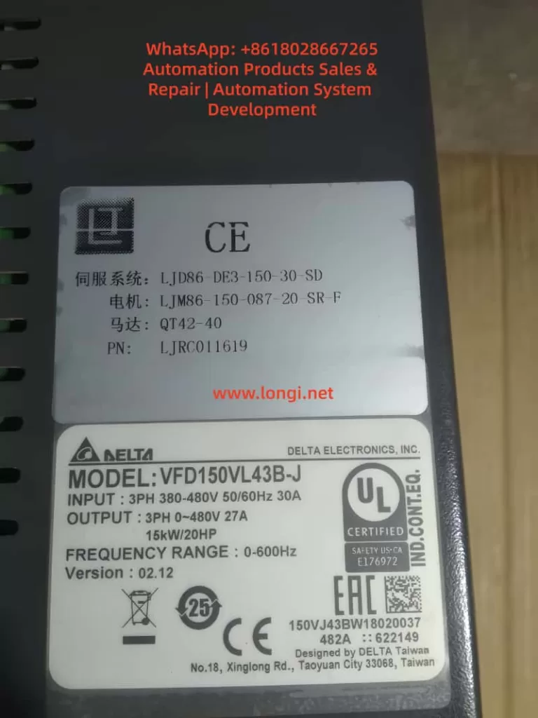
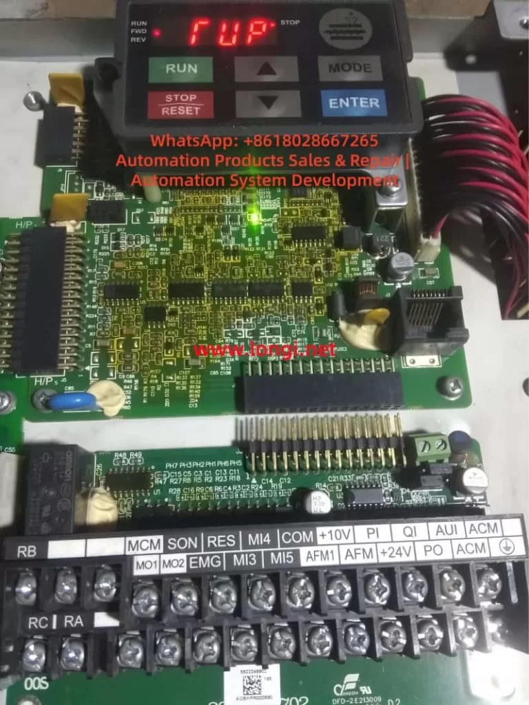
In modern elevator control systems, the Delta VFD-VL series inverter is widely used due to its high reliability, precision motor control, and mature elevator algorithms. However, many field engineers encounter abnormal panel indications such as “TUP” or “RUP”, which are not official Delta fault codes.
These abnormal characters often cause serious misjudgment — some users assume a main control failure or logic board damage, leading to unnecessary downtime and costly replacements.
Based on 200+ real maintenance cases, this article analyzes the display system architecture, segment-drive principles, and communication mechanisms of the VFD-VL series, and provides a systematic, engineering-grade troubleshooting methodology.
1. Technical Background: Display Architecture of Delta VFD-VL Series
1.1 Display Hardware Structure
The VFD-VL operator panel typically consists of:
Segment driver IC Examples: HT1621, TM1637, or similar LED driver chips Converts MCU data into segment and digit control signals.
7-segment LED display array Usually 4–6 digits, capable of displaying numbers and letters (F, U, P, etc.)
Communication interface Commonly I²C or SPI bus connecting the main control board to the display PCB.
Power supply circuit Typically regulated 5V supply (7805 or DC-DC), current consumption 50–200mA.
1.2 Seven-Segment Display Logic
Each character is formed by turning on specific LED segments:
“F” → a, e, f, g
“U” → b, c, d, e, f
“P” → a, b, e, f, g
Display distortion mechanism:
If one segment is falsely activated or missing:
“F” may appear as “T”
“U” may appear as “P”
Random combinations like “TUP” or “RUP” can occur.
This proves that TUP/RUP are not system alarms, but segment-mapping errors.
2. Core Conclusion: “TUP / RUP” Are NOT Real Fault Codes
According to the official Delta VFD-VL User Manual (2023), all inverter faults follow the “Fxxx” structure, such as:
F001 – Overcurrent
F002 – Overvoltage
F003 – Undervoltage
F004 – Overload
👉 “TUP” and “RUP” do not exist in any official fault table. They are caused by display distortion or communication errors.
3. Root Causes: Four Technical Categories
3.1 Hardware Layer – Segment Driver or LED Failure
3.1.1 Segment driver IC damage
Example: HT1621 SEG-B pin shorted high → “F” displayed as “T”.
Causes:
Internal logic breakdown
Moisture corrosion
Solder fatigue or ESD damage
3.1.2 LED aging
Blackened segments, brightness loss, internal open circuits.
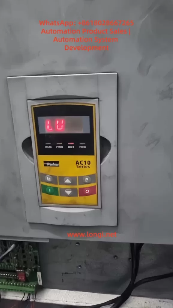
In the field of modern industrial automation, Variable Frequency Drives (VFDs) serve as the core equipment for motor control, and their stable operation directly impacts production efficiency and equipment lifespan. The Parker AC10 series inverter is renowned for its simplicity, reliability, and cost-effectiveness, widely used in applications such as fans, pumps, and conveyors. However, the LU fault code (Under-Voltage Protection) is one of the most common issues in this series, often causing equipment downtime. This article begins with the fundamental principles of inverters, provides a detailed analysis of the specifications and internal structure of the Parker AC10 series, and delves into the causes, diagnostic methods, and resolution strategies for LU faults. Through real case studies and preventive maintenance recommendations, it offers comprehensive technical guidance to help engineers solve problems efficiently. The article emphasizes safe operation and parameter optimization in practical application scenarios, aiming to enhance VFD maintenance standards.
Introduction
With the advancement of Industry 4.0, the role of inverters in energy saving, emission reduction, and precision control has become increasingly prominent. According to data from the International Energy Agency (IEA), motor systems consume approximately 46% of the world’s electricity, and inverters can save 20%-30% of this energy. As a global leader in motion and control technology, Parker Hannifin’s AC10 series inverter stands out for its compact design and user-friendly interface. However, in actual operation, faults are inevitable. Among them, the LU fault code is one of the most common protection mechanisms, representing under-voltage protection.
The occurrence of an LU fault usually stems from abnormal input voltage; if not addressed promptly, it can trigger chain reactions such as motor overheating or system collapse. Based on Parker’s official manuals, technical literature, and field experience, this article systematically expounds on the diagnosis and troubleshooting of LU faults. The structure includes inverter fundamentals, an overview of the AC10 series, fault details, cause analysis, diagnostic steps, case studies, preventive measures, and advanced topics. Through a logically rigorous narrative, it ensures readers can fully grasp the relevant knowledge from theory to practice.
Inverter Fundamentals
Definition and Working Principle of Inverters
An inverter is a power electronic device used to control the speed and torque of an AC motor. It achieves flexible drive of the motor by changing the output voltage and frequency. The basic structure includes a rectifier unit, a filter unit, an inverter unit, and a control unit.
Rectifier Unit: Converts input AC power into DC power, typically using a diode bridge rectifier. For a three-phase input, the output DC voltage (DC Bus) is approximately 1.414 times the input line voltage. For example, with a 380V input, the DC Bus is approximately 537V.
Filter Unit: Uses large-capacity electrolytic capacitors to smooth the DC voltage and reduce ripple. Under-voltage faults are often related to this unit; if the capacitor ages or the input voltage is insufficient, the DC Bus voltage will drop below the threshold.
Inverter Unit: Uses power devices such as IGBTs or MOSFETs to invert the DC power into adjustable frequency AC power for output to the motor.
Control Unit: Based on a microprocessor, it implements algorithms such as vector control and V/F control. The Parker AC10 supports sensorless vector control, providing precise torque response.
The protection functions of an inverter are crucial, including Over-Current (OC), Over-Voltage (OE), Overload (OL), and Under-Voltage (LU). LU protection is a safety mechanism that triggers when the DC Bus voltage falls below a set threshold to prevent equipment damage caused by operation under low voltage.
Application of Inverters in Industry
In the manufacturing industry, inverters are widely used for constant pressure water supply, fan speed regulation, and conveyor belt control. For example, in the textile industry, the AC10 can precisely control the speed of a spinning machine to reduce yarn breakage. Under-voltage faults occur frequently in areas with unstable power grids, such as remote factories or during peak electricity usage periods, leading to production interruptions. Understanding the basic principles helps in quickly locating the problem.
Overview of the Parker AC10 Series
Product Specifications and Features
The Parker AC10 series is an economical compact inverter with a power range from 0.2kW to 180kW (IP20 protection level) or 0.4kW to 90kW (IP66). It supports single-phase 230V, three-phase 230V, or 380-480V input voltage, with an output frequency of 0-400Hz. Key specifications include:
Parameter
Specification Description
Input Voltage
3-phase 380-480V (+10%/-15%)
Output Power
0.2-180kW
Overload Capacity
150% for 1 minute, 180% for 2 seconds
Control Mode
V/F, Sensorless Vector
Protection Function
IP20/IP66, Built-in EMC Filter
Interface
RS485 Modbus, Keypad Display
The AC10 adopts a modular design, with internal circuits including a power board, a control board, and a drive board. The power board is responsible for rectification and filtering, while the control board processes signals and parameters. Features include a built-in PID controller, auto-tuning, and display of up to 15 fault codes.
Internal Circuit Structure
The internal circuit of the AC10 focuses on efficiency and reliability. The input passes through an EMI filter to a rectifier bridge (typically 6 diodes) to generate the DC Bus. Electrolytic capacitors (typically rated for 450V) store energy, and an IGBT module inverts the output. A voltage sampling circuit monitors the DC Bus in real-time; if it falls below the threshold (approximately 320-340V for 380V models), it triggers an LU fault.
A control chip (such as the STM32 series) processes the fault logic. Common components on the power board include relays (HF105F), transformers, and resistor voltage divider networks. Loose connections often occur between these components, causing intermittent under-voltage.
Detailed Explanation of LU Fault Code
Meaning of the LU Code
In the Parker AC10 series, LU stands for “Low Voltage” or “Under Voltage,” i.e., under-voltage protection. When the inverter detects that the input voltage or DC Bus voltage is below the safety threshold, it displays LU and stops output. This is an active protection mechanism to avoid IGBT damage or motor loss of control when operating under low voltage.
According to the manual, the LU trigger threshold is usually 85%-90% of the input voltage. For example, in a 380V system, the threshold is approximately 320V. The fault code is displayed on the LED panel, accompanied by a buzzer or flashing indicator light.
Distinction from Other Faults
LU is different from Over-Voltage (OE) or Phase Loss (PF1). OE is caused by a high DC Bus, often due to regenerative energy; PF1 is caused by a missing input phase, leading to imbalance. LU focuses specifically on low voltage and is usually not accompanied by current abnormalities.
Common Cause Analysis
The causes of LU faults are diverse and can be divided into external and internal factors. Based on industry experience and literature, the following are common causes ranked by probability:
Input Power Supply Voltage Too Low (Most Common, ~60%) Grid fluctuations, peak loads, or long-distance transmission cause voltage drops. Both steady-state under-voltage (e.g., below 380V) and instantaneous sags can trigger it. The International Electrotechnical Commission (IEC) standard defines a voltage sag as a voltage drop below 90% lasting 10ms to 1 minute.
Power Connection Issues (~25%) Loose terminals, oxidized cables, or poor contact cause intermittent voltage drops. In user cases, loose wires on the power board fall into this category. Loose connections increase impedance, leading to a reduction in effective voltage.
Input Phase Loss or Imbalance (~10%) A broken wire in one phase or a blown fuse causes unstable rectifier output. The AC10 may report LU first and then switch to PF1.
Internal Component Failure (~5%) Aging of electrolytic capacitors (capacity attenuates by 20% after 5 years of use), damage to the rectifier bridge, or offset in the voltage sampling circuit. High-temperature environments accelerate aging.
Incorrect Parameter Settings The under-voltage threshold (P07.XX parameter) is set too high, or the input voltage range is set incorrectly.
Other rare causes include electromagnetic interference or load-side feedback, but the probability is low.
Diagnosis and Troubleshooting Steps
Diagnosing an LU fault requires a systematic approach, ensuring safety (de-energized operation). The following is a step-by-step guide:
Step 1: Initial Inspection and Reset
Observe the Panel: Confirm the LU code and record accompanying symptoms (e.g., motor not turning).
Reset: Press the STOP/RESET key. If it reappears immediately, the problem is persistent; if it recovers, it may have been a transient sag.
Step 2: Measure Input Voltage
Use a digital multimeter (e.g., Fluke) to measure the three-phase line voltages (L1-L2, L2-L3, L3-L1). Normal values should be within 380-480V ±10%.
If low: Check the power grid, transformer, or upstream switches. Add a voltage stabilizer or compensation capacitor.
Measure DC Bus: After power-off and discharging, connect probes to the P+ and N- terminals. Normal value is around 565V (as per user photos).
Step 3: Check Connections and Wiring
Inspect input terminals, cables, and contactors. Tighten screws and clean oxidation.
Test Continuity: Use the ohmmeter range to check inter-phase impedance; there should be no open circuit.
Step 4: Internal Inspection
Open the unit and inspect the power board: check for capacitor bulging, burn marks, or loose wires (as in the user case).
If capacitor is faulty: Replace with the same specification (e.g., 330μF 450V).
Step 5: Parameter Verification
Enter the menu (press M key): Check P07.02 (DC Bus voltage) and P00.11 (input voltage setting). Restore factory defaults if necessary.
Step 6: Test Run
Connect to a backup power source for testing. If normal, confirm an external issue; otherwise, send for repair.
Throughout the process, wear insulated gloves and avoid live operations.
Case Studies
Analysis of a Real Fault Case
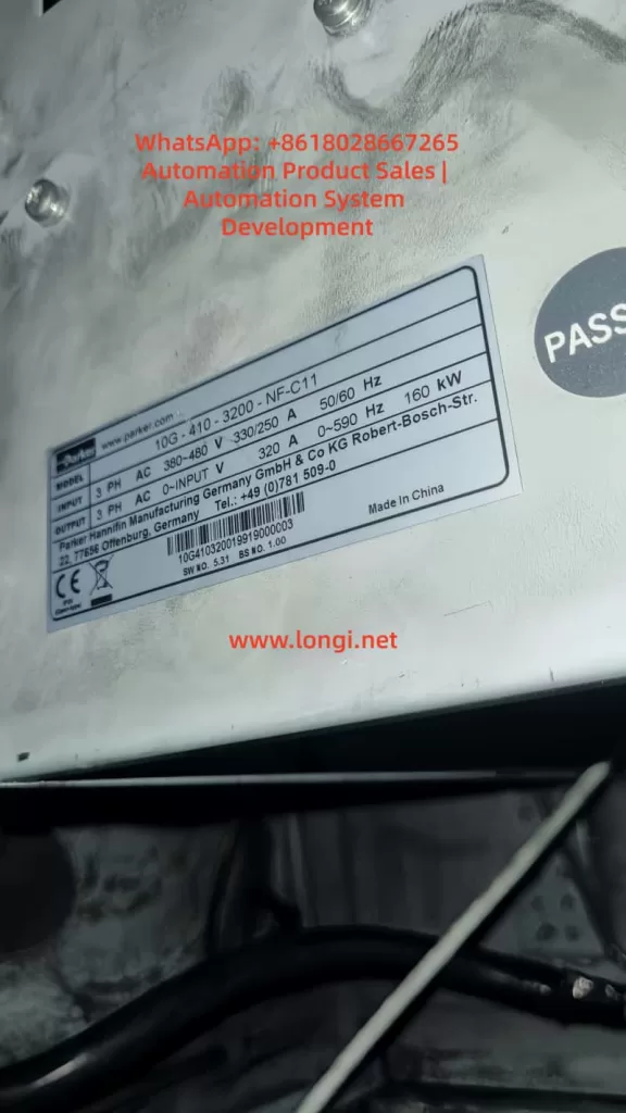
In a factory’s conveying system using a Parker AC10 5.5kW model (Model 10G-43-0120-BF), an LU fault suddenly appeared. Initial inspection showed the input voltage was normal (approx. 400V), but the DC Bus was only 565V (below normal).
Upon further disassembly, a wire connecting the rectifier bridge on the power board was found to be loose (see user photo). The looseness increased contact resistance, causing an instantaneous voltage drop that triggered the LU. After re-plugging and securing the wire, the equipment returned to normal.
Analysis: Vibration environments cause wires to loosen, which is a connection issue. Prevention: Secure with cable ties.
This case highlights the importance of measurement and visual inspection, saving the cost of replacing components.
Simulated Case: Grid Fluctuation
Assume a water pump application where a grid sag causes an LU fault. Solution: Install a UPS or Dynamic Voltage Restorer (DVR), costing approximately $2000, but avoiding downtime losses.
Prevention and Maintenance Strategies
Prevention is better than cure. The following is a maintenance guide for the AC10:
Regular Maintenance Schedule
Monthly: Clean dust and check terminal tightness.
Quarterly: Measure voltage and test capacitor capacity (using an LCR meter).
Yearly: Comprehensive overhaul and software upgrade.
Environmental Optimization
Install in a ventilated cabinet to avoid high temperatures (>40°C).
Use EMC filters to reduce interference.
Parameter Optimization
Set P00.13 to auto-restart to reduce manual intervention.
Monitor Logs: The AC10 supports fault history recording (P14.XX).
Implementing these measures can reduce the fault rate by 30%.
Advanced Topics: Parameter Adjustment and Circuit Analysis
Parameter Deep Dive
The AC10 parameter groups include P00 (Basic), P01 (Motor), and P07 (Monitoring). Under-voltage related parameters: P07.01 (Input Voltage), P11.08 (Under-voltage Threshold). Adjusting the threshold requires caution to avoid false protection.
In-depth Internal Circuit Analysis
Power Board Circuit: The input passes through a fuse to the rectifier bridge. Behind the bridge, capacitors and discharge resistors are connected in parallel. Sampling is performed via a voltage divider resistor to the ADC. When a fault occurs, the MCU compares the value and triggers an interrupt.
For maintenance, it is recommended to use an oscilloscope to observe ripple (normal <5%). If an IGBT fails, it may cause a chain reaction LU fault.
IoT Integration Monitoring
Modern Trend: Connect RS485 to a SCADA system for real-time voltage monitoring. Parker provides software tools such as Drive System Explorer.
Conclusion
While the LU fault in the Parker AC10 series is common, it can be efficiently resolved through systematic diagnosis. This article covers the full spectrum of knowledge from basics to advanced topics. The key takeaway is: Safety First, Prevention Oriented. In the future, with the development of intelligent diagnostic technologies, VFD faults will become easier to predict. I hope this article helps you master the techniques and improve efficiency.
Abstract The ABB ACS611 series inverter is a versatile product widely used in industrial drives for applications like fans, pumps, and compressors. One common fault in this series is the “LINE CONV” fault (Line Converter Fault), which is one of the main reasons for frequent shutdowns. This fault involves the rectification topology, power system, and control circuits, and if not promptly addressed, it can lead to rectifier module damage, DC bus instability, and even safety incidents. This article begins by explaining the rectification principle of the ACS611 inverter and systematically analyzes the “LINE CONV” fault’s triggering mechanism, core causes, and troubleshooting process, providing practical case studies and preventive measures for engineers.
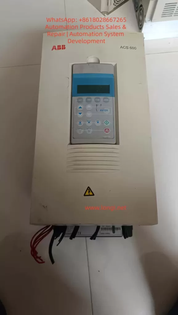
1. Introduction The ABB ACS611 series inverter, designed for medium to large loads, covers power ratings from 5.5 to 560 kW (approximately 7 to 700 kVA). It supports various topologies such as diode rectification and AFE (Active Front End), with the 70 kVA model commonly used for medium-sized fans, pumps, and compressors. This inverter features energy feedback and power factor correction (PF ≥ 0.98), making it a core component of industrial energy-saving retrofits.
However, during long-term operation, the “LINE CONV” fault (Fault Code: LINE CONV FAULT) becomes a frequent issue in the ACS611 series. According to ABB’s service data, this fault accounts for approximately 18% of the ACS611 inverter’s shutdowns, primarily due to abnormal rectifier unit scenarios. This article breaks down the fault from principle explanation to troubleshooting, offering engineers a step-by-step guide to quickly locate and resolve the issue.
2. ACS611 Rectification Topology and “LINE CONV” Fault Definition (a) ACS611 Rectification Topology The line converter (rectifier unit) is the “energy entry point” of the ACS611 inverter, responsible for converting AC input into DC bus voltage. The 70 kVA and higher models typically use the AFE (Active Front End) topology, which includes the following core components:
IGBT Modules: These act as the rectifier switches, using PWM control to achieve bidirectional energy flow (motor feedback energy can be fed back into the grid).
Pre-charging Circuit: Consisting of pre-charging resistors (PTC/coil resistors) and a pre-charging contactor, it limits inrush current when powering up.
DC Bus Capacitors: These buffer the rectified DC voltage, stabilizing the input to the inverter unit.
Control Circuit: Includes voltage/current sensors, driver boards, and CPU boards, implementing closed-loop control of the rectifier unit.
Compared to traditional diode rectifiers, AFE topologies offer the advantages of energy feedback and power factor correction, but they are more complex, with more potential fault points (e.g., IGBT drivers, pre-charging circuits).
(b) “LINE CONV” Fault Official Definition According to ABB’s ACS611 Fault Code Manual, the “LINE CONV” fault is triggered when the rectifier unit fails to convert AC to DC, which can be caused by one of the following issues:
The rectifier unit detects abnormal conversion from AC input to DC bus voltage, leading to an unstable DC bus voltage.
Rectifier modules (diodes/IGBTs) experience short circuits, open circuits, or driver signal loss.
The typical symptoms of this fault include:
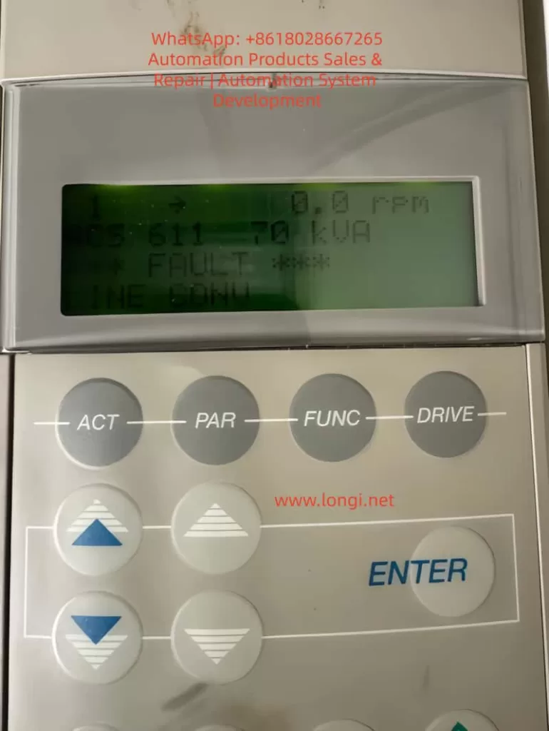
The inverter panel displays “*** FAULT ***” followed by “LINE CONV.”
Abnormal DC bus voltage (overvoltage, undervoltage, or fluctuation).
Rectifier current exceeds the rated value (e.g., 120% rated current).
Pre-charging failure (unable to establish DC bus voltage during startup).
3. Core Cause Analysis of “LINE CONV” Fault The essence of the “LINE CONV” fault is the inability of the rectifier unit to complete the AC-to-DC conversion. The causes can be categorized into four main areas: external power supply issues, hardware damage, control abnormalities, and environmental factors, as detailed below:
(a) External Power Supply Issues (Approximately 35%) The power supply is the “energy source” for the rectifier unit, and any issues with the power supply can trigger the fault:
Phase Loss: If one of the three-phase inputs is disconnected (e.g., fuse blown or contactor contacts burned), the current distribution is uneven, potentially causing overheating and damage.
Voltage Imbalance: If the three-phase voltage imbalance exceeds 5%, rectifier current peaks can increase by 2-3 times, accelerating aging.
Overvoltage/Undervoltage: If the input voltage exceeds ±10% of the rated value, overvoltage can damage rectifier modules, while undervoltage prevents the DC bus from being established.
Harmonic Interference: Large amounts of harmonics in the power supply can trigger false rectifier module actions.
(b) Rectifier Module Damage (Approximately 28%) Rectifier module damage is a core hardware issue for the “LINE CONV” fault:
Diode Rectifier Bridge:
Short Circuit: Both forward and reverse directions conduct (measuring 0Ω between input L1 and output + terminal).
Open Circuit: Both directions are blocked (measuring “OL” between input and output), causing DC bus voltage fluctuation.
AFE IGBT Modules:
Gate (G) Damage: Resistance between gate and emitter is lower than expected (<1kΩ, indicating gate damage).
Collector-Emitter (C-E) Short Circuit: Both directions conduct, triggering overcurrent protection.
(c) Pre-charging Circuit Failure (Approximately 20%) The pre-charging circuit limits inrush current during startup. Failures in this circuit can directly cause “LINE CONV” faults:
Pre-charging Resistor Damage: Overuse or insufficient power rating of the resistor leads to overheating and failure (e.g., 500W resistor used instead of 200W).
Pre-charging Contactor Failure: Issues such as open circuits or burnt contact points prevent the pre-charging circuit from engaging, causing excessive inrush current.
(d) DC Bus Issues (Approximately 12%) The DC bus stabilizes the energy between the rectifier and inverter units. Abnormalities here can affect the rectifier unit’s operation:
Overvoltage: A sudden increase in power supply voltage or failure to release motor feedback energy leads to an overvoltage condition.
Undervoltage: Drop in input voltage or excessive load causes undervoltage.
Ripple Issues: Aging DC bus capacitors increase ripple, causing instability in the rectifier unit.
(e) Control Circuit Failures (Approximately 5%) The control circuit, the “brain” of the rectifier unit, can cause false alarms or improper control if damaged:
Sampling Circuit Failure: Voltage sensor damage can cause incorrect voltage readings.
Driver Circuit Failure: Failure in the IGBT driver board causes improper switching of IGBTs.
CPU Board Failure: If the CPU board malfunctions, the rectifier unit may not receive proper start-up instructions.
(f) Environmental and Cooling Issues (Minimal Impact) Though not a primary cause, environmental and cooling issues can contribute to failure:
Fan Failure: Fans malfunctioning due to bearing issues lead to overheating of rectifier modules.
Excessive Dust: Accumulated dust on heat sinks reduces cooling efficiency.
High Ambient Temperature: High installation temperatures can hinder module cooling.
4. Troubleshooting and Resolution Methods The troubleshooting process begins with safety preparation and proceeds through a step-by-step diagnosis from external to internal causes:
Step 1: Check Input Power Use a multimeter to measure the three-phase voltage, ensuring no phase loss or imbalance.
Step 2: Inspect Rectifier Modules Test diodes and IGBT modules for shorts or open circuits, replacing faulty components as necessary.
Step 3: Inspect Pre-charging Circuit Test the pre-charging resistor and contactor for failure, replacing faulty components to restore functionality.
Step 4: Inspect DC Bus Use a high-voltage probe to measure DC bus voltage, checking for overvoltage, undervoltage, and excessive ripple.
Step 5: Inspect Control Circuits Use Drive Composer software to analyze fault history, checking sensors, IGBT drivers, and CPU boards for malfunctions.
Step 6: Inspect Cooling and Environment Check for fan operation, clean dust from heat sinks, and monitor ambient temperatures to ensure proper cooling.
5. Case Studies
Case 1: Chemical Plant ACS611-70kVA Inverter “LINE CONV” Fault
Symptoms: Inverter suddenly trips with “LINE CONV” error and 0V DC bus voltage.
Diagnosis: Short circuit in the diode rectifier bridge.
Solution: Replaced the damaged rectifier bridge (ABB 6SY7000-0AB42).
Case 2: Water Plant ACS611-70kVA Inverter “LINE CONV” Fault
Symptoms: Pre-charging failure during startup.
Diagnosis: Open circuit in pre-charging contactor.
Solution: Replaced the pre-charging contactor (ABB A145-30-11).
6. Preventive Measures
Regularly maintain power supply, rectifier modules, pre-charging circuits, and cooling systems to avoid “LINE CONV” faults.
Use Drive Composer to monitor system performance and detect early signs of trouble.
7. Conclusion The “LINE CONV” fault in the ABB ACS611 inverter involves complex interactions between the power supply, hardware, control circuits, and environment. Engineers can effectively troubleshoot and resolve these faults by following a systematic approach and utilizing diagnostic tools. Regular preventive maintenance is crucial to avoid such failures and ensure the long-term reliability of industrial drive systems.
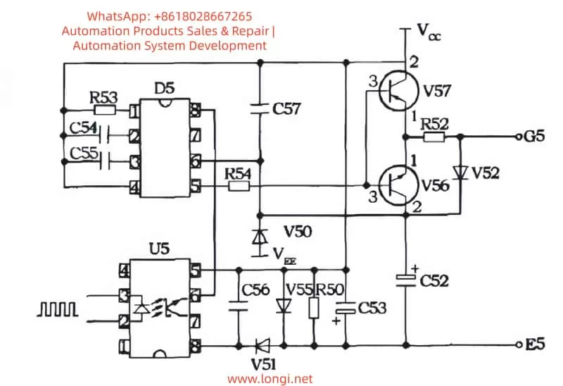
With the continuous advancements in industrial automation, precise motor control has become a critical application requirement, especially in CNC systems, servo drivers, and other high-performance motor control devices. The Siemens 6SN1123 – 1A00-0EA1 drive, as a motor driver, plays a crucial role in various industrial automation systems. By employing IGBT (Insulated Gate Bipolar Transistor) driver circuits, it ensures stable motor performance even under varying load conditions.
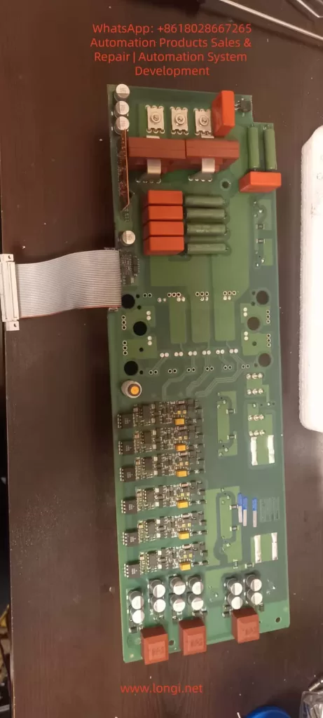
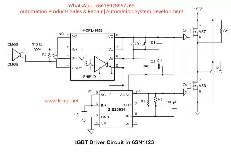
In this article, we will provide a detailed analysis of the IGBT driver circuit used in the 6SN1123 drive, focusing on the SIE20034 gate driver, HCPL-1458 optocoupler, and essential components like IGBT transistors, resistors, and capacitors. We will explain their function in creating an electrically isolated H-bridge configuration, discuss how the system works, and explore troubleshooting methods for common failures in the drive system.
1. Overview of the 6SN1123 Drive
The Siemens 6SN1123 – 1A00-0EA1 drive is a high-performance variable frequency drive (VFD), widely used in various motor control applications. Its key features include precise motor control, efficient power conversion, and robust protection mechanisms.
This drive uses a combination of the SIE20034 gate driver and IGBT modules to control the motor efficiently. The HCPL-1458 optocoupler is used for signal isolation, ensuring that the low-voltage control circuit remains protected from high-voltage components. Through an intricate circuit design, the 6SN1123 ensures smooth motor operation while maintaining system stability.
2. Working Principle of the IGBT Driver Circuit
The IGBT driver circuit is the heart of the 6SN1123 drive, responsible for controlling the current through the IGBT modules, which in turn control the motor’s speed and torque. The IGBT (Insulated Gate Bipolar Transistor) is a power semiconductor widely used in motor drives and power electronics due to its high efficiency and fast switching capabilities.
2.1 Key Components in the Driver Circuit
SIE20034 Gate Driver The SIE20034 is an efficient IGBT driver responsible for controlling the gate voltage of the IGBT modules. This driver chip receives signals from the HCPL-1458 optocoupler and uses them to switch the IGBT transistors on and off, thus controlling the current flowing through the motor.
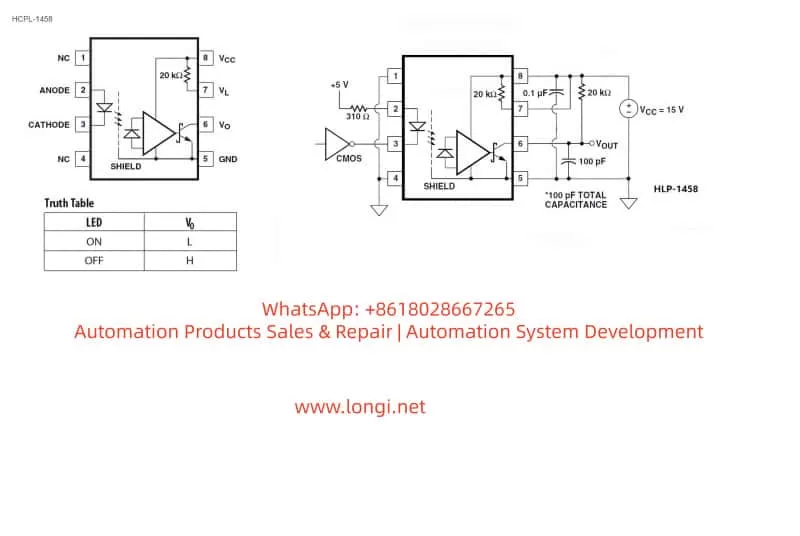
HCPL-1458 Optocoupler The HCPL-1458 optocoupler plays a vital role in isolating the high-voltage section of the circuit from the low-voltage control section. It works by converting the input electrical signal into an optical signal and then back into an electrical signal at the output, maintaining electrical isolation between the control and power circuits.
IGBT Modules IGBTs (Insulated Gate Bipolar Transistors) are key to switching high currents and voltages in motor drives. They combine the best features of MOSFETs and BJTs, providing fast switching speeds and low saturation voltage, making them ideal for use in high-power applications like motor drives.
Resistors and Capacitors Resistors and capacitors are used in the IGBT driver circuit for signal conditioning and power stabilization. Capacitors smooth out voltage fluctuations, ensuring stable operation, while resistors limit current and set signal levels for the IGBT driver.
2.2 Driver Circuit Workflow
Signal Input: The control signal, often from a CMOS signal source, is fed into the circuit. The signal is first passed through the HCPL-1458 optocoupler for isolation, ensuring that the high-voltage IGBT circuit does not interfere with the low-voltage control circuitry.
Signal Amplification: The optocoupler converts the input signal into an optical signal and then feeds it into the SIE20034 gate driver. The gate driver amplifies the signal and drives the IGBT gates to control the switching behavior of the IGBT transistors.
IGBT Switching: The IGBTs switch the current to the motor based on the gate voltage provided by the SIE20034 driver. The IGBT modules control the speed, torque, and direction of the motor by regulating the current flow through the motor windings.
Current Monitoring and Protection: The driver circuit includes overcurrent protection to prevent damage to the IGBT modules or the motor in case of a short circuit or overload condition. The fuse and current sensors help to protect the circuit by disconnecting in case of excessive current.
3. Troubleshooting the IGBT Driver Circuit
3.1 Common Failures
Overheating Overheating is a common issue in IGBT driver circuits, often caused by excessive current or inadequate heat dissipation. If the IGBT modules or the SIE20034 driver gets too hot, they may fail or trigger fault alarms like E104.
Signal Failures A failure in the HCPL-1458 optocoupler or the SIE20034 driver can result in distorted or missing control signals, causing the IGBT modules to malfunction. This may lead to erratic motor behavior or complete motor shutdown.
Overcurrent Protection Failures If the overcurrent protection fails, the circuit might experience excessive current, causing damage to the IGBT modules or the motor. A failure in the current sensors or fuse can result in a failure to detect high current, leading to catastrophic failure.
3.2 Troubleshooting Methods
Check the Cooling System: Ensure that the heat dissipation system (such as fans and heat sinks) is functioning properly. If necessary, add extra cooling mechanisms to prevent overheating of the IGBT modules.
Verify the Control Signals: Use an oscilloscope to inspect the signals coming from the HCPL-1458 and SIE20034. Ensure that the signals are not distorted and are within the correct voltage ranges. If there is any signal distortion, replace the damaged components.
Inspect the Protection Circuits: Check the fuse, current sensors, and other protective components. Make sure the overcurrent protection circuits are working correctly. If any of these components are damaged, replace them immediately to avoid further damage to the system.
4. Conclusion
The IGBT driver circuit in the 6SN1123 – 1A00-0EA1 drive plays a crucial role in controlling the motor’s performance. Through the combination of the SIE20034 gate driver, HCPL-1458 optocoupler, and IGBT modules, this circuit enables smooth motor control, providing efficient and precise operation even under varying load conditions.
By understanding the working principles of the IGBT driver circuit, we can ensure its proper functioning and troubleshoot any issues that may arise. Proper maintenance, regular inspections, and understanding common failures can significantly extend the life of the drive system and improve its overall performance.
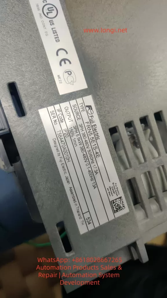
In the field of industrial automation, variable frequency drives (VFDs) are critical components used for controlling motor speed, ensuring efficient and reliable operations. However, due to their complex environment and diverse components, VFDs often encounter failures that impact the continuity and stability of production processes. One of the key components prone to failure in VFDs is the DC bus pre-charge resistor. Specifically, in the Fuji FRENIC-E1S series inverter, this component is highly susceptible to damage from excessive heat, overloads, and other operating stresses.
This article focuses on the failure of the DC bus pre-charge resistor in Fuji FRENIC-E1S inverters, analyzing its role, common causes of failure, diagnostic methods, and offering practical repair solutions. The goal is to help technicians and engineers better understand this critical component and equip them with effective methods for maintaining and restoring inverter functionality.
1. The Role of the DC Bus Pre-Charge Resistor in Variable Frequency Drives
1.1 The DC Bus Capacitor Charging Process Inverters, including the Fuji FRENIC-E1S, require DC bus capacitors to be charged upon startup. These capacitors are essential for storing energy in the DC bus and enabling smooth operation of the inverter. However, directly charging these capacitors can result in large inrush currents, which can damage both the power supply and other components of the inverter. This is where the pre-charge resistor comes into play.
1.2 Function and Design of the Pre-Charge Resistor The primary function of the pre-charge resistor is to limit inrush current when the inverter is powered on. It allows the DC bus capacitors to charge slowly by dissipating the charging current over a longer period. Once the charging process is complete, the resistor is bypassed by a relay or thyristor (SCR), thus minimizing power loss and optimizing efficiency.
In the Fuji FRENIC-E1S, the pre-charge resistor helps ensure that the DC bus voltage increases gradually and stabilizes at the designed value. This process prevents sudden large currents, which could damage sensitive components of the inverter.
2. Common Causes of DC Bus Pre-Charge Resistor Failure
2.1 Causes of Pre-Charge Resistor Failure The failure of the pre-charge resistor is typically caused by the following factors:
Overload of Current: When the inverter experiences frequent starts or the bus capacitors have a larger capacity, the pre-charge resistor is subjected to prolonged high currents, which may lead to overheating and failure.
Faulty Relay or Thyristor: If the relay or thyristor used to bypass the pre-charge resistor fails, the resistor will be subjected to continuous high power, eventually causing it to overheat and burn out.
Power Fluctuations or Missing Phases: Inverters are sensitive to fluctuations in the input power supply. If the power supply is unstable or the inverter operates with missing phases, the DC bus capacitors may not charge properly, placing excessive strain on the pre-charge resistor.
Aging of Bus Capacitors: As the bus capacitors age, their charging characteristics change, leading to longer pre-charge times. This increased load on the pre-charge resistor can eventually cause it to burn out.
High Ambient Temperature: In high-temperature environments, the resistor’s heat dissipation capacity may be compromised, leading to overheating and failure.
2.2 Symptoms of Pre-Charge Resistor Failure When the pre-charge resistor fails, the inverter often exhibits the following symptoms:
Inverter Fails to Start: Since the pre-charge resistor is responsible for the initial charging of the DC bus capacitors, a failed resistor prevents proper charging, and the inverter fails to start.
Alarms or Fault Codes: In some inverters, the failure of the pre-charge resistor triggers alarms or fault codes such as overcurrent or startup failure.
Power Instability: A burned pre-charge resistor can cause instability in the power supply, leading to frequent shutdowns or restarts of the inverter.
3. Diagnosing and Troubleshooting DC Bus Pre-Charge Resistor Failure
3.1 Fault Code Diagnosis Many inverters come equipped with a fault diagnostic system. When a failure occurs, the inverter will display a fault code indicating the issue. For example, in the Fuji FRENIC-E1S, a burned pre-charge resistor may trigger fault codes such as “Overcurrent” or “Startup Failure.” These codes can serve as initial clues for identifying the problem.
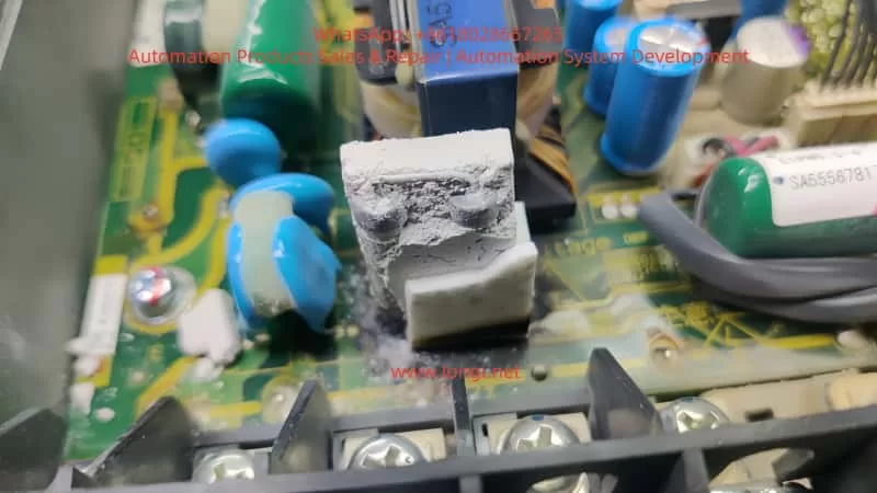
3.2 Visual Inspection of the Resistor A visual inspection can provide immediate insights into whether the pre-charge resistor has failed. Common signs of failure include:
Burnt marks or white powder on the surface of the resistor.
Cracked or damaged resistor leads.
Overheating signs such as melted or charred components around the resistor.
3.3 Measuring Resistor Value A multimeter can be used to measure the resistance of the pre-charge resistor. If the measured resistance deviates significantly from the nominal value (usually 22Ω to 27Ω), or if the resistor is open or shorted, it confirms the resistor is damaged.
4. Replacing and Repairing the DC Bus Pre-Charge Resistor
4.1 Preparation for Replacement Before replacing the pre-charge resistor, ensure that the inverter is powered off and completely cool. Open the inverter enclosure, disconnect the power supply, and prepare the necessary tools and replacement resistor.
4.2 Removing and Replacing the Resistor
Remove the Old Resistor: Use appropriate tools to remove the damaged resistor. Resistors are typically soldered onto the PCB, so use a desoldering pump or hot air rework station to carefully remove it.
Clean the PCB: After removing the old resistor, clean the PCB with electronic cleaner to remove any residue or burnt material, ensuring that the new resistor can be securely mounted.
Install the New Resistor: Choose a replacement resistor with the same specifications (typically 22Ω – 27Ω and 30W – 50W), and solder it into place on the PCB. Ensure that the solder joints are secure and free of cold solder connections.
4.3 Checking the Relay and Capacitors: After replacing the resistor, check the pre-charge relay and the DC bus capacitors:
Relay Test: Verify that the pre-charge relay operates correctly, switching from charging to bypass mode once the capacitors are sufficiently charged.
Capacitor Check: Measure the bus capacitor voltage and ESR (Equivalent Series Resistance) to ensure that the capacitors are not aging or damaged.
4.4 Testing the Inverter: After replacing the resistor, reconnect the power supply and power on the inverter. Observe if it starts up normally and check for any fault codes. If the inverter operates without issues, the problem has been resolved.
5. Preventive Measures and Maintenance Recommendations
5.1 Regular Inspection and Maintenance To prevent pre-charge resistor failure, regular maintenance of the inverter is essential. This includes periodic checks on the pre-charge resistor, relay, and bus capacitors. Cleaning the PCB, inspecting the resistor condition, and monitoring ambient temperature can help extend the life of the components.
5.2 Environmental Control Inverters should be installed in environments with suitable temperature and humidity levels. Avoid installing them in high-temperature or humid environments, as this can impact the resistor’s heat dissipation capability and lead to overheating.
5.3 Using High-Quality Components When selecting components for the inverter, use high-quality resistors and other electrical components. This ensures that the pre-charge resistor is capable of handling the required power and prevents premature failure.
6. Conclusion
The DC bus pre-charge resistor is a small but vital component in a variable frequency drive. Its failure can lead to significant issues such as startup failure and power instability. By understanding the role of the pre-charge resistor, diagnosing the causes of its failure, and following proper repair procedures, technicians can restore the inverter to full functionality. Regular maintenance and preventive measures are essential for ensuring the longevity and reliability of VFDs, minimizing downtime, and optimizing production processes.
For VFD operators and service providers, understanding the working principles and failure modes of key components like the pre-charge resistor is crucial for keeping the system running smoothly and preventing costly downtime.
The ZS100 series servo drives are developed by Zhejiang Zhengshun Electromechanical Co., Ltd. and are primarily used in servo pump control systems, widely applied in industries such as injection molding machines, hydraulic presses, and spinning machines. Known for their high reliability and stability, these drives support both Ver1.0 and Ver2.0 parameter versions and have a wide power range, allowing precise pressure and flow control.
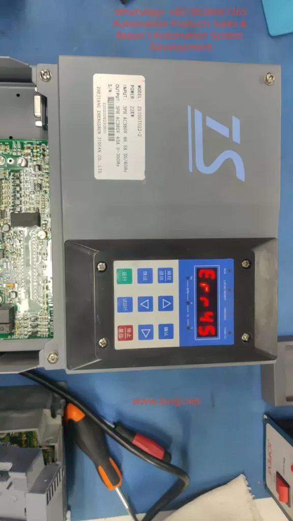
However, the ERR45 fault, which is a common motor temperature overheat alarm, can occur due to environmental factors, sensor issues, or abnormal loads, affecting the continuity of operations. This article delves into the causes, diagnostic methods, solutions, and preventive strategies of the ERR45 fault, combining manual guidance and industry practices to provide comprehensive technical reference for engineers to efficiently troubleshoot and optimize the system.
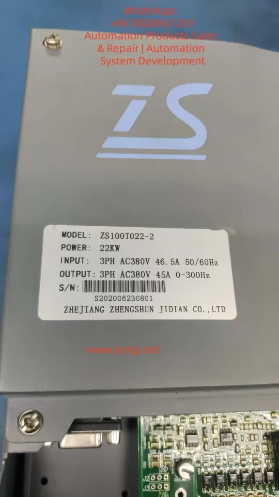
Key components of the ZS100 series include the servo drive, ZM permanent magnet synchronous motor, and ZB braking unit. The drive operates on a three-phase AC380V input with 0-300Hz variable frequency control, suitable for 22KW power models (e.g., ZS100T022-2). The ERR45 fault code specifically refers to the motor temperature sensor detecting abnormal high temperatures, usually accompanied by a protective shutdown. This fault is closely related to hardware connections, parameter settings, environmental adaptability, and system integration. A systematic analysis is required to explore the diagnostic logic.
2. Servo Drive Basic Principles and ZS100 Series Features
2.1 Working Principle of Servo Drive
Servo drives are key components in industrial automation, achieving precise control of motor position, speed, and torque through closed-loop control. The basic structure includes the power module, control unit, sensor interface, and communication module.
Power Module: Utilizes IGBT or MOSFET power devices to convert the AC power supply into PWM signals to drive the motor.
Control Unit: Based on DSP or MCU processors, executing PID algorithms to process feedback signals and ensure fast system response.
In servo pump applications, the ZS100 series drive adopts vector control mode and supports dual closed-loop pressure/flow regulation. Motor temperature monitoring is a core protection mechanism, utilizing PTC (positive temperature coefficient thermistor) or KTY (linear temperature sensor) to collect data. When the temperature exceeds the threshold (e.g., default 150°C), the drive triggers the ERR45 alarm and cuts off the output to prevent motor burnout. This reflects the safety redundancy design of the servo system but can also lead to false alarms, causing production downtime.
2.2 ZS100 Series Technical Specifications
Power Range: 7.5KW to 132KW
Current Parameters: Input current 46.5A (for 22KW model), output 45A
Frequency: Supports 50/60Hz input and 0-300Hz output
Version Features:
Ver1.0: Suitable for basic hydraulic control
Ver2.0: Enhanced jitter suppression and pressure overshoot optimization, with new P2 group gain adjustments and P3 group filtering settings
Motor Compatibility: ZM series permanent magnet synchronous motors, encoder resolution up to 2500ppr, supports RS485 Modbus communication
Installation and Cooling: Wall-mounted or cabinet-mounted, cooling reliant on the built-in fan
Peripheral Components: Recommended Schneider or ABB circuit breakers, contactors, and filters; ZB series braking units for energy feedback
2.3 Locating ERR45 Fault in the System
ERR45 is categorized under the temperature-related alarms in the drive fault diagnosis table, found in Chapter 4 of the manual.
Fault Definition: “Motor temperature too high,” possibly caused by overheating, sensor disconnection, or short circuit.
Alarm Manifestation: Display “ERR45” on the screen, accompanied by a beeping sound or flashing LED indicators.
System Status: Automatically enters protection mode, output is cut off, and manual reset or power restart is required.
High-incidence Scenarios: Molding stage of injection molding machines, pressurization process in hydraulic presses.
Statistical Data: Approximately 15%-20% of servo faults in industrial settings are temperature-related, with ERR45 being a significant portion.
3. Causes of ERR45 Fault
3.1 Hardware Factors
The core of motor overheating is the disruption of thermal balance. The ZM servo motor, with an IP65 protection rating, has an integrated temperature sensor. However, long-term operation with dust accumulation or blocked cooling ducts can reduce cooling efficiency.
Fan Failure: Insufficient fan speed, bearing wear, or power interruption in the drive or motor fan. Check J2 fan interface and P0.15 fan control parameters.
Sensor Issues: Loose connections, cable damage, or short circuits in the temperature sensor (PTC/KTY). PG flat cables (encoder cables) carrying temperature signals can cause false alarms if improperly connected.
Environmental Impact: Installation environments with temperatures above 40°C, humidity > 90%, or poor ventilation. The ZS100 series requires an operating environment between -10°C and +50°C, and exceeding this range can increase the sensitivity of thermosensitive components.
3.2 Software and Parameter Factors
Incorrect parameter settings are a hidden cause.
Version Differences: In Ver1.0, if motor parameters (e.g., P1.04 rated power, P1.05 rated current) are not self-learned, it can cause excessive current, indirectly increasing temperature. Ver2.0 adds P4 group temperature protection threshold adjustment (default 150°C, adjustable from 120°C to 180°C).
PID Parameters: Insufficient optimization of P2.01 proportional gain and P2.02 integral time can lead to system oscillations, increasing motor load.
Communication Factors: In Modbus communication mode, excessive command frequency from the host machine can amplify thermal effects.
3.3 Load and Application Factors
In servo pump systems, ERR45 is often linked to load fluctuations.
Hydraulic Characteristics: The motor torque demand during continuous suction or discharge of hydraulic fluid can reach 150% of the rated value. High oil temperatures (>60°C) cause motor efficiency degradation, leading to increased thermal loss.
Multi-pump Configuration: Master-slave synchronization offset can indirectly overload a single motor.
Power Supply and Braking: Power fluctuations (input voltage <342V or >418V) or improper braking resistor selection (ZB unit power matching the drive’s power by >1.2 times) can exacerbate bus voltage instability, affecting motor cooling.
3.4 Fault Statistics and Pattern Recognition
Based on industry data:
Initial Installation and Debugging Period: Highest occurrence (about 30%), often due to cable connection errors.
Seasonal: High-temperature environments lead to frequent alarms in summer.
Predictive Methods: Using data recording functions (L0 group monitoring parameters, e.g., L0.11 temperature sensor values), trend analysis can predict faults.
4. Diagnostic Methods and Steps
4.1 Initial Checks
When the fault occurs, record the display screen information first: ERR45 code, current frequency (d0.00), current (d0.01), and temperature values (d0.10).
Follow the manual flowchart:
Power off and check external appearance: Ensure the motor has no burnt smell, and the fan is working correctly.
Measure temperature: Use an infrared thermometer to verify the motor shell temperature. If <100°C, it may be a false alarm.
4.2 Sensor and Connection Diagnosis
Focus on troubleshooting the temperature sensor:
Interface check: Inspect CN1 or J3 interfaces to ensure the PG cable is intact.
Resistance measurement: Use a multimeter to measure resistance (PTC normal >100Ω, KTY approximately 1kΩ at 25°C).
Parameter verification: Enter P1 group and perform motor self-learning (P1.00=1), observe temperature feedback.
4.3 Electrical and Parameter Diagnosis
Use an oscilloscope to monitor the output waveform and check for current harmonics. If abnormalities are found, adjust P3 filtering parameters.
Measure the three-phase balance on the power side. A deviation of >3% needs rectification.
For Ver2.0, use the new diagnostic tools (e.g., P5.01 fault log query) to analyze historical records.
4.4 Advanced Diagnostic Tools
Integrate with host software via RS485 to read internal variables (communication address defined in Appendix K, e.g., 0x2000 for fault codes).
Use MATLAB or dedicated simulation software to model the load and verify the temperature model.
In multi-pump systems, check CAN communication (Chapter 9 case) to ensure synchronization without delay.
5. Solutions and Repair
5.1 Immediate Repairs
Reset Method: Follow the manual to press the STOP/RESET button or power off for 10s and restart. If the fault reoccurs, enter fault mode.
Hardware Replacement: Replace the fan with a same-model part. For short-circuited sensors, cut and insulate the wiring.
Parameter Optimization: Reduce P2.01 gain by 10%, increase P2.02 integral time to 0.5s to reduce oscillation-related heat.
5.2 System-Level Optimization
Upgrade to Ver2.0 for enhanced suppression capabilities.
Add external heat exchangers or water cooling systems for high-temperature environments.
In hydraulic control, use DI schemes (Chapter 9) to adjust speed thresholds and avoid peak loads.
5.3 Case Applications
Injection Molding Case: ERR45 caused by pump blockage. Fault eliminated by cleaning the filter and adjusting P9 high-pressure lock mode parameters.
Spinning Machine CAN Application: Communication delay led to overheating. System stabilized by optimizing PD group parameters.
Direct Drive Screw Solution: Matching the braking resistor (Manual Section 6.6) improved energy efficiency by 20%.
6. Preventive Measures and Maintenance Strategies
6.1 Daily Maintenance
Clean the cooling ducts regularly and check cables quarterly.
Use environment monitoring devices to ensure temperature <40°C.
Back up parameters using Modbus for quick recovery after faults.
6.2 Predictive Maintenance
Integrate IoT modules for real-time temperature monitoring.
Set early warning thresholds (e.g., 130°C) for preemptive action.
Train operators to recognize early signs (e.g., unusual noise or power drop).
6.3 Upgrades and Compatibility
Consider upgrading to the ZS200 series, which offers richer Ver2.0 parameters. It is compatible with older systems, with only parameter extensions required.
7. Advanced Topics: The Role of Temperature Management in Servo Systems
7.1 Thermal Modeling and Simulation
Motor thermal models are based on thermal resistance-capacitance networks. The temperature T satisfies the formula:dtdT=Ploss−QcoolCth
Where Ploss represents the loss power and Qcool is the cooling heat flux. ANSYS software can be used for simulation and fan design optimization.
7.2 Algorithm Optimization
Adopt adaptive PID algorithms that dynamically adjust gains based on temperature feedback. Ver2.0 supports this function through the P4 group.
7.3 Industry Comparison
Compared to Siemens S120 or Yaskawa Sigma-7, the ZS100 offers high cost-effectiveness but with more conservative temperature protection. It is recommended to learn from international standards to improve flexibility in setting thresholds.
8. Real-World Case Studies
8.1 Common Hydraulic Drive Debugging
Problem: In standard injection molding machines, ERR45 due to motor parameter mismatch.
Solution: After self-learning, setting P1.04 to 22KW reduced fault rates by 90%.
8.2 Multi-Pump Configuration
Problem: Delays in master-slave mode causing overheating.
Solution: Adjusting PD communication parameters achieved 99.9% synchronization rate.
8.3 Spinning Machine CAN Application
Problem: ERR45 due to data packet loss.
Solution: Added redundancy checks, stabilizing the system.
8.4 Direct Drive Screw Solution
Problem: Thermal load balancing under gear reducer configuration.
Solution: Selected ZB braking units, improving energy efficiency by 20%.
8.5 DI Control Scheme
Solution: Digital input scheme to adjust thresholds and avoid peak heat.
8.6 High-Pressure Strategy
Solution: Gradual speed control during lock mold pressurization to prevent ERR45.
9. Communication and Expansion
In RS485 Modbus mode, the monitored temperature address is 0x2006. For specific communication settings, refer to Appendix H.
10. Conclusion
The ERR45 fault is common but can be effectively controlled through systematic diagnostics and optimization. The ZS100 series’ reliability is attributed to its comprehensive protection mechanisms. Engineers should familiarize themselves with the manual content and enhance system performance through practical applications. With the ongoing evolution of intelligent upgrades, temperature management will become more precise, driving progress in industrial automation.
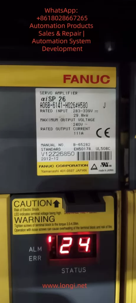
The Fanuc CNC (Computer Numerical Control) system is a core component in modern manufacturing, driving precise machining across industries from aerospace to automotive. These systems, such as the Series 0i-MD, rely on precision servo amplifiers, spindle modules, and control units to ensure high-speed, accurate operation. However, faults such as alarm codes SYS_ALM455 (indicating fan motor stop and system shutdown) and SPM 24 (serial data error) can disrupt production, leading to costly downtime. Based on real-world diagnostics, these alarms often relate to each other, with the failure of a DC bus connector exacerbating the issue.
This article offers a comprehensive technical exploration of these alarms in Fanuc systems, especially focusing on the βiSVSP amplifier series (e.g., model A06B-6164-H343). Based on the Fanuc maintenance manual and troubleshooting guides, we detail the causes, diagnostic methods, repair procedures, and preventive measures. The goal is to provide engineers and technicians with actionable insights to minimize faults and extend system lifespan, following a structured approach from symptom recognition to root cause analysis, ensuring efficient repairs and preventing recurrence.
1. Overview of the Fanuc CNC System
The Fanuc CNC architecture includes key components: the control unit (e.g., Series 0i-MD), servo amplifiers for axis control, spindle amplifiers (SPM) for rotation operations, and power supply modules (PSM). The βiSVSP series integrates the servo and spindle amplifiers into a compact unit, supporting multi-axis operation with high voltage capabilities up to 400V. For example, the A06B-6164-H343 model handles 40/40/80A servo current and 15kW spindle output, with a rated input of 200-240V AC at 50/60Hz.
Critical to the system’s reliability is the cooling mechanism, such as external or internal fans on the amplifier heat sinks, which dissipate heat from power transistors to prevent thermal shutdowns. Serial communication links the CNC controller to amplifiers via optical or electrical cables, ensuring synchronized data transmission of commands and feedback. Failures in these links or power distribution—such as through DC bus connectors (e.g., CX1A/B interface)—can cascade into alarms.
Understanding system interconnects is crucial: the DC bus links share power between modules, so loose connectors may underpower the fan or interrupt serial data, triggering SYS_ALM455 and SPM 24. Alarm logs with program counters (e.g., 10018B30H) and access addresses (e.g., 0100000AH) provide diagnostic clues, with timestamps (e.g., 2026/01/11 19:47:41) used for event correlation.
2. Alarm Code Analysis
SYS_ALM455: Fan Motor Stop and Shutdown
SYS_ALM455 indicates a cooling fan failure, prompting an immediate system shutdown to prevent damage from overheating of the amplifiers or motors. In the Fanuc Series 0i-MD, this alarm appears as “SYS_ALM455 FAN MOTOR STOP AND SHUTDOWN,” typically accompanied by a red LED on the amplifier.
Causes:
Fan Hardware Failure: Motor burnout, bearing seizure, or blockage from accumulated dust. Fans in the βiSVSP units (typically 24V DC, 40mm in size) are prone to wear after 20,000-50,000 hours of operation.
Power Issues: Fan circuit under-voltage due to DC bus fluctuations. Faulty main bus connectors (e.g., loose copper bars or oxidized pins) can drop the voltage below 22.8V DC, causing the fan to stop.
Environmental Factors: High ambient temperatures (>40°C) or poor ventilation increase thermal load, accelerating failure. Electromagnetic interference (EMI) from nearby motors can also disrupt fan control signals.
Software/Parameter Errors: Misconfigured parameters (e.g., No. 7310 for axis sequence) or checksum errors in the servo software, though rare in fan-specific alarms.
Diagnosis:
Visual Inspection: Check the amplifier LED (e.g., red ALM/ERR indicates a fault). Verify fan rotation by powering up the cabinet.
Voltage Measurement: Use a multimeter to measure voltage at the fan terminals; expect a stable 24V DC. Probe the DC bus (nominal 300V) for voltage drops.
Log Analysis: Review CNC diagnostics (Nos. 400-499) for serial status and temperature readings. Use an oscilloscope to check for EMI on cables.
Isolation Test: Disconnect the fan and test it independently. If it doesn’t rotate, the resistance between wires should be infinite.
If the alarm persists after power cycling, suspect an interconnect issue, such as a DC bus fault.
SPM 24: Serial Data Error
SPM 24 indicates a serial communication error between the CNC controller and the spindle amplifier module, shown as “24” on the SPM LED. It indicates data corruption or interruption, typically requiring a power cycle to reset.
Causes:
Communication Interruption: Noise on the serial cable (e.g., optical fibers or CX3/CX38 interface) from EMI, exceeding the maximum cable length (per B-65282EN manual), or poor grounding.
Power-Related Failures: CNC power loss during operation causing under-voltage on the SPM control PCB. Issues with main bus plugs—loose, damaged pins, or arcing—lead to unstable voltage, causing data parity errors.
Hardware Defects: Faulty SPM PCB, transistor modules, or feedback signals. In βiSVSP, this correlates with DC bus undervoltage alarms (e.g., Alarm 5: Low DC Voltage).
Cascading Effect: Often a secondary consequence of SYS_ALM455. The shutdown triggered by the fan failure disrupts power, resulting in SPM 24 as a “normal” response, but a persistent issue signals deeper problems.
Diagnosis logs may show “Serial Transfer Data Error,” with DGN No. 471 detailing spindle speed ratios or feedback mismatches.
Diagnosis:
Cable Inspection: Check for damage on the serial link. Test continuity and shielding. Use a logic analyzer to measure signal integrity.
Power Verification: Confirm AC input (200-240V) and DC bus (300V). Voltage fluctuations point to bus connector issues.
Parameter Review: Check Nos. 400-499 for communication status. Reset if noise is suspected.
LED Interpretation: SPM shows “-24” or “0 24” indicating specific sub-errors (e.g., cable fault vs. PCB issue).
3. Interlinking Alarms and DC Bus Issues
SYS_ALM455 and SPM 24 often occur together because they share a dependence on the DC bus. The main bus connector (copper bars or CX1 interface) distributes power; failures here lead to a cascade of alarms:
Voltage drops cause fan stoppage (SYS_ALM455).
Instability damages serial data (SPM 24).
In diagnostics, a loose connector manifests as intermittent alarms, exacerbated by vibration.
4. Fault Diagnosis Methodology
Effective diagnosis follows a logical, layered approach: symptom recording, isolation, and verification.
1. Initial Assessment:
Record alarm timestamps, program counters, and access data on the CNC screen.
Check the amplifier LED: red ALM indicates an error, blank display indicates a power failure.
Use Fanuc’s teaching pendant or MDI panel to access parameters.
2. Tools and Techniques:
Multimeter/Oscilloscope: For voltage, resistance, and waveform analysis.
Thermal Imaging: Detect hotspots on amplifiers or connectors.
Diagnostic Software: Fanuc’s PMC ladder logic viewer for signal tracking.
Isolation: Swap modules (e.g., test the fan on a separate power supply) to pinpoint the fault.
3. Step-by-Step Protocol:
Power Cycle: Reset alarms; if persistent, continue.
Component Testing: Fan (rotation test), cables (continuity), connectors (visual/torque checks).
Advanced: Monitor DGN parameters during operation to detect transient errors.
For βiSVSP, refer to the wiring diagram in B-65322. Document findings to identify patterns.
5. Repair Procedures
Repairs must prioritize safety: isolate power, use ESD protection, and follow OEM specifications.
For SYS_ALM455:
Fan Replacement: Locate fan on the amplifier heat sink (rear/top). Disconnect, remove (screws/clips), and install a new fan (e.g., A06B-6134-K002). Test rotation.
Cleaning: Use compressed air on the heat sink; avoid solvents on electronics.
Power Repair: If voltage is low, reset the DC bus plug; clean oxidation with isopropyl alcohol. Torque to specification (e.g., 2-3 Nm).
Verification: Power on, monitor for 30 minutes, and check diagnostics to clear.
For SPM 24:
Cable Repair: Replace faulty serial cables; ensure proper shielding/grounding.
PCB Replacement: If the PCB is suspected, replace the SPM control board (A20B-1009-0650 series).
Bus Connector Repair: Discharge the system, remove the plug, and check the pins. Clean/replace if damaged; reconnect securely.
Reset Sequence: Power down CNC and amplifier. Wait 5 minutes. Power on the amplifier first, then CNC.
Integrated Fix for Linked Alarms:
Address the root cause (e.g., bus plug): disconnect, test resistance (<1Ω), and reassemble.
After repairs: run spindle test (M03 S1000) and axis jog; monitor temperatures.
If the alarm recurs, escalate to Fanuc Service for PCB analysis.
Total repair time: 1-4 hours, depending on access.
6. Preventive Maintenance Best Practices
Proactive maintenance can reduce alarm frequency by 70-80%, based on industry benchmarks.
Daily/Weekly Routine:
Visual Inspection: Check fans, cables, and connectors for wear.
Cleaning: Remove dust from the cabinet; use intake filters.
Monitoring: Check CNC logs for temperature (e.g., spindle load table).
Monthly/Quarterly:
Voltage Audit: Measure input/output; calibrate if deviation >5%.
Fan Service: Lubricate bearings; replace every 2 years.
Cable Integrity: Torque check for bus plugs; validate EMI shielding.
Annual Overhaul:
Comprehensive Diagnostics: Use Fanuc tools for parameter backup, firmware updates.
Component Replacement: Batteries, fuses (e.g., F3 in PSM).
Training: Ensure operators follow the power-up sequence (amplifier before CNC).
Checklists: Daily (cleaning), 500 hours (check), 2000 hours (overhaul). Fanuc’s lifetime support and refurbished parts programs help control costs. Grounding to Class C standards prevents noise-induced errors.
7. Case Study: Resolving Interlinking Alarms in a Production Environment
In a recent scenario involving Fanuc Series 0i-MD and βiSVSP amplifiers, SYS_ALM455 and SPM 24 appeared simultaneously on 2026/01/11 at 19:47:41. Initial checks showed no fan rotation, with the DC bus voltage at 250V (below the nominal 300V). Diagnostics traced the fault to a loose main bus plug, causing undervoltage.
Fix: The system was powered off, and after cleaning, the plug was reset. The fan was independently tested (rotating at 24V). After repairs, alarms cleared, and spindle tests confirmed stable operation. Prevention: Added monthly torque checks and EMI filters. Downtime: 2 hours; prevented recurrence through planned maintenance.
This case highlights the value of comprehensive diagnostics, consistent with Fanuc’s B-65285EN manual recommendations.
Conclusion
SYS_ALM455 and SPM 24 showcase how interconnected Fanuc CNC components can lead to cascading faults, often stemming from power distribution issues like DC bus connectors. By mastering diagnostics (logs, tools), repairs (step-by-step), and prevention (routines), technicians can achieve >99% uptime. Always consult Fanuc manuals (e.g., B-65322, B-65282EN) and leverage OEM support for complex issues. Implementing these strategies not only resolves immediate problems but fosters long-term system resilience and optimized manufacturing efficiency.
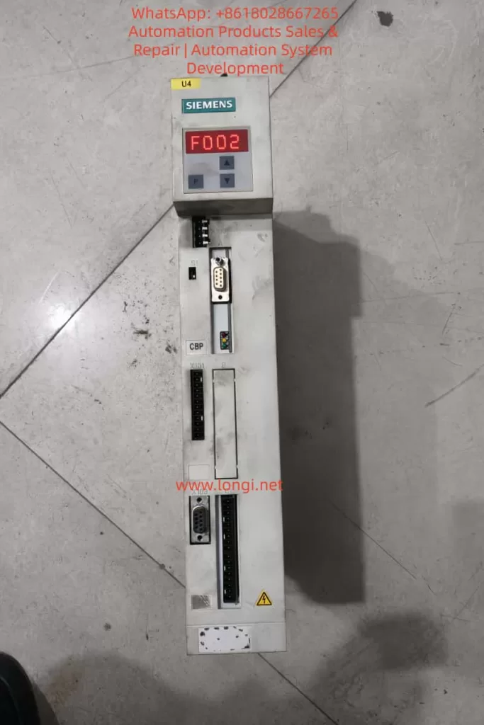
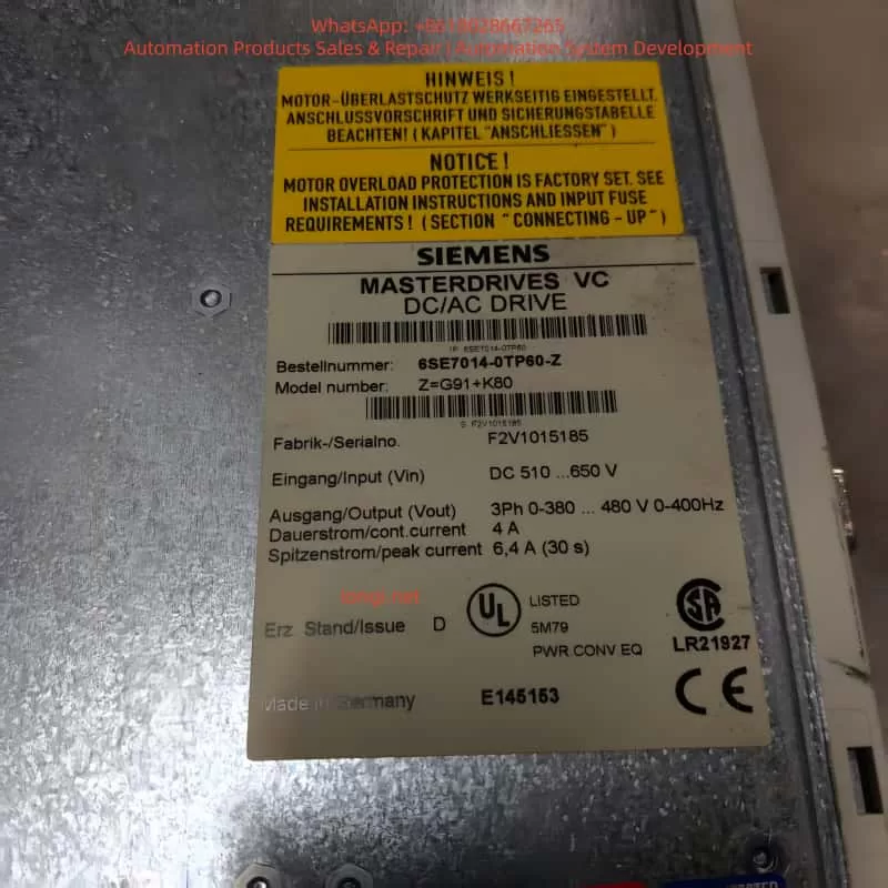
The Siemens Masterdrives VC series is a high-performance vector-controlled drive system widely used in industrial automation, traction systems, and hoisting equipment. Fault code F002 indicates a precharging fault, meaning that the DC link voltage fails to reach the required threshold within the specified time (typically 3 seconds). This fault usually occurs when the DC bus voltage does not reach approximately 80% of (P071 × 1.34).
The F002 fault is commonly related to power supply issues, faulty contactors, damaged precharge circuits, or incorrect parameter configuration. It prevents the drive from completing the startup sequence, causing system downtime and potential production losses.
This article provides a comprehensive technical guide covering the working principle, fault mechanism, diagnostic methods, corrective actions, real-world case studies, and preventive maintenance strategies. The content is based on Siemens documentation and field experience, and is intended to help engineers quickly locate root causes and restore reliable operation.
1. Introduction
In modern industrial environments, variable frequency drives such as the Siemens Masterdrives VC series are core components for precision motor control. These drives support multiple control modes ranging from open-loop V/Hz to closed-loop vector control, enabling accurate speed and torque regulation for asynchronous and synchronous motors.
The F002 precharging fault is one of the most frequently encountered startup faults. It occurs when the DC link voltage does not build up correctly during power-on. This fault not only prevents the drive from starting, but can also indicate deeper electrical or hardware issues, such as unstable incoming power, defective precharge resistors, or main contactor malfunctions.
Industrial statistics show that DC link and precharge-related faults account for approximately 15–20% of inverter startup failures, making systematic troubleshooting essential for minimizing downtime.
2. Overview of Siemens Masterdrives VC Series
The Siemens Masterdrives VC (Vector Control) series is a modular drive platform designed for applications requiring high dynamic response and accurate torque control.
Typical features include:
Input voltage: 3-phase 380–480 V AC, 50/60 Hz
Output: 3-phase 0–480 V, 0–500 Hz
Power range: From less than 1 kW up to several hundred kW
DC link voltage: Approximately 1.34 × line voltage
Control modes:
V/Hz open loop (fans, pumps)
Vector control closed loop (hoists, traction, extruders)
Integrated protection functions include overload monitoring, temperature estimation, ground fault detection, and extensive fault logging.
The Masterdrives VC series is widely used in cranes, rolling mills, traction systems, conveyors, and test benches where precise dynamic performance is required.
3. Drive Operating Principle
Masterdrives VC uses vector control technology to decouple magnetic flux and torque. The operating sequence includes:
Rectification and Precharging
Incoming AC voltage is rectified into DC. The precharge circuit limits inrush current while charging the DC link capacitors.
DC Link Stabilization
The DC capacitors store energy and smooth voltage ripple. During precharging, the DC voltage must rise above the internal monitoring threshold.
Inversion
IGBT modules generate a PWM output to supply the motor with variable voltage and frequency.
Control Loop
Encoder or analog feedback enables closed-loop speed or torque control.
State Machine
The internal sequence transitions from:
Ready to power-up
Precharging
Ready
Run
If the DC voltage does not rise fast enough during precharge, the system remains in the precharging state and finally triggers F002.
4. Parameterization and Startup Process
Commissioning is typically performed using the PMU panel, OP1S, or DriveMonitor software.
Important configuration steps include:
Factory reset: P052 = 2
Enter MLFB number: P070
Motor data: P100 – P109
Automatic motor identification: P052 = 7 or 8
Control tuning: P225 – P229, P253 – P254
Feedback configuration: P208, P209
Setpoint source: P443
Contactor control:
Output: P612
Feedback: P591
Auto restart: P366, P367
During precharge, parameter P071 (supply voltage) determines the DC voltage reference. Parameter r006 displays actual DC link voltage.
5. Fault Code System
Masterdrives VC uses three-digit fault codes.
Fxxx: Trip faults (pulse inhibited)
Axxx: Alarms (drive still running)
Fault memory registers:
r947 – fault code
r949 – fault value
r951 – timestamp
F002 belongs to the precharging fault group and is directly linked to the startup state machine.
6. Detailed Explanation of F002 Precharging Fault
Fault definition: The DC link voltage fails to reach the defined threshold within the monitoring time.
Threshold: Approximately 80% of (P071 × 1.34)
Typical example: P071 = 400 V → DC nominal ≈ 536 V → Threshold ≈ 430 V
Fault condition: If r006 < threshold after approximately 3 seconds during the precharge phase, F002 is triggered.
Typical root causes:
Incorrect or unstable incoming power
Main contactor not closing
Missing contactor feedback
Failed precharge resistor or board
DC capacitors degraded
Wrong hardware configuration
Long-term storage without capacitor reforming
7. Diagnostic Procedure
A structured approach is recommended:
Check incoming power
Measure 3-phase voltage
Verify P071 matches actual supply
Monitor DC link voltage
Observe r006 during startup
Verify contactor operation
Check P612 output
Check P591 feedback signal
Measure coil voltage
Observe drive states
r001 = 010 indicates precharging
Inspect hardware
Precharge resistors
DC bus capacitors
Wiring and fuses
Check grounding
Run P354 ground fault test
Analyze fault memory
r947 – r951
Perform internal test
P052 = 11
8. Corrective Actions
Depending on findings:
Adjust P071 or correct power supply
Repair or replace contactor and feedback wiring
Replace precharge board or resistors
Reform or replace DC capacitors
Reinitialize parameters
Replace defective control or power modules
After repair, clear fault and restart. Monitor DC voltage rise and confirm the drive transitions to “Ready” state.
9. Case Studies
Case 1 – Traction drive in steel plant
F002 occurred intermittently. DC voltage only reached 520 V. Precharge resistor found open-circuit. Replaced precharge board and stabilized power supply. System restored.
Case 2 – Crane slewing system
Main fuse failure damaged precharge resistor. F002 occurred every startup. Replaced resistor and fuse. Verified contactor feedback.
Case 3 – Long-term stored drive
DC capacitors lost forming. Reformed capacitors slowly using external DC supply. Fault cleared.
10. Preventive Maintenance and Best Practices
Annual inspection of DC link voltage and contactors
Capacitor reforming after long storage
Regular parameter backup
Maintain proper cabinet temperature and humidity
Use shielded motor cables
Update firmware where applicable
Operator training on startup diagnostics
11. Advanced Configuration Considerations
Key parameters related to F002:
Parameter
Description
Typical Value
Relevance
P071
Line voltage
380–480 V
Defines DC threshold
P366
Auto restart
0–3
Monitoring behavior
P367
Restart delay
0–650 s
Precharge timing
P612
Contactor output
1001
Enables precharge
P591
Contactor feedback
1003
Confirms closure
r006
DC voltage
> threshold
Real-time check
r001
Drive state
010 = precharge
Fault location
DriveMonitor software is strongly recommended for trend analysis and documentation.
12. Conclusion
The Siemens Masterdrives VC F002 precharging fault is a critical startup protection mechanism. Although common, it can be resolved efficiently through systematic diagnosis focusing on supply voltage, precharge circuitry, and contactor control.
With proper maintenance and configuration, Masterdrives VC systems remain highly reliable. Applying the methods described in this guide can significantly reduce downtime and extend equipment service life.
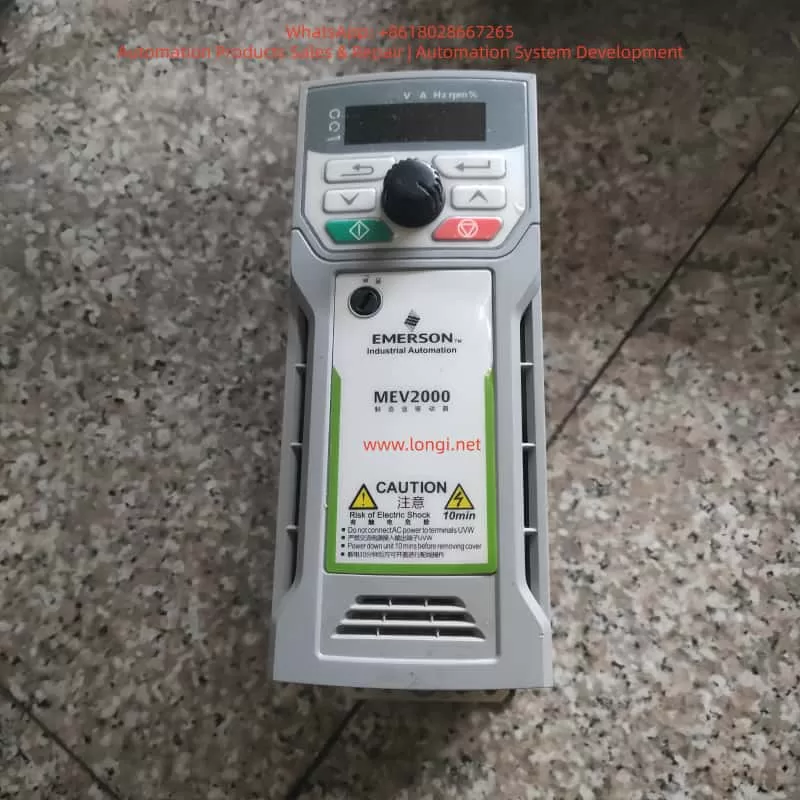
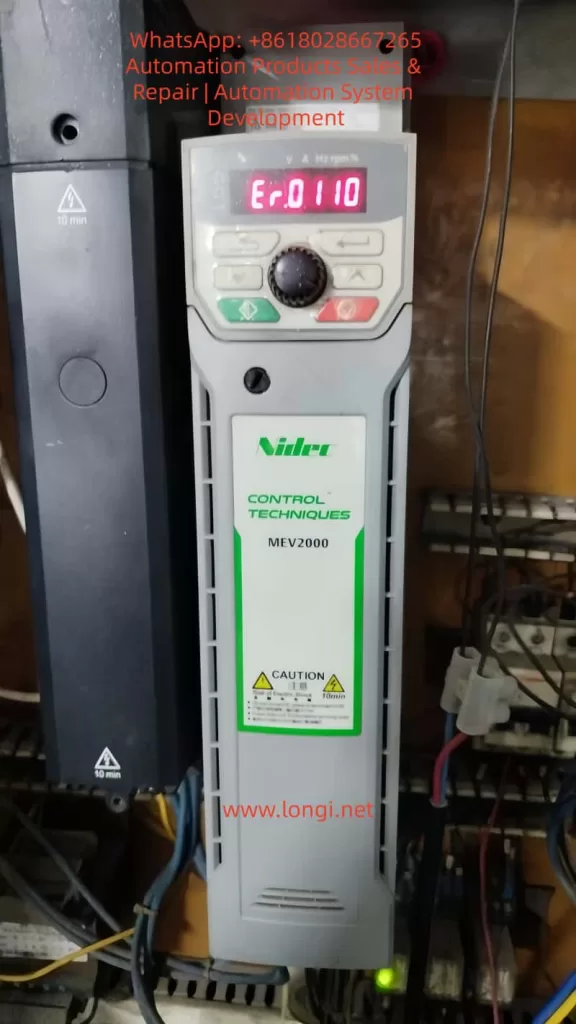
The MEV2000 series inverter is a high-performance industrial drive developed by Nidec Control Techniques (formerly Emerson). It is widely applied in fan, pump, conveyor, and textile machinery systems. While the MEV2000 series is known for its robust design and advanced vector control capability, hardware-level faults can still occur under harsh operating conditions. Among these, fault code Er.0110 is a critical alarm typically associated with large-frame models and indicates internal hardware abnormalities.
This article provides a systematic technical analysis of the MEV2000 inverter, its working principles, installation standards, parameter configuration, common fault types, and focuses in depth on the diagnosis and maintenance strategy for Er.0110 hardware faults.
1. Overview of the MEV2000 Series Inverter
The MEV2000 series inverter is designed for industrial motor control applications, supporting both induction motors and permanent magnet synchronous motors. It integrates vector control and V/F control technologies to meet various load requirements.
Key specifications include:
Power range: 0.37 kW to 250 kW
Voltage classes: 200 V, 400 V, 575 V
Control modes: V/F, open-loop vector, closed-loop vector
Built-in EMC filter, RS485 communication interface, and PID controller
For example, the MEV2000-400-0011 model delivers a continuous output current of 1.1 A and up to 1.65 A in heavy-duty mode. The product complies with IEC 61800-3 EMC standards and has an IP20 protection rating, upgradeable to IP66 using enclosure options.
The drive integrates overload protection, short-circuit monitoring, and thermal modeling, making it suitable for pumps, fans, conveyors, and textile machinery.
2. Operating Principle and Control Technology
The inverter converts fixed-frequency AC power into variable-frequency, variable-voltage output using PWM (Pulse Width Modulation) technology. Internally, the MEV2000 consists of a rectifier, DC bus, capacitor bank, inverter bridge, and control board.
AC input is rectified to DC.
DC bus capacitors stabilize the voltage (typically ~565 V for 400 V models).
The inverter uses Space Vector Modulation (SVM) to improve harmonic performance and energy efficiency. Under vector control, torque and flux are independently regulated using Park transformation algorithms. Rotor position is obtained via encoder feedback or sensorless estimation.
In V/F mode, voltage-frequency ratio is maintained constant, with low-frequency voltage compensation to prevent torque loss. Built-in PID functions allow closed-loop control for pressure, flow, and tension systems. Communication is based on Modbus RTU, supporting baud rates up to 38.4 kbps for PLC and SCADA integration.
3. Installation and Wiring Standards
Recommended installation environment:
Temperature: –10 °C to 50 °C
Humidity: <95% RH, non-condensing
Free from corrosive gas, oil mist, and vibration
Wall-mounted installation requires at least 100 mm top clearance and 150 mm bottom clearance. For panel installation, forced ventilation is recommended.
Shielded motor cables shorter than 50 m are recommended. Control terminals include digital inputs (DI1–DI5), analog inputs (AI1/AI2), and relay outputs (RO1/RO2). RS485 uses differential A/B terminals with 120 Ω termination.
Before first power-on, verify insulation resistance >5 MΩ. Factory reset can be performed using parameter F0.00 = 1.
4. Parameter Configuration and Optimization
Key parameter groups:
F0 group: Control mode (F0.02 = 0 for V/F)
FH group: Motor nameplate data
F4 group: Auto-tuning (static or rotating)
F2 group: Acceleration and braking control
F5 group: PID configuration
F7 group: Digital input assignment
FF group: Communication parameters
Auto-tuning calculates stator resistance, leakage inductance, and magnetizing inductance to optimize torque response. Proper configuration significantly improves stability and fault immunity.
5. Common Fault Types and Diagnostic Approach
MEV2000 fault codes begin with “Er.” and are classified into overload, overvoltage, undervoltage, communication faults, and hardware faults.
Examples:
Er.0010: Overcurrent
Er.0020: DC bus overvoltage
Er.0030: Undervoltage
Er.0180: Communication fault
Er.0110: Hardware fault (large-frame models)
Fault history can be accessed via Fn.00. Diagnosis should combine fault code review,现场 measurement, waveform observation, and power quality evaluation.
6. Detailed Analysis of Er.0110 Fault
Er.0110 (sub-code 1) indicates that internal operating parameters have exceeded safe limits and is limited to high-power MEV2000 models (typically above 75 kW). It is categorized as a hardware-related alarm.
Typical causes include:
IGBT module failure or gate driver abnormality
DC bus capacitor aging or imbalance
EEPROM or control board malfunction
Unstable or unbalanced input power supply
Grounding defects and EMI interference
Diagnostic steps:
Record operating conditions before trip
Power off and discharge for 10 minutes
Check DC bus connections and insulation resistance
Reset and observe recurrence
Measure DC bus ripple (<50 V p-p recommended)
Inspect power modules and capacitor bank
Corrective measures:
Replace faulty IGBT modules
Renew aging electrolytic capacitors
Upgrade firmware
Install input reactors or harmonic filters
Improve grounding and cabinet ventilation
Field experience shows that more than 70% of Er.0110 events are linked to external power quality problems rather than internal device defects.
7. Maintenance Strategy and Case Studies
Maintenance includes both preventive and corrective actions.
Preventive measures:
Monthly cleaning of cooling fans and heat sinks
Quarterly insulation and grounding inspection
Annual auto-tuning and firmware updates
Corrective maintenance tools include multimeters, oscilloscopes, thermal cameras, and insulation testers.
Typical cases:
Textile plant: Er.0110 caused by phase imbalance
Pump station: capacitor degradation
Conveyor system: moisture ingress on control board
Establishing spare part inventory and predictive monitoring through Modbus data collection significantly reduces downtime.
8. Maintenance and Upgrade Recommendations
Replace cooling fans periodically
Back up parameters using SD card modules
Maintain cabinet temperature below 40 °C
Implement LOTO safety procedures
Consider upgrading to newer Unidrive M200 series platforms for Ethernet and advanced diagnostics
Regular maintenance can extend service life beyond ten years and reduce unexpected shutdowns.
9. Conclusion
The MEV2000 inverter remains a reliable industrial platform, but hardware faults such as Er.0110 require systematic diagnosis and professional maintenance. By understanding internal principles, ensuring proper installation, and implementing preventive maintenance, users can significantly improve system stability and service continuity.
The HACH SC1000 Water Quality Analyzer Controller is a high-precision, multi-parameter monitoring platform widely used in drinking water treatment, industrial wastewater treatment, and environmental monitoring applications. Designed as a modular and scalable controller, the SC1000 supports multiple digital sensors and communication options, enabling centralized monitoring and control of complex water quality systems.
This user guide provides a comprehensive overview of the SC1000 controller, including product features, installation procedures, operating instructions, and maintenance guidelines, to help users deploy and operate the system efficiently and reliably.
1. Product Overview
1.1 Key Features
The SC1000 is a menu-driven, modular multi-parameter controller with the following core advantages:
Multi-parameter monitoring: Supports simultaneous connection of multiple digital sensors such as pH, dissolved oxygen, conductivity, turbidity, chlorine, and more.
High-accuracy measurement: Advanced digital signal processing ensures stable, precise, and repeatable measurements.
Modular expansion: Supports plug-in communication cards, analog/digital I/O cards, and relay modules.
User-friendly interface: Color display with intuitive menu navigation and on-screen configuration.
Remote monitoring capability: Supports Ethernet and fieldbus modules for remote data access and system integration.
1.2 System Components
A standard SC1000 system typically consists of:
Display module: Color display unit for real-time values, alarm status, and system configuration.
Probe (controller) module: Core processing unit for sensor communication, data acquisition, and output control.
Expansion cards: Including relay cards, analog input/output cards, and digital or fieldbus communication modules.
Power and accessories: Power cables, fuses, mounting brackets, terminal blocks, and communication cables.
2. Installation Guide
2.1 Pre-installation Checklist
Before installation, verify the following:
All components are complete and undamaged.
The installation environment is dry, well ventilated, and free of strong electromagnetic interference.
Adequate space is reserved for cable routing, ventilation, and maintenance access.
Probe module: approximately 315 × 255 × 120 mm (excluding display)
Clearance requirements:
At least 5 cm clearance on sides and top for heat dissipation
At least 15 cm clearance at the bottom for wiring
2.2.2 Wall-mount Installation
Mark mounting hole positions on the wall according to the backplate.
Drill holes and insert expansion anchors.
Hang the controller on the mounting screws.
Secure the bottom screws and verify the unit is firmly fixed.
2.2.3 Pipe or Panel Mounting
Use the official HACH mounting kit.
Install the brackets securely on horizontal or vertical pipes.
Ensure vibration is minimized and cables are properly strain-relieved.
2.3 Electrical Installation
2.3.1 Power Supply Connection
The SC1000 supports both AC and DC power input:
AC power: 100–240 VAC, 50/60 Hz
DC power: 24 VDC (18–30 VDC range)
Installation procedure:
Disconnect all power sources before wiring.
Remove the probe module cover and safety barrier.
Route the power cable through the sealed cable gland.
Connect the power wires to the designated terminals.
Reinstall the safety barrier and enclosure cover.
2.3.2 Expansion Card Wiring
Relay modules
Disconnect power before installation.
Remove the relay cover.
Wire alarm or control loads according to the terminal diagram.
Verify correct NO/NC selection and tighten all screws.
Analog / digital I/O cards
Connect signal cables according to the card type (4–20 mA, digital input, digital output).
Use shielded cables where possible.
Ground shields at one end only to avoid ground loops.
2.4 Network and Sensor Connection
The SC1000 uses a digital network bus to connect probe modules and sensors.
Installation steps:
Strip and prepare the network cable.
Connect the wires to the communication terminal block.
Secure the connector and install termination resistors if required.
Insert the connector into the probe module network port.
Power on the system and verify sensor recognition.
3. Operating Instructions
3.1 Display and Interface Operation
3.1.1 Touchscreen Calibration
Touchscreen calibration is recommended during initial commissioning or after display replacement.
Procedure:
Enter System Settings → Display Settings → Touchscreen Calibration
Follow on-screen instructions and confirm calibration points.
3.1.2 Menu Navigation
The main menu provides access to:
Sensor status
Measurement values
Configuration and calibration
Outputs and alarms
System diagnostics
Navigation is performed using on-screen icons and soft keys.
3.2 Sensor Management
3.2.1 Sensor Status Monitoring
View real-time measurements for each connected sensor.
Check diagnostic messages, warnings, and error codes.
Confirm communication and sensor health status.
3.2.2 Sensor Configuration
Within the sensor menu, users can configure:
Measurement units
Calibration parameters
Alarm thresholds
Output assignments
Temperature compensation and filtering
Always follow sensor-specific manuals when performing calibration.
3.3 System Configuration
3.3.1 Output Settings
Configure analog outputs (for example, 4–20 mA)
Assign outputs to specific parameters
Define scaling ranges, damping time, and failure behavior
3.3.2 Relay Settings
Assign relays to alarms, setpoints, or system events
Configure activation logic, delays, and hysteresis
Test relay actions before commissioning
3.3.3 Communication and Network Settings
Set Modbus address and baud rate
Configure Ethernet or fieldbus parameters
Verify data format consistency with PLC or SCADA systems
4. Maintenance and Troubleshooting
4.1 Routine Maintenance
Inspect enclosures for dust, corrosion, or moisture ingress.
Verify all terminals and connectors are secure.
Clean the display and housing with a soft, damp cloth.
Perform periodic sensor calibration according to application requirements.
4.2 Fuse Replacement
Before replacing fuses, disconnect all power sources.
Typical fuse types include slow-blow fuses such as M3.5A or T8A (refer to the nameplate).
Procedure:
Remove the probe module cover.
Take out the damaged fuse.
Insert a fuse with identical rating.
Reinstall covers and restore power.
4.3 Common Faults and Solutions
No display or no power
Check power supply voltage.
Inspect fuses and terminal connections.
Unstable or abnormal readings
Check sensor wiring and connectors.
Perform recalibration.
Inspect sensors for fouling or damage.
Communication errors
Verify address, baud rate, and protocol settings.
Inspect network cables and termination.
Check expansion cards and power stability.
5. Conclusion
The HACH SC1000 controller is a powerful and flexible water quality monitoring platform suitable for both industrial and municipal applications. With proper installation, configuration, and maintenance, the SC1000 provides reliable long-term performance and accurate multi-parameter measurement.
By following the procedures and best practices described in this guide, users can ensure stable system operation, accurate data acquisition, and efficient troubleshooting.