
1. Overview of the Fault Phenomenon
The Particle Metrix ZetaView is a nanoparticle tracking analysis (NTA) instrument widely used for the characterization of exosomes, viruses, liposomes, nanomaterials, protein aggregates, colloidal suspensions, and other nanoscale particles. Although it appears externally as a compact benchtop laboratory analyzer, internally it integrates a laser illumination system, microscopic imaging system, sample cell positioning mechanism, temperature and fluid control system, camera acquisition module, motion control system, and dedicated analysis software.
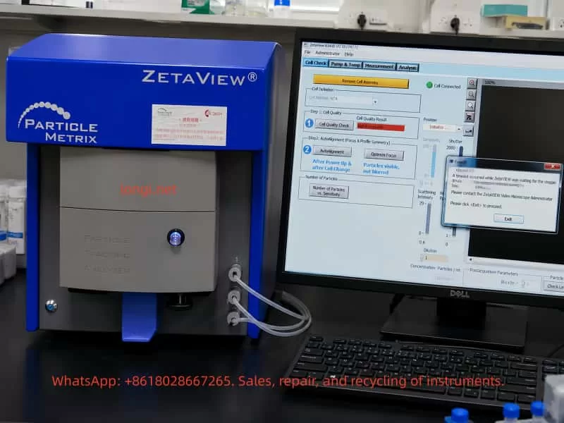
One common field failure encountered on this type of instrument is startup initialization failure. After powering on the instrument and launching the ZetaVIEW software, the system cannot complete the self-check procedure. During initialization or Cell Check, the software displays an error message similar to:
A timeout occurred while ZetaVIEW was waiting for the stepper drives to stop.
ZetaVIEW will be stopped without saving the configuration file.
Please contact the ZetaVIEW Video Microscope Administrator.
This error does not simply indicate a software crash or Windows problem. It means that during startup initialization, the software issued a motion command to the internal stepper motor system, but the instrument failed to return the expected “motion completed” or “drive stopped” status within the allowed time window.
For service engineers, this is a critical distinction. Reinstalling the software or replacing the PC may not resolve the issue. In most cases, the fault is associated with one or more of the following subsystems:
- Sample cell installation or positioning problems
- Mechanical blockage inside the motion platform
- Stepper motor or stepper driver failure
- Home sensor or limit switch malfunction
- Motion controller communication errors
- Internal power supply instability
- Liquid contamination, salt crystallization, or corrosion inside the instrument
Therefore, when a ZetaView analyzer reports a “stepper drives timeout” error during startup, troubleshooting should focus primarily on the internal motion control system rather than the software alone.
2. Basic Internal Structure of the ZetaView NTA Analyzer
Understanding the internal architecture of the analyzer is essential for correct fault diagnosis.
The ZetaView is not merely an optical microscope. Its operation is based on nanoparticle tracking analysis. Nanoparticles suspended in liquid undergo Brownian motion. A laser illuminates the particles inside the sample cell, and the microscopic imaging system captures the scattered light from each particle. The software then calculates particle size distribution by analyzing particle motion trajectories.
To achieve this, the instrument includes several interconnected systems.
2.1 Laser Illumination System
The analyzer requires a stable laser source to illuminate nanoparticles inside the measurement cell. Scattered light from the particles is captured by the camera system.
Laser-related failures usually produce symptoms such as:
- Dark image
- No visible particles
- Weak scattering intensity
- High optical noise
- Unstable illumination
However, laser faults generally do not directly trigger “stepper drive timeout” errors unless multiple initialization procedures fail simultaneously.
2.2 Microscopic Imaging System
The instrument includes:
- Microscope optics
- Imaging camera
- Focus adjustment mechanism
- Optical positioning assembly
The software functions “Auto Alignment” and “Optimize Focus” indicate that the system must move and adjust optical components during initialization.
If the imaging system fails, typical symptoms include:
- Black image
- Blurred particles
- Unstable focus
- Excessive background noise
- Missing particle trajectories
Again, these faults alone normally do not generate the specific “waiting for the stepper drives to stop” error unless the motion system involved in focusing is malfunctioning.
2.3 Sample Cell and Fluidic System
The sample cell is where nanoparticle measurements occur. Tubing connections allow sample injection, flushing, and fluid exchange.
The software screen often displays messages such as:
- Remove Cell Assembly
- Cell Connected
- Cell Quality Check
If the sample cell is improperly installed, contaminated, misaligned, or mechanically interfering with the positioning mechanism, the motion platform may fail during initialization.
Common issues include:
- Misaligned sample cell
- Salt residue inside the holder
- Damaged sealing ring
- Deformed mounting mechanism
- Mechanical obstruction
- Improper insertion depth
2.4 Motion Control System
The motion system is the most important subsystem related to this fault.
Inside the analyzer, several precision movements may be controlled by stepper motors:
- Sample cell positioning
- Focus adjustment
- Optical path alignment
- Stage positioning
- Internal calibration movement
During startup, the software typically performs:
- Homing operations
- Position calibration
- Focus initialization
- Alignment verification
- Motion completion checks
If any axis fails to stop correctly, or if the controller does not receive the expected completion signal, the software eventually reports a timeout error.
3. Technical Meaning of the Error Message
The key phrase is:
waiting for the stepper drives to stop
This is extremely important.
It means the software successfully communicated with the instrument and attempted to control the internal motion system. The failure occurred after motion commands were already issued.
This implies several important conclusions:
- The instrument is at least partially communicating with the PC.
- The motion initialization process has started.
- The software is waiting for confirmation that the stepper-driven mechanism has stopped or reached its target position.
- That confirmation never arrived within the allowed time.
Therefore, the root problem lies somewhere within the motion control chain:
- Mechanical movement
- Stepper motors
- Driver electronics
- Home sensors
- Limit switches
- Motion feedback logic
- Controller communication
This is not primarily a Windows or GUI software problem.
4. Common Causes of the Fault
4.1 Sample Cell Assembly Problems
The appearance of “Remove Cell Assembly” suggests that the software is checking sample cell status during startup.
If the sample cell is:
- Improperly seated
- Mechanically obstructing movement
- Contaminated
- Deformed
- Incorrectly installed
the initialization sequence may fail.
This is particularly common when:
- Operators force the cell into position
- Salt crystals accumulate
- Sample liquid leaks into the holder
- The positioning mechanism becomes misaligned
A practical first step is always:
- Power off the instrument
- Remove the sample cell
- Clean the mounting area
- Restart the analyzer
- Retry initialization
If the instrument passes startup without the cell installed, the fault is strongly related to the sample cell assembly or associated positioning mechanism.
4.2 Mechanical Blockage
Mechanical resistance is one of the most common causes of stepper timeout errors.
Typical sources include:
- Dried sample residue
- Salt crystallization
- Corrosion
- Contaminated guide rails
- Damaged bearings
- Misaligned sliders
- Bent lead screws
- Foreign debris inside the motion path
Typical symptoms:
- Humming motor without movement
- Clicking or knocking sounds
- Intermittent startup success
- Axis stalling during homing
- Excessive resistance during manual movement
NTA analyzers often operate with biological buffers and saline solutions. Even small liquid leaks can eventually contaminate precision mechanical assemblies.
4.3 Stepper Motor Failure
Stepper motors themselves can fail, although this is less common than mechanical blockage or driver board faults.
Possible motor-related issues include:
- Open motor winding
- Shorted winding
- Connector failure
- Bearing seizure
- Motor overheating
- Insufficient holding torque
- Damaged cables
Diagnostic methods include:
- Measuring winding resistance
- Checking motor holding torque
- Observing motor vibration
- Listening for abnormal noise
A motor that vibrates but does not rotate often indicates either:
- Mechanical blockage
- Incorrect drive signals
- Coil phase problems
- Driver current failure
4.4 Stepper Driver Board Failure
The stepper driver board converts motion commands into motor current.
Failures may involve:
- Burned driver ICs
- Overcurrent protection triggering
- Damaged MOSFETs
- Corroded PCB traces
- Loose connectors
- Missing enable signals
- Driver overheating
- Power supply collapse
Typical symptoms:
- Motor has no holding torque
- Motor briefly moves then stops
- Driver IC overheating
- Repeated startup failures
- Axis movement instability
Because many ZetaView instruments use proprietary motion control boards, board-level diagnosis may require oscilloscope testing and electronic repair skills.
4.5 Home Sensor or Limit Switch Failure
During startup, the instrument typically performs homing operations.
The motion axis moves toward a reference position until:
- A home sensor activates
- A limit switch changes state
- A position feedback signal is detected
If this feedback never occurs, the software waits indefinitely until timeout.
Common causes include:
- Dust blocking optical sensors
- Broken limit switches
- Misaligned sensor flags
- Loose sensor connectors
- Broken wires
- Failed Hall sensors
- Corroded optical interrupters
This is one of the most common root causes of startup timeout faults.
4.6 Internal Power Supply Problems
Motion systems require stable power.
Typical internal voltages include:
- 24V motor supply
- 12V auxiliary supply
- 5V logic supply
Power-related faults may produce:
- Random startup failures
- Weak motor movement
- Driver resets
- Unstable communication
- Excessive ripple noise
- Voltage drop during motion
Important diagnostic points include:
- Voltage stability under load
- Ripple measurement
- Capacitor aging
- Connector oxidation
- Power supply overheating
A static voltage reading alone is insufficient. Dynamic measurements during motor movement are far more useful.
4.7 Communication or Software Configuration Issues
Although the primary fault is usually hardware-related, communication problems should still be considered.
Potential issues include:
- USB communication instability
- Driver mismatch
- Incorrect software version
- Permission conflicts
- Corrupted configuration files
- PC power management problems
However, if the software already reaches the Cell Check interface and displays “Cell Connected,” communication is likely at least partially functional.
Therefore, communication issues are usually secondary rather than primary causes.
5. Recommended Troubleshooting Procedure
Step 1 – Record the Complete Failure Behavior
Before disassembly, record:
- Software version
- Exact error message
- Startup timing
- Motor sounds
- Recent maintenance history
- Sample leakage history
- Transport history
- Environmental conditions
This information greatly improves diagnostic efficiency.
Step 2 – Perform Minimal Startup Configuration
Reduce the system to the simplest possible state:
- Remove the sample cell
- Disconnect unnecessary peripherals
- Restart the analyzer
- Observe initialization behavior
If startup succeeds without the sample cell installed, focus on the cell assembly mechanism.
Step 3 – Listen to Internal Motion Behavior
Motor sounds provide valuable clues.
No sound at all
Possible causes:
- No power
- Dead driver board
- Controller not issuing commands
Humming without movement
Possible causes:
- Mechanical blockage
- Insufficient drive current
- Jammed axis
Repetitive clicking
Possible causes:
- Failed homing
- Sensor malfunction
- Axis hitting mechanical stop
Brief movement then timeout
Possible causes:
- Feedback failure
- Motion interruption
- Controller communication issue
Step 4 – Inspect Mechanical Assemblies
Check for:
- Corrosion
- Salt deposits
- Contamination
- Misalignment
- Loose couplings
- Damaged rails
- Broken belts
- Liquid intrusion
Mechanical inspection should always be performed carefully to avoid disturbing optical alignment.
Step 5 – Check Home Sensors and Limit Switches
Measure:
- Sensor supply voltage
- Output signal switching
- Connector integrity
- Wiring continuity
A failed home sensor can completely prevent successful initialization even if the motor itself is functioning normally.
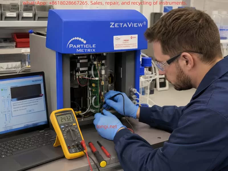
Step 6 – Test Motors and Driver Boards
Key checks include:
- Winding resistance
- Driver board supply voltage
- Enable signals
- STEP/DIR signal activity
- Motor holding torque
- Driver temperature
Oscilloscope testing may be required for advanced diagnosis.
Step 7 – Verify Power Supplies
Measure:
- 24V rail
- 12V rail
- 5V rail
- Ripple voltage
- Voltage sag during motion
Aging capacitors frequently cause intermittent startup problems in older laboratory instruments.
6. Repair Approaches
Depending on the root cause, repairs may involve:
- Cleaning contamination
- Realigning sample cell assemblies
- Replacing sensors
- Repairing motion rails
- Replacing driver ICs
- Rebuilding power supplies
- Repairing corroded PCBs
- Replacing damaged stepper motors
- Reconfiguring software settings
After repair, the instrument must pass:
- Startup initialization
- Cell Quality Check
- Auto Alignment
- Optimize Focus
- Standard particle testing
Only then can the repair be considered complete.
7. Important Diagnostic Distinctions
Software startup failure is not the same as self-test failure
If the software does not launch at all, the issue may be PC-related.
If the software launches but reports stepper timeout during initialization, the fault is inside the instrument.
“Cell Connected” does not mean the analyzer is healthy
This only confirms partial communication. Motion systems, optics, and sensors may still be malfunctioning.
Motor noise does not guarantee proper movement
A powered stepper motor may hum even when stalled.
Smooth mechanics do not guarantee healthy sensors
The axis may move correctly while the controller still fails to detect home position feedback.
Static voltage readings can be misleading
Power supplies may appear normal without load but collapse during motor operation.
8. Preventive Maintenance Recommendations
To reduce future failures:
- Clean the sample cell after every use
- Prevent liquid leakage
- Avoid salt crystallization
- Periodically exercise the instrument
- Avoid forcing mechanical assemblies
- Inspect tubing regularly
- Monitor unusual startup sounds
- Keep internal motion systems clean
Proper preventive maintenance significantly reduces the risk of motion system failures.
9. Conclusion
The “waiting for the stepper drives to stop” timeout error on a Particle Metrix ZetaView NTA analyzer is fundamentally a motion control initialization failure rather than a simple software problem.
The root cause usually lies in one or more of the following areas:
- Mechanical blockage
- Stepper motor failure
- Driver board malfunction
- Home sensor failure
- Motion controller faults
- Internal power instability
- Sample cell positioning issues
Effective troubleshooting requires a structured approach:
- Observe startup behavior
- Listen to motor activity
- Inspect mechanics
- Verify sensors
- Test power supplies
- Diagnose driver electronics
- Validate software configuration
For precision laboratory instruments such as the ZetaView, successful repair means more than simply reopening the software. The analyzer must complete initialization, pass Cell Check procedures, perform stable Auto Alignment, and generate reliable nanoparticle measurements before the repair can be considered complete.
In practical field service, the “stepper drives timeout” message is actually highly valuable because it clearly narrows the problem to the motion control system. Once the troubleshooting process is focused on motors, sensors, mechanics, power supplies, and motion feedback signals, the fault can usually be isolated efficiently and repaired systematically.