
In CNC equipment, automatic feeding systems, packaging machines, printing machines, dispensing machines, winding machines, and many other automation mechanisms, AC servo systems are responsible for accurate positioning, speed control, and torque output. Once a servo drive reports an alarm, the machine usually stops immediately. Compared with a standard inverter, a servo drive has stricter monitoring logic because it does not only check current, voltage, and temperature; it also continuously compares command position, command speed, actual encoder position, and actual feedback speed.
For this reason, when a servo system fails, the technician should not only ask whether the motor can rotate. It is more important to analyze the relationship between command, feedback, load, wiring, parameters, and the mechanical transmission structure.
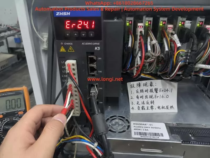
In field applications, the Zhishan K5 series AC servo drive may show the following symptom: the drive powers on normally, the servo can be enabled, forward rotation may work, but reverse rotation fails. Once a reverse command is given, the motor may not move, may move slightly and stop, or may immediately trigger Er24.1. In some cases, Er16.0 also appears.
This fault may look like a defective servo drive, but the real cause may be mechanical jamming, excessive load, abnormal encoder feedback, incorrect motor phase wiring, wrong direction logic, active reverse limit signal, brake not released, or improper parameter settings. To solve this problem correctly, the alarm meaning must be combined with the real machine behavior.
1. The Meaning of Er24.1: Excessive Speed Deviation
For the K5 servo drive, Er24.1 generally means excessive speed deviation protection. Speed deviation is the difference between the speed commanded by the drive and the actual speed fed back by the motor encoder.
For example, the PLC or motion controller sends a reverse rotation command to the servo drive. The drive outputs three-phase current to make the motor rotate in reverse. However, the encoder feedback shows that the motor speed does not reach the expected value, or the motor almost does not move. In this case, the drive determines that the difference between command speed and actual speed is too large. To prevent overcurrent, overload, mechanical impact, or loss of control, the drive stops and reports Er24.1.
Therefore, Er24.1 does not necessarily mean that the drive is internally damaged. More accurately, it means:
The drive has issued a motion command, but the actual motor movement does not match the expected result.
Common causes include:
motor blocked by mechanical load;
reverse direction mechanically jammed;
mechanical hard limit reached;
motor brake not released;
load inertia too large;
acceleration or deceleration time too short;
motor U/V/W wiring wrong or loose;
encoder cable loose or abnormal;
motor and drive not matched;
reverse direction signal logic incorrect;
speed deviation detection threshold set too small;
servo gain not suitable for the machine.
If the actual symptom is “forward rotation works, but reverse rotation fails,” the key point is not only speed deviation. The real question is:
Why does the motor fail to follow the command only in reverse direction?
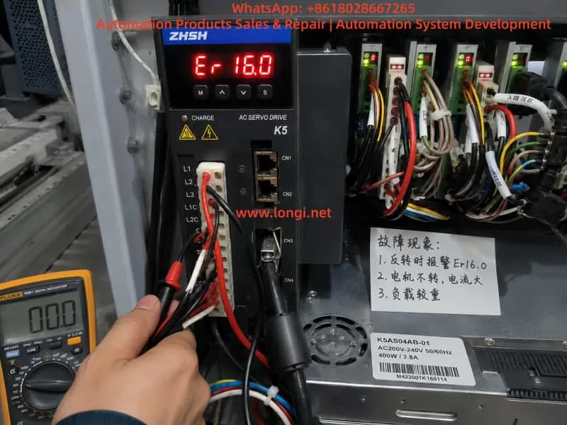
2. The Meaning of Er16.0: Overload Protection
Er16.0 is usually related to overload protection. Overload does not always mean an instant short circuit, and it does not always mean that the drive power module is damaged. In servo systems, overload usually means that the motor current has exceeded the allowed range for a certain period of time. The drive judges that the motor or drive is carrying excessive load.
If the machine is mechanically jammed in reverse direction, the drive will increase output current in an attempt to make the motor rotate. But because of mechanical resistance, brake locking, wiring error, or abnormal feedback, the motor cannot reach the target speed. This may first trigger Er24.1. If the high current continues, Er16.0 may also appear.
In other words, Er24.1 and Er16.0 are often connected:
A reverse command is given.
The motor cannot rotate correctly because of mechanical load, limit signal, brake, wiring, or feedback problem.
The drive increases output current.
The encoder feedback speed cannot follow the command.
The drive reports Er24.1.
If high current continues, the drive reports Er16.0.
Therefore, when Er24.1 appears together with Er16.0, do not treat them as two unrelated faults. The correct diagnostic logic is:
Find out why the motor cannot follow the command first, then determine whether overload is the cause or the result.
3. When Reverse Rotation Fails, Mechanical Problems Are Highly Suspect
In real repair work, if a servo system can rotate forward but cannot rotate backward, the mechanical side must be checked first. Many technicians immediately suspect the servo drive and replace it. However, after replacing the drive, the same alarm may still appear because the root cause is not in the drive.
Common mechanical causes include the following.
The first is one-direction mechanical jamming. Lead screws, guide rails, belts, chains, gearboxes, feeding wheels, and clamping mechanisms may move smoothly in one direction but become tight in the opposite direction. Lack of lubrication, damaged bearings, worn lead screw nuts, misaligned belts, damaged gearbox teeth, or foreign objects may all cause reverse movement failure.
The second is a mechanical hard limit. If the mechanism has reached the end position, and the limit switch or software limit does not stop the axis correctly, the servo may command movement against a dead stop. The motor receives torque command but cannot move. Current rises quickly, actual speed remains very low, and the drive reports an alarm.
The third is brake failure. If the servo motor has an electromagnetic brake, the brake must be released before motion. If the brake power supply is missing, the brake relay contact is damaged, the brake coil is faulty, or the brake mechanism is stuck, the motor may hum, vibrate, or fail to rotate. Sometimes the brake is not completely locked but only partially released. This is more difficult to detect because the motor may rotate at no load but fail under load.
The fourth is asymmetric load. Many machines do not have the same load in forward and reverse directions. Lifting mechanisms, feeding systems, pressing rollers, and clamping systems may have very different resistance depending on direction. If reverse direction happens to be the heavy-load direction, Er24.1 and Er16.0 may appear more easily.
For this reason, when a K5 servo drive reports Er24.1 or Er16.0 and the machine cannot reverse, do not start by changing parameters. First confirm whether the machine is mechanically able to move in reverse.
4. The Most Effective First Test: Disconnect the Load
The fastest way to separate mechanical problems from electrical problems is to disconnect the motor from the mechanical load. This means loosening the coupling, belt, gear connection, or other transmission connection so that the motor can run freely without load.
Do not test at high speed first. Use a low-speed jog command, such as 30 rpm, 50 rpm, or 100 rpm, and observe whether the motor rotates smoothly.
Check the following:
Can the motor rotate forward without load?
Can the motor rotate backward without load?
Does the motor vibrate during reverse rotation?
Does it make abnormal noise?
Does Er24.1 still appear?
Does Er16.0 still appear?
If the motor runs normally in both directions without load, the servo drive, motor, and encoder are probably not the main problem. The focus should move to mechanical load, brake, limit switch, or machine process.
If reverse rotation still triggers Er24.1 without load, the problem is more likely in motor wiring, encoder feedback, control signal, parameters, motor, or drive hardware.
This simple test is extremely valuable because it can quickly divide the fault into mechanical side or electrical side. Many servo faults take too long to repair because the technician keeps adjusting drive parameters without first separating the motor from the machine.
5. Check U/V/W Motor Wiring and Encoder Feedback
A servo motor is not the same as a normal three-phase induction motor. For a normal induction motor, changing two phases can reverse the direction. But for a servo motor, U/V/W phases cannot be changed randomly. The drive output phase sequence must correspond correctly to the encoder feedback angle. If the motor phase wiring is wrong, or if the encoder feedback direction does not match the drive output, the servo loop may become unstable.
Possible symptoms include vibration, no torque, excessive current, overcurrent, speed deviation alarm, or overload alarm.
The following points must be checked carefully:
U, V, and W are connected to the correct drive terminals;
motor cable has no broken wire;
terminal screws are tight;
connector pins are not bent or pushed back;
motor cable is not damaged;
encoder connector is fully inserted;
encoder cable shield is properly grounded;
encoder cable is not bundled together with power cables for a long distance;
motor and drive belong to the same axis;
motor cable and encoder cable are not crossed with another axis.
Multi-axis machines are especially prone to cable mix-up. For example, the motor power cable may belong to axis A, but the encoder feedback cable may be connected to axis B. Once the motor and encoder are not matched, the drive cannot close the loop correctly. The result may be immediate alarm, vibration, or dangerous motion.
If the fault appeared after repair, transportation, rewiring, motor replacement, or drive replacement, wiring error must be treated as a high-probability cause.
6. Check Reverse Limit and Inhibit Signals
“Cannot reverse” may also be caused by external control signals. A servo drive usually receives signals from a PLC, motion controller, or control board, including pulse command, direction signal, servo enable, positive limit, negative limit, emergency stop, alarm reset, and inhibit signals.
If the reverse direction limit signal is active, the drive may block movement in that direction. The field symptom may look like the motor cannot reverse, or it may stop immediately when reverse command is given.
Check these signals:
positive limit input;
negative limit input;
forward inhibit input;
reverse inhibit input;
emergency stop input;
servo enable input;
pulse input;
direction input;
PLC output logic;
control common wiring;
input terminal function assignment.
Some machines use normally closed limit logic, while others use normally open logic. If a limit switch, PLC output card, wiring, or parameter has been changed, the input logic may become inverted. The machine may not actually be at the negative limit, but the drive may think the negative limit is active, so reverse movement is blocked.
The correct method is not only to watch whether the limit switch moves mechanically. The technician must confirm the actual input status seen by the servo drive. This can be done through the drive monitor function or by measuring the terminal voltage with a multimeter.
7. Check Whether the Brake Is Released
If the servo motor has a holding brake, the brake circuit must be checked separately. Many technicians assume that the brake will automatically release when the servo is enabled, but in actual machines this is not always true.
The brake often requires an independent 24 VDC supply. It may be controlled by a relay, PLC output, or drive output. If the brake power supply is missing, the relay contact is burnt, the brake coil is damaged, or the brake mechanism is stuck, the motor will be forced to rotate against the brake.
Check the following:
brake rated voltage;
whether brake voltage appears after servo enable;
whether the brake makes a clear release sound;
whether the motor shaft can rotate freely after brake release;
whether brake power supply capacity is enough;
whether relay contacts are burnt;
whether brake coil is open or shorted;
whether brake gap is abnormal;
whether the brake is mechanically stuck.
If the brake is not released and the servo is forced to run, Er24.1 and Er16.0 can appear together. The drive outputs current, but the motor does not reach commanded speed. The result is speed deviation and overload.
8. Parameter Adjustment Should Not Be the First Solution
When technicians see speed deviation alarm, they may want to increase the speed deviation threshold. When they see overload alarm, they may want to increase acceleration time, reduce gain, or modify torque limit. Parameter adjustment can sometimes reduce false alarms, but it should not be used to hide a real mechanical or wiring problem.
If the mechanism is jammed, increasing the speed deviation threshold only delays the alarm. The motor may remain stalled for a longer time, causing motor overheating, drive damage, or mechanical deformation.
If U/V/W wiring or encoder feedback is wrong, parameter adjustment cannot solve the root problem. It may only make the fault more dangerous.
Parameter checking should be done after mechanical and wiring checks. Important parameter groups include:
speed deviation detection threshold;
speed deviation detection time;
acceleration time;
deceleration time;
speed loop gain;
position loop gain;
torque limit;
electronic gear ratio;
pulse input mode;
direction signal polarity;
motor capacity setting;
encoder-related settings;
positive and negative limit input assignment.
Do not restore factory parameters blindly. Machine builders may have set electronic gear ratio, limit logic, pulse mode, gain, and control mode according to the actual machine. A careless factory reset may make the machine unable to return to its original working condition.
9. How to Distinguish Drive Fault, Motor Fault, and External Fault
A practical diagnostic sequence should follow this order:
external mechanical system;
motor and encoder wiring;
control signals;
parameters;
drive and motor hardware.
If the motor runs normally without load but alarms under load, suspect mechanical load, brake, guide rail, lead screw, belt, gearbox, or machine jamming.
If forward works but reverse fails, suspect reverse mechanical resistance, negative limit, reverse inhibit, direction logic, or reverse acceleration impact.
If both forward and reverse vibrate or lack torque, suspect U/V/W wiring, encoder cable, motor matching, or servo gain.
If the alarm appears immediately after servo enable, suspect encoder fault, motor cable fault, drive power module, motor winding, brake locking, or serious parameter mismatch.
If the alarm appears randomly, suspect loose connectors, poor shield grounding, encoder interference, terminal contact problem, unstable power supply, or intermittent mechanical jamming.
If replacing the drive does not change the fault, the problem is probably not inside the drive. It is more likely in motor, encoder, wiring, mechanics, or control signal.
If replacing the motor solves the problem, the original motor may have encoder, winding, or brake failure.
If replacing the encoder cable solves the problem, the original cable or connector has a hidden fault.
If the same drive and motor work normally on a test bench but fail after installation, the machine mechanism or control logic must be checked.
10. Recommended Field Troubleshooting Procedure
For a Zhishan K5 servo drive showing Er24.1, sometimes with Er16.0, and failing to reverse, the following procedure is recommended.
First, record the alarm timing. Confirm whether the alarm appears at power-on, at servo enable, during forward rotation, or only during reverse rotation. The timing is more important than the alarm code alone.
Second, check whether the mechanism can move backward. With power off, manually rotate the transmission mechanism if possible. Check for tight points, hard stops, abnormal noise, brake locking, or one-direction resistance.
Third, disconnect the load and test the motor alone. Run forward and reverse at low speed. If the motor runs normally without load, focus on the mechanical side. If reverse still alarms without load, focus on wiring, feedback, control signal, or parameter.
Fourth, check the brake. If the motor has a brake, confirm that it is really released, not only that the control signal exists.
Fifth, check U/V/W and encoder wiring. Confirm motor phase wiring, encoder cable, shielding, connectors, and axis matching.
Sixth, check control input status. Focus on negative limit, reverse inhibit, emergency stop, servo enable, direction signal, and pulse command.
Seventh, check parameters. Confirm speed deviation threshold, acceleration and deceleration time, torque limit, direction polarity, pulse mode, electronic gear ratio, and limit input function assignment.
Eighth, test again at low speed. Start with no load, then light load, then normal load. Observe current, speed feedback, machine movement, and alarm behavior at each step.
Ninth, use substitution testing only when necessary. A same-model motor, encoder cable, or drive can be exchanged for comparison, but wiring and parameters must be confirmed before testing to avoid causing new damage.
11. Common Mistakes During Repair
Several mistakes are common when repairing this type of servo fault.
The first mistake is increasing the speed deviation threshold immediately after seeing Er24.1. This may hide mechanical jamming and cause more serious damage.
The second mistake is assuming the drive power module is bad after seeing Er16.0. Overload is often caused by load or motion conditions, not necessarily by drive hardware failure.
The third mistake is repeatedly testing the machine without disconnecting the load. If the mechanism is jammed, repeated testing sends high current into the motor and drive.
The fourth mistake is swapping U/V/W phases casually. A servo motor cannot be treated like a normal induction motor.
The fifth mistake is checking only the motor power cable and ignoring the encoder cable. Servo control is closed-loop. Encoder feedback problems can also cause speed deviation and overload.
The sixth mistake is looking only at the physical limit switch but not the drive input status. A switch may move correctly, but the drive terminal may receive the wrong signal.
The seventh mistake is restoring factory settings blindly. This may erase the original electronic gear ratio, limit logic, pulse mode, and gain settings.
The eighth mistake is ignoring the brake. A brake that does not fully release is a frequent cause of overload and speed deviation alarms.
12. Conclusion
When a Zhishan K5 series servo drive reports Er24.1, the core meaning is excessive speed deviation. When Er16.0 appears as well, the system also has an overload condition. For the symptom “reverse rotation failure,” the correct conclusion is not to immediately condemn the servo drive. The most likely causes are reverse-direction mechanical resistance, active reverse limit, brake not released, excessive load, abnormal encoder feedback, wrong wiring, or incorrect direction logic.
The correct repair method is to separate the mechanical side from the electrical side first. Disconnect the load and test forward and reverse rotation at low speed. If the motor works normally without load, check the mechanism, brake, and limit signals. If the alarm still appears without load, check U/V/W wiring, encoder cable, control terminals, direction command, and parameters.
Parameter adjustment should be used only after the real cause is identified. It should never be used to cover up mechanical jamming or wiring errors.
A servo alarm is the result of closed-loop monitoring. Er24.1 means the actual motor speed does not follow the command. Er16.0 means the motor or drive is overloaded. Only by analyzing command, feedback, current, mechanical load, and control signals together can the technician locate the fault quickly, avoid unnecessary part replacement, reduce downtime, and prevent further damage to the motor, drive, and machine mechanism.