
In modern industrial automation, a Variable Frequency Drive (VFD) is not only a speed controller but also the core of comprehensive motor protection. Among the Vacon (now Danfoss) series, F59 (Tmot unstable) is a highly representative fault code. Unlike the common “F16 Motor Overheat” error, F59 does not necessarily mean the motor is physically overheating; rather, it indicates that the monitoring signal itself is unreliable.
This article provides a deep technical analysis of the F59 fault, covering hardware principles, signal chains, software logic, and Electromagnetic Compatibility (EMC) to offer a practical guide for engineers.

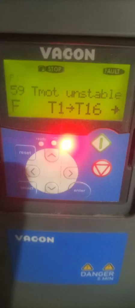
I. Definition and Essence of F59 “Tmot unstable”
In Vacon firmware, F59 represents “Motor temperature signal unstable.”
1. Fault Logic Mechanism
The inverter reads the resistance of temperature sensors (typically PT100, PT1000, or KTY84) installed in the motor windings via expansion I/O cards (such as OPT-BH or OPT-AF). The microprocessor (MCU) monitors this resistance at millisecond intervals.
If the MCU detects a drastic fluctuation in resistance that contradicts physical laws—for example, a temperature jump of more than 20°C within 100ms—the system deems the signal unstable and triggers F59. This prevents false protection or protection failure due to poor wiring.
2. Difference from F16
- F16 (Motor Overheat): The signal is stable, but the value exceeds the protection threshold (e.g., 150°C).
- F59 (Tmot unstable): The signal value itself is erratic, and the inverter cannot confirm the actual motor temperature.
II. Hardware Level: Sensors and Measurement Circuits
Understanding F59 requires knowing how the inverter “perceives” temperature.
1. Sensor Characteristics
Resistance Temperature Detectors (RTDs) are most common. For a PT100 sensor, the resistance at $0^\circ\text{C}$ is $100\Omega$, increasing by approximately $0.385\Omega$ per $1^\circ\text{C}$. When contact resistance or electromagnetic noise is superimposed on the circuit, the measured value oscillates, inducing F59.
2. Vacon Expansion Cards
The display showing T1->T16 suggests a multi-channel temperature acquisition module. Vacon NXP/NXS series often use the OPT-BH module. Because measurement signals are usually at the millivolt (mV) level, they are highly susceptible to interference from high-frequency carrier frequencies.
III. Four Core Causes of F59 Faults
Based on engineering practice, F59 faults generally stem from four dimensions:
1. Physical Connection: Fatigue and Contact Resistance
- Loose Terminals: In high-vibration environments, terminals may loosen, causing instantaneous resistance changes.
- Shielding Failure: If the cable shield is not grounded correctly (e.g., using a long “pig-tail” instead of a 360-degree clamp), shielding effectiveness drops significantly at high frequencies.
2. Environmental Interference: EMC
- Common Mode Coupling: High $dv/dt$ from the inverter output can couple into sensor cables. Without twisted-pair shielded cables, this noise causes sampling errors.
- Carrier Interference: High carrier frequencies (e.g., >10kHz) combined with short sampling filter times can lead the MCU to misidentify noise as temperature spikes.
3. Hardware Aging
- Slot Oxidation: Oxidation between the OPT-BH card and the control board can cause transient communication interruptions.
- Capacitor Degradation: Aging filter capacitors on the expansion card lose their ability to suppress high-frequency noise.
4. Configuration: Floating Channels
If channels are activated in the software (e.g., T1->T16) but have no physical sensor attached or no matching resistor, induced voltages on these floating channels can interfere with active channels.
IV. Diagnostic Process: Step-by-Step Elimination
Step 1: Static Resistance Test
- Power down the inverter and wait 5 minutes.
- Disconnect sensor leads and measure resistance with a multimeter.
- Reference: At $20^\circ\text{C}$, a PT100 should be approx. $107.7\Omega$.
- Stability: If the value jumps wildly while the motor is static, the sensor or cable is damaged.
Step 2: Signal Loop and Shielding
- Ensure sensor cables are not parallel to power cables (maintain >30cm gap).
- Key Test: Replace the motor sensor at the inverter terminals with a fixed precision resistor (e.g., $110\Omega$).
- If the fault disappears, the problem is in the external cable or motor.
- If the fault persists, the problem is the expansion card or internal logic.
Step 3: Software Parameter Adjustment
- Temperature Signal Filtering: Increase the filter time constant (e.g., from 1.0s to 3.0s) to smooth out transient pulses.
- Unused Channels: Deactivate any monitored channels that do not have sensors connected.
V. Preventive Measures
- Proper Grounding: Use single-ended grounding for sensor signals. The shield should have large-area contact with the inverter chassis via a metal clamp.
- Signal Conversion: For distances over 50 meters, use a signal transmitter to convert PT100 signals to 4-20mA, which is much more noise-resistant.
- Routine Maintenance: Periodically re-seat expansion cards to break through oxidation layers on pins.
Conclusion
The F59 Tmot unstable code is a warning regarding signal integrity. As seen in the provided image, the drive is in a STOP state with the red fault light active, indicating the issue exists even when the motor is not running. By focusing on physical connections, EMC shielding, and proper filtering, this technical hurdle can be efficiently resolved to ensure stable production.