
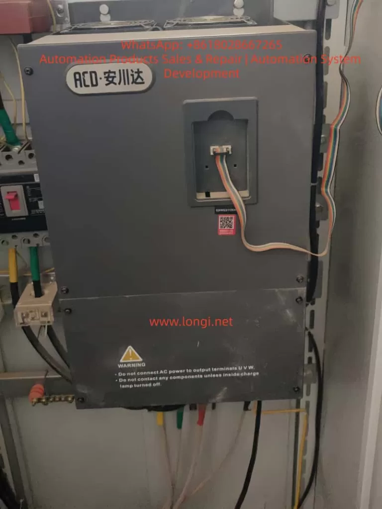
In industrial applications, ACD 900 Series (M900) variable frequency drives are widely used in fans, pumps, conveyors, and general automation systems. A common field issue reported after a period of normal operation is:
The drive runs for several hours or even more than ten hours, then suddenly trips with ERR05, and the shutdown timing is irregular.
This type of fault is often misinterpreted as random failure or unstable electronics. In reality, it is a deterministic energy management problem that develops over time due to component aging, thermal effects, and load behavior.
This article provides a detailed engineering-level analysis of ERR05 faults in ACD 900 Series VFDs, along with practical diagnostic steps and permanent solutions.
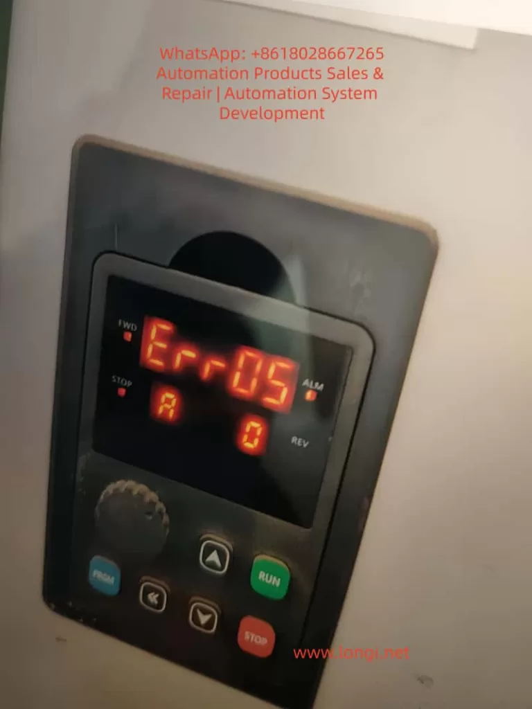
1. What ERR05 Really Means in ACD 900 Series
According to the manual, ERR05 is defined as:
Acceleration Overvoltage
However, this definition is misleading in real-world scenarios.
From an engineering standpoint, ERR05 should be understood as:
DC bus overvoltage caused by regenerative energy that cannot be dissipated
In other words:
- ERR05 is not only related to acceleration
- ERR05 is primarily a regenerative overvoltage condition
2. Internal Mechanism of Overvoltage
The internal energy flow of the ACD 900 VFD is:
- AC input → Rectifier → DC bus (~540V for 380V systems)
- DC bus → IGBT inverter → Motor
During certain operating conditions:
- Deceleration
- Load inertia release
- External force driving the motor
The motor acts as a generator:
Mechanical energy → Electrical energy → Fed back into DC bus
If this energy has no discharge path:
→ DC bus voltage rises
→ Protection threshold exceeded
→ ERR05 triggered
3. Key Characteristics of This Case
Based on the field description:
- The drive has been used for a period (not new)
- Fault appears after several hours
- Fault timing is irregular
- No fault at startup
These characteristics clearly indicate:
This is NOT a parameter or wiring issue, but a degradation or dynamic condition problem
4. Four Major Root Causes (Ranked by Probability)
4.1 DC Bus Capacitor Aging (Primary Cause)
The ACD 900 series uses electrolytic capacitors for DC bus energy storage.
Over time, capacitors degrade:
- Capacitance decreases
- ESR (Equivalent Series Resistance) increases
- Heat generation increases
Consequences:
- Reduced ability to absorb regenerative energy
- Increased voltage fluctuation
Result:
Conditions that were previously safe now trigger overvoltage
This is the most common reason why:
- The system worked before
- But starts failing after months or years
4.2 Braking Resistor or Braking Unit Failure
In normal design:
- Regenerative energy is dissipated through a braking resistor
- Connected between “+” and “PB” terminals
Typical failures:
- Open circuit braking resistor
- Loose wiring
- Damaged braking transistor (IGBT)
- Resistance value drift
If the braking circuit fails:
Regenerative energy accumulates in DC bus → inevitable overvoltage
This matches the symptom:
- Random trips
- Load-dependent behavior
4.3 Thermal Effects and Cooling Degradation
The delayed fault (after hours) strongly suggests thermal influence.
Over time:
- Cooling fans slow down or fail
- Heat sinks accumulate dust
- Internal temperature rises
Effects:
- Capacitor ESR increases further
- Voltage sensing drifts
- IGBT switching characteristics change
Result:
System becomes unstable under thermal conditions
4.4 Load Condition Changes (Often Ignored)
In many cases, the VFD is not the root cause.
Typical mechanical causes:
- Fan reverse airflow
- Pump backflow
- Increased inertia (belt, flywheel)
- Mechanical looseness
These cause:
Motor enters regenerative mode unexpectedly
5. Why the Fault Appears Random
ERR05 is triggered only when multiple factors coincide:
- High DC bus voltage
- Certain load condition
- Elevated temperature
- Slightly higher supply voltage
Only when all conditions align:
Threshold exceeded → trip occurs
Therefore, the fault appears:
- Intermittent
- Non-repeatable at fixed times
- “Random” to operators
But in reality:
It is a predictable physical process
6. Field Diagnostic Procedure (Practical Approach)
Step 1: Monitor DC Bus Voltage
Check monitoring parameters:
- Normal: ~540V (380V system)
- Before trip: rises significantly
If confirmed:
✔ Regenerative overvoltage
Step 2: Check Braking Resistor
After power off:
- Measure resistance
- Check for open circuit
Also verify:
- Wiring at + / PB terminals
- Physical condition (burn marks)
Step 3: Increase Deceleration Time
Parameter:
- Deceleration time (e.g., F0-05)
Action:
- Increase 2–3 times
Result:
- If fault disappears → regeneration issue confirmed
Step 4: Inspect Cooling System
Check:
- Fan operation
- Dust accumulation
- Cabinet ventilation
Step 5: Measure Input Voltage
Record:
- Line voltage level
- Voltage fluctuations
If consistently high:
→ reduced safety margin
Step 6: Run Without Load
Disconnect mechanical load:
- No fault → mechanical issue
- Still fault → electrical issue
7. Engineering Solutions (From Temporary to Permanent)
Solution 1: Increase Deceleration Time (Temporary)
Advantages:
- Easy implementation
- Immediate effect
Disadvantages:
- Slower process response
- Not a root fix
Solution 2: Install or Replace Braking Resistor (Recommended)
Advantages:
- Directly handles regenerative energy
- Most effective solution
Solution 3: Replace DC Bus Capacitors (Permanent Fix)
Applicable when:
- Equipment has long service time
- Capacitor degradation confirmed
Solution 4: Improve Cooling System
Actions:
- Clean heat sinks
- Replace fans
- Improve cabinet airflow
Solution 5: Optimize Mechanical System
Examples:
- Prevent reverse driving
- Reduce inertia
- Improve load stability
8. Is Main Board Failure Possible?
Main board faults typically show:
- Immediate fault after power-on
- Repeatable and stable error
In this case:
- Delayed occurrence
- Load-dependent behavior
Conclusion:
Main board failure is unlikely and should NOT be the first assumption
9. Final Engineering Conclusion
ERR05 faults in ACD 900 Series VFDs, especially after a period of operation, are not random failures but a result of energy imbalance in the system.
Core mechanism:
Regenerative energy generation → Reduced absorption capability (capacitor aging / braking failure) → DC bus voltage rise → ERR05 trip
Recommended troubleshooting priority:
- Braking circuit condition
- DC bus capacitor health
- Cooling system
- Load behavior
Only by addressing the system as a whole can the issue be permanently resolved, rather than relying on repeated parameter adjustments or component replacement.