
Foreword
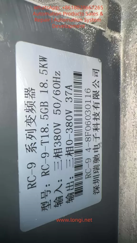
The Ruichi RC-9 series, a high-performance vector-type inverter launched by Shenzhen Ruichi Electronics, is widely used in various industrial automation scenarios such as textiles, machine tools, building materials, fan and pump systems, and lifting and conveying systems. It features both V/F and vector control modes, a wide speed regulation range, high starting torque, and rich networking capabilities. Among them, the RC-9-T18.5GB model with an 18.5kW rating is a core device in small- to medium-power industrial drive systems.
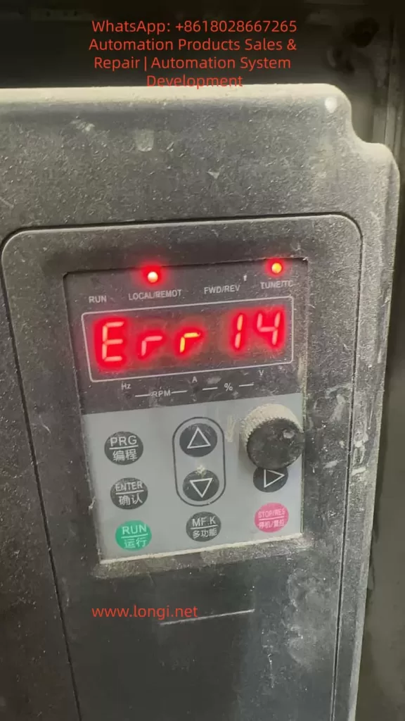
During long-term operation in the field, the ERR14 fault code is one of the most frequently occurring fault types in the RC-9 series inverters. This fault represents overheating protection for the inverter’s core power device module. Once triggered, the inverter immediately blocks its output and shuts down for protection, which not only directly interrupts the production process but also causes permanent degradation or even breakdown of the IGBT (Insulated Gate Bipolar Transistor) inverter module due to repeated overheating impacts. In severe cases, it can lead to catastrophic failures such as inverter explosions.
Based on the technical specifications in the official user manual of the RC-9 series inverters and combined with practical maintenance experience in industrial settings, this article provides an in-depth analysis of the underlying triggering logic and core causes of the ERR14 fault. It establishes a standardized, step-by-step troubleshooting and resolution process and proposes a systematic preventive maintenance plan. This guide offers directly applicable technical guidance for equipment maintenance personnel to fundamentally reduce the occurrence probability of this fault and ensure the long-term stable operation of drive systems.
I. Core Definition and Underlying Protection Logic of the ERR14 Fault
In the fault code system of the Ruichi RC-9 series inverters, ERR14 is officially defined as an inverter module overheating fault. It represents a hardware + software dual-level protection mechanism implemented by the inverter for the core power device, the IGBT. This fault is classified as a highest-priority shutdown protection type.
The IGBT module is the core component of the inverter responsible for converting alternating current (AC) to direct current (DC) and then back to adjustable-frequency and adjustable-voltage AC power. During its operation, two primary types of losses occur: conduction losses when the IGBT is in the conducting state and switching losses during state transitions. All these losses are ultimately dissipated in the form of heat. As a semiconductor power device, the performance and lifespan of an IGBT are directly related to its operating temperature. The industry consensus is that for every 10°C increase in the IGBT junction temperature, the device’s lifespan is halved. When the junction temperature exceeds the chip’s rated tolerance threshold, it directly causes irreversible thermal breakdown of the chip, leading to permanent damage to the module.
Based on this, the RC-9 series inverters integrate high-precision NTC (Negative Temperature Coefficient) thermistors within the IGBT module. Through the sampling circuit on the drive board, the module’s case temperature data is continuously collected and transmitted to the main control board for real-time monitoring. The factory-default module overheating protection threshold for the inverter is set at 75°C (adjustable within the range of 0-100°C via function code P8-47). When the temperature sampling circuit detects that the IGBT module temperature reaches the protection threshold, the main control board immediately triggers the ERR14 fault protection, blocks the IGBT drive signals, stops the inverter output, activates the fault relay, illuminates the fault indicator on the panel, and displays the ERR14 fault code, providing rapid protection for the IGBT module.
It is important to note that ERR14 faults can be categorized into two types: genuine overheating faults triggered by actual overheating of the IGBT module and false alarms caused by abnormalities in the temperature sampling circuit. The former results from the actual temperature of the IGBT module exceeding the limit, while the latter is caused by incorrect protection triggered by damage to the temperature sensing element or the sampling circuit. The troubleshooting approaches for these two types are entirely different, and this distinction is a common source of misjudgment in field maintenance.
II. In-Depth Analysis of the Five Core Causes of ERR14 Module Overheating Faults
Based on the hardware design, user manual specifications, and field maintenance data of the RC-9 series inverters, the triggering of ERR14 faults can be attributed to five core causes that cover the entire chain of factors from the external environment and mechanical cooling to electrical parameters and hardware components. Over 80% of these faults are concentrated in the first three external and cooling-related causes.
(I) Excessive Operating Environment Temperature Exceeding Inverter Design Tolerance
The standard designed operating environment temperature range for the RC-9 series inverters is -10°C to 50°C, with a maximum allowable ambient temperature of 50°C under rated load conditions. When the ambient temperature exceeds this range, the inverter’s cooling capacity drops sharply, directly causing overheating of the IGBT module and triggering the ERR14 fault.
Common scenarios where the ambient temperature exceeds the limit include:
- The inverter is installed inside a closed electrical control cabinet without a properly designed cooling air duct or without additional cooling equipment such as cooling fans or air conditioners. The heat generated by the inverter’s operation accumulates continuously within the cabinet, creating a “heat island effect.” In high-temperature workshops during summer, the cabinet temperature can easily exceed the 50°C threshold.
- Multiple inverters are stacked vertically inside the cabinet without installing thermal insulation and airflow guide plates as specified in the manual. The hot air exhausted by the lower inverter is directly drawn into the air intake of the upper inverter, creating a hot air circulation loop that renders the cooling system ineffective.
- The inverter is installed in a location exposed to direct sunlight or near external heat sources such as boilers, heating furnaces, or resistance boxes, causing the ambient temperature to rise passively.
- The installation site has high humidity or corrosive gases, which not only accelerate device aging but also reduce insulation performance, indirectly increasing device leakage currents and exacerbating heat generation.
According to the installation specifications for the RC-9 series inverters, for models with a rated power greater than 22kW, a vertical installation spacing of ≥200mm is required. For models with a rated power of 18.5kW and below, a vertical spacing of ≥100mm and sufficient lateral cooling space are required. Field maintenance data shows that non-compliance with these installation specifications and poor environmental cooling conditions are the most common诱因 (causes) for ERR14 faults.
(II) Blocked Cooling Air Duct, Sharp Decline in Heat Sink Heat Exchange Efficiency
The RC-9 series 18.5kW model adopts a cooling structure consisting of an IGBT module in direct contact with an aluminum heat sink and a bottom-mounted axial fan for forced air cooling. The designed air duct follows a bottom-in, top-out pattern, where the fan drives air to flow through the heat sink fins, carrying away the heat generated by the IGBT module. The heat exchange efficiency of the heat sink directly determines the effectiveness of temperature control for the IGBT module, and air duct blockage is the most common cooling failure issue in the field.
In scenarios with high levels of dust, cotton fibers, or metal chips, such as cement and building materials production, textile and chemical fiber manufacturing, mining, and woodworking, the inverter continuously operates, and airborne particulate matter continuously adheres to the spaces between the heat sink fins and the air intake filter screen. Especially for the 18.5kW model, which has relatively small fin spacing on the heat sink, the fins can easily become completely blocked by particulate matter, forming a “thermal insulation layer.” In this case, even if the fan operates normally, air cannot flow through the heat sink fins to form convection, causing the heat exchange efficiency of the heat sink to drop by over 80%. The heat generated by the IGBT module cannot be dissipated, and its temperature can rise rapidly to the protection threshold within a few minutes, triggering the ERR14 fault.
Additionally, when oil and moisture adhere to the surface of the heat sink, they combine with dust to form oil sludge, which not only blocks the air duct but also significantly reduces the thermal conductivity of the heat sink, further worsening the cooling effect. This is a core cause of ERR14 faults in scenarios with high levels of oil and grease, such as food processing and metalworking.
(III) Failure of the Cooling Fan System, Complete Loss of Forced Air Cooling Function
The cooling fan is the core power component of the forced air cooling system in the RC-9 series inverters, and its operating status directly determines the effectiveness of the cooling system. According to the user manual’s specifications for replacing consumable parts, the designed service life of the cooling fan is 2-3 years. After long-term operation, the fan is prone to aging and failure, making it a high-frequency诱因 (cause) of ERR14 faults.
The main forms of cooling fan system failure include:
- Wear and aging of the fan bearings, resulting in reduced rotational speed, shutdown, abnormal noise during operation, and a significant decrease or complete loss of air volume. As a result, the heat sink cannot form effective convection.
- Severe dust accumulation on the fan blades, fractures, or defects, causing a loss of dynamic balance and substandard air pressure and volume that cannot meet the cooling requirements of the heat sink.
- Faults in the fan power supply circuit, including loose or oxidized connection terminals, blown fuses in the power supply, or damage to the fan power supply circuit on the drive board, preventing the fan from starting up when powered on.
- Incorrect settings for the fan control parameters. The RC-9 series inverters use function code P8-48 to set the cooling fan control mode, with a factory default value of 0 (fan operates during inverter operation). If it is mistakenly set to other modes, the fan may not start up when the inverter is running, directly causing an overheating fault. If it is set to 1 (fan always operates) for an extended period, it accelerates bearing aging and shortens the fan’s service life.
Field maintenance data shows that for RC-9 series inverters with an operating life exceeding 2 years, failures caused by fan issues account for over 60% of ERR14 faults. Moreover, most of these faults are preceded by warning signs such as abnormal fan noise or reduced rotational speed, which are often not addressed in a timely manner during maintenance.
(IV) Abnormalities in the Temperature Sampling Circuit, Triggering False Overheating Alarms
If the inverter triggers the ERR14 fault under low-temperature environmental conditions or during no-load operation, and no abnormalities are found in the heat sink or fan, there is a high probability of abnormalities in the IGBT module’s temperature sampling circuit, causing the main control board to receive incorrect high-temperature signals and trigger false protection. This is a cause that is easily overlooked and prone to misjudgment in field maintenance, leading many maintenance personnel to mistakenly conclude that the module is damaged and incur unnecessary costs for replacing spare parts.
The temperature sampling circuit in the RC-9 series inverters consists of three parts: the NTC thermistor built into the IGBT module, connection terminals and wiring harnesses, and the temperature sampling circuit on the drive board and main control board. Abnormalities in any of these parts can lead to incorrect temperature sampling.
- Damage or aging of the NTC thermistor: The NTC thermistor is a negative temperature coefficient device with a nominal resistance of mostly 10kΩ at a normal temperature of 25°C. After long-term operation at high temperatures, it may experience resistance drift, open circuits, or short circuits. If the resistance becomes abnormally low, it will transmit false high-temperature signals to the main control board, triggering a false ERR14 alarm.
- Faults in the wiring and transmission circuit: Loose or oxidized connection terminals of the thermistor, broken wires, or poor contact in the 32-pin wiring harness between the drive board and the main control board can interrupt or distort the temperature sampling signals, causing false alarms.
- Hardware damage in the sampling circuit: Faults in the temperature sampling circuit on the drive board or main control board, including changes in the values of sampling resistors, damage to operational amplifiers, or failure of filtering capacitors, can lead to abnormal temperature sampling data and trigger protection actions.
(V) Performance Degradation/Damage of the IGBT Inverter Module Itself, Exacerbating Abnormal Heat Generation
When all the above external factors have been ruled out and the ERR14 fault still occurs frequently, the core cause is performance degradation or physical damage to the IGBT inverter module itself, resulting in significantly higher heat generation than normal during operation and triggering overheating protection.
The degradation and damage of IGBT modules mainly result from the following scenarios:
- Long-term operation under heavy loads and frequent starting and stopping, especially when the 18.5kW inverter is used for impact loads such as cranes, mixers, and wire drawing machines. The IGBT is subjected to high current impacts for extended periods, causing fatigue in the chip solder layer, a significant increase in thermal resistance, and an inability to transfer heat to the heat sink effectively, leading to a rapid rise in junction temperature.
- Previous occurrences of output short circuits, motor-to-ground short circuits, overcurrent faults, or other issues in the inverter, which caused hidden damage to the IGBT chip. Although these incidents may not directly cause an explosion, they significantly increase the chip’s on-resistance. Under the same load current, the conduction losses increase exponentially, leading to a sharp increase in heat generation.
- Aging of the freewheeling diodes within the module, resulting in a significant increase in reverse leakage current and generating additional heat.
- Drying out or脱落 (detachment) of the thermal conductive silicone grease between the module and the heat sink, or loosening of the fixing screws, creating air gaps between the module and the heat sink and causing a sharp increase in thermal resistance, rendering the cooling ineffective.
The performance degradation of IGBT modules is irreversible. If not addressed promptly, not only will ERR14 faults occur frequently, but it will eventually lead to module breakdown, inverter explosions, and even damage to core components such as the main control board and drive board, resulting in greater economic losses.
III. Step-by-Step Troubleshooting and Standardized Resolution Process for ERR14 Faults
In response to the five core causes of ERR14 faults, we have developed a step-by-step troubleshooting and resolution process that progresses from easy to difficult, from external to internal factors, and from low-cost to high-cost solutions. This process fully complies with the maintenance logic in industrial settings, helping maintenance personnel quickly locate the root cause of the fault, resolve issues efficiently, and strictly adhere to the safety operation specifications of the RC-9 series inverters to avoid risks such as electric shock and secondary damage to the equipment.
Step 1: Initial Fault Assessment and Safety Operation Specifications (Prerequisite)
After the inverter triggers the ERR14 fault, the following operations must be performed first. Repeated resetting or forced starting and operation are strictly prohibited to avoid exacerbating the fault:
- Press the STOP/RES (stop/reset) button on the inverter panel to confirm that the inverter is in a stopped state. Then, disconnect the air circuit breaker on the input side of the inverter to completely cut off the input power supply.
- Strictly adhere to the safety specifications in the user manual. After powering off, wait at least 2 minutes to allow the bus capacitors inside the inverter to fully discharge. Confirm that the CHARGE indicator is off or use a multimeter to measure that the bus voltage is below AC36V before opening the cover for operation to eliminate the risk of electric shock.
- Record key fault information, including the operating conditions when the fault was triggered (no-load/full-load, starting process/stable operation/deceleration process), ambient temperature, operating life of the inverter, past maintenance records, and the operable duration after fault reset. This information provides direction for subsequent troubleshooting.
Step 2: Inspection and Rectification of External Environment and Installation Compliance
This step is the priority for troubleshooting and does not require disassembly of the inverter itself. It can resolve most environment-related faults. The core inspection and rectification content is as follows:
- Ambient temperature measurement and rectification: Use a temperature gun to measure the ambient temperature inside the inverter control cabinet and confirm whether it exceeds 45°C. If it approaches or exceeds the 50°C threshold, take immediate rectification measures: Install axial cooling fans or industrial air conditioners in closed control cabinets, remove heat-generating devices from the cabinet, avoid direct sunlight on the inverter, keep it away from external heat sources, and ensure that the cabinet’s ambient temperature remains stable below 40°C.
- Compliance check for installation specifications: Check whether the inverter is installed vertically and strictly prohibit inversion or tilting beyond 5°, as this will affect air duct convection. Confirm whether sufficient cooling space is reserved above, below, and to the sides of the inverter. For the 18.5kW model, a vertical spacing of ≥100mm and a lateral spacing of ≥50mm are required. When multiple inverters are installed vertically in a stack, thermal insulation and airflow guide plates must be installed to avoid hot air circulation.
- Inspection for obstructions at air inlets and outlets: Clear any obstructions at the air inlets and outlets of the inverter and replace clogged air intake filters to ensure smooth air intake and exhaust in the air duct.
Step 3: Inspection and Maintenance of the Cooling Air Duct and Fan System
This step is the core环节 (part) for resolving ERR14 faults, and over 80% of the faults in the field can be resolved through this step. The specific operations are as follows:
- Thorough cleaning of the cooling air duct: After the inverter is powered off and discharged, remove the top and bottom covers. Use dry compressed air with a pressure ≤0.6MPa to blow dust, cotton fibers, and metal chips out of the heat sink fins from the air outlet towards the air inlet. If there is oil and grease on the heat sink surface, wipe it clean with anhydrous alcohol and allow it to dry completely before reinstalling the covers.
- Comprehensive inspection and replacement of the cooling fan:
- Visual inspection: Check for fractures or dust accumulation on the fan blades, abnormal noise from the bearings, and loose or aged connection terminals.
- Power-on testing: After reinstalling the safety covers and powering on, set function code P8-48 to 1 to force the fan to operate continuously. Check whether the fan starts up normally, feel the air volume at the air outlet with your hand, and use a tachometer to measure the fan speed to confirm whether it meets the rated specifications.
- Fault handling: If the fan does not rotate, first troubleshoot the power supply circuit and wiring connections, then inspect the fan itself and replace any damaged fans with ones of the same specifications immediately. If the fan has been in operation for more than 2 years, even if it is temporarily operating normally, preventive replacement is recommended to avoid sudden failures in the future.
- Verification after rectification: After completing the cleaning and fan replacement, restore the inverter’s normal wiring connections, power it on, and run it under no-load conditions. Monitor the IGBT module temperature through the monitoring parameters in the U0 group on the inverter panel. Under normal ambient conditions, the no-load temperature should be 10-20°C higher than the ambient temperature and stabilize between 40-60°C.
Step 4: Inspection and Optimization of Load and Operating Parameter Rationality
If the cooling system is functioning normally but the inverter still triggers the ERR14 fault under load, it is necessary to inspect whether the load conditions and operating parameter settings are reasonable to eliminate additional heat generation caused by improper parameters or overloading:
- Load current monitoring and overloading inspection: Check the inverter’s output current (monitoring parameter U0-02) through the panel. The rated output current of the RC-9-T18.5GB model is 37A. If the operating current consistently exceeds 90% of the rated value, it indicates heavy-load or overloading operation, which is a core诱因 (cause) of IGBT heat generation. Immediately inspect whether the motor is experiencing stalling, whether the mechanical load is jammed, whether the transmission mechanism is faulty, and whether the inverter selection matches the load. Resolve mechanical faults, reduce the load, and if the inverter is undersized, replace it with a model of a higher power rating.
- Optimization of carrier frequency parameters: The carrier frequency is set by function code P0-15. A higher carrier frequency reduces motor noise but increases the switching losses of the IGBT, resulting in higher heat generation. For scenarios with high ambient temperatures and frequent ERR14 faults, the carrier frequency can be appropriately reduced within an acceptable range of motor noise. For the 18.5kW model, it can be lowered from the factory default of 8kHz to 4-5kHz, significantly reducing the IGBT’s switching losses and heat generation.
- Optimization of motor parameters and control modes: If the inverter is operating in vector control mode (SVC/VC) and motor parameter auto-tuning has not been performed, it will result in insufficient control accuracy, large current fluctuations, and increased additional heat generation. Strictly follow the steps in Section 4.2 of the user manual to perform complete tuning (set P1-37=2) with the motor and load completely decoupled. If decoupling the load is not possible, perform static tuning (set P1-37=1) to ensure that the motor parameters match the actual operating conditions and reduce operating current and heat generation.
- Optimization of V/F curves and torque boost: For V/F control mode, if the torque boost parameter P3-03 is set too high, it will result in excessive no-load current for the motor and increased IGBT heat generation. For square torque loads such as fans and pumps, set P3-02 to 2 (square V/F curve) and reduce the manual torque boost value to eliminate additional losses and heat generation at low speeds.
Step 5: Inspection of Temperature Sampling Circuit Abnormalities and Handling of False Alarm Faults
If the inverter triggers the ERR14 fault under low-temperature and no-load conditions and no abnormalities are found in the above steps, it is necessary to inspect the temperature sampling circuit to resolve false alarm faults:
- Inspection of the NTC thermistor: After the inverter is powered off and discharged, unplug the NTC thermistor connector from the IGBT module. Use a multimeter’s resistance range to measure the NTC resistance at a normal ambient temperature of 25°C. If the resistance is 0, infinite, or deviates by more than 30% from the nominal 10kΩ, it indicates that the NTC thermistor is damaged and needs to be replaced with one of the same specifications. If the NTC is built into the IGBT module, the entire IGBT module must be replaced.
- Inspection of wiring and transmission circuits: Check for broken wires, loose connections, or oxidation in the wiring of the thermistor. Clean the connection terminals and tighten them. Unplug and replug the 32-pin wiring harness between the drive board and the main control board and clean the oxidation on the harness pins to ensure normal transmission of temperature sampling signals.
- Inspection of sampling circuit hardware: If the NTC and wiring are normal but false alarms still occur, it indicates that the temperature sampling circuit on the drive board or main control board is damaged and needs to be replaced with the corresponding drive board or main control board. It is recommended to contact the manufacturer’s technical support to complete this operation to avoid secondary damage caused by self-repair.
Step 6: Inspection and Replacement of the IGBT Module Itself
If all the above steps have been completed and the inverter’s temperature still rises rapidly and triggers the ERR14 fault under load, it indicates that the IGBT module has undergone irreversible performance degradation or damage and requires module inspection and replacement:
- Static inspection of the IGBT module: After the inverter is powered off and discharged, disconnect the input R, S, T and output U, V, W terminals. Use a multimeter’s diode range to measure the diode characteristics of the three-phase upper and lower bridge arms of the IGBT module. Under normal conditions, there should be a forward conduction voltage drop of 0.3-0.7V and reverse blocking. If forward and reverse conduction or blocking occur, or if the voltage drop differences between the three-phase bridge arms exceed 0.2V, it indicates that the module is damaged and must be replaced.
- Standardized replacement operation for the module: When replacing the IGBT module, first thoroughly clean the old thermal conductive silicone grease from the surface of the heat sink. Apply a new layer of thermal conductive silicone grease with a thermal conductivity of ≥1.2W/m·K evenly on the contact surface between the module and the heat sink, ensuring no air bubbles or impurities. Tighten the module fixing screws in a diagonal sequence with the specified torque to avoid module warping and increased thermal resistance. After replacement, first perform a static test to confirm no short circuits, then conduct a no-load test and a rated load test to ensure that the inverter operates normally with no fault alarms and a stable temperature.
IV. Systematic Preventive Maintenance Plan for ERR14 Module Overheating Faults
The core essence of the ERR14 fault is “overheating,” and the vast majority of these faults can be fundamentally avoided through standardized preventive maintenance. Based on the user manual specifications of the RC-9 series inverters and practical maintenance experience in industrial settings, we have developed a full-lifecycle preventive maintenance plan that can significantly reduce the occurrence probability of ERR14 faults and extend the service life of inverters.
(I) Establish a Graded Regular Maintenance System
- Daily inspections: During equipment operation, check whether the module temperature and output current displayed on the inverter panel are normal, whether the cooling fan is operating smoothly without abnormal noise, whether the ambient temperature inside the control cabinet exceeds the limit, and whether the motor is operating with abnormal noise or vibration. If any abnormalities are found, stop the equipment immediately for inspection.
- Monthly maintenance: Use dry compressed air to clean the dust on the surface of the inverter and inside the control cabinet. Check whether the air inlet and outlet filters are clogged and clear any debris. Check for loose or overheated and discolored connection terminals in the main and control circuits and tighten them promptly. Verify that the inverter’s operating parameters have not been modified incorrectly.
- Quarterly maintenance: After disconnecting the power and discharging, open the cover to clean the dust accumulation on the heat sink fins and fan. Inspect the operating status of the fan and replace any bearings with abnormal noise in advance. Measure the static characteristics of the IGBT module and verify the sampling accuracy of the temperature sampling circuit to ensure normal temperature detection.
- Annual maintenance: Perform a comprehensive disassembly and cleaning of the inverter. Replace cooling fans that have been in operation for 2 years. Inspect the bus electrolytic capacitors for bulging or leakage and perform preventive replacement for those that have reached