
The AUT-DRIVE DVA series high-function, low-noise general-purpose inverters employ high-quality components and the latest microcomputer control technology. They are widely applicable to constant torque (G-type) and fan/pump (P-type) loads. This guide, based on the AUT-DRIVE Inverter DVA Series User Manual (59 pages), focuses on practical operational needs and provides comprehensive and highly practical technical guidance. The content covers the use of the operation panel, parameter management, external terminal control, and fault diagnosis and troubleshooting, helping users install, commission, and maintain the inverter safely and efficiently. All operations must comply with the safety warnings in the manual: Cut off the power supply before wiring, never touch high-voltage components, and ensure proper grounding.
I. Introduction to Digital Operation Panel Functions
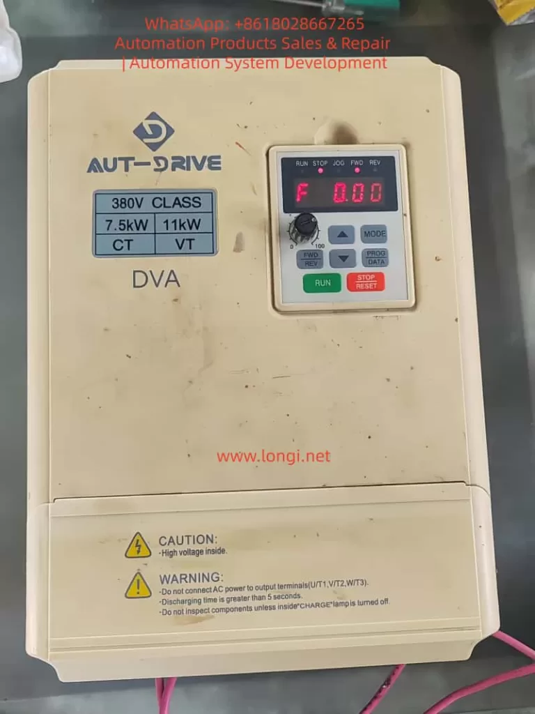
The DVA series comes standard with either the LC-A05E (suitable for the low-power range DVA-2S0004G to DVA-4T0110G) or the LC-A20E (for the high-power range) digital operator, which is installed on the upper cover of the inverter. The panel is divided into a display area and a key control area.
Display Area
- LED digital tubes display the current status, including the set frequency (F xxxx), actual output frequency (H xxxx), load current (A xxx), user-defined physical quantities, counter values, parameter group/value, forward/reverse commands (Fwd/rEu), and external abnormalities (EF).
- LED indicators display the RUN (running), STOP (stopped), JOG (jogging), FWD (forward rotation), and REV (reverse rotation) statuses.
Key Control Area (Taking LC-A05E as an example)
- MODE: Switch the display mode (e.g., frequency, current, parameter group).
- PRGM DATA: Enter/exit the parameter programming mode.
- FWD/REV: Switch between forward and reverse rotation (when keyboard control is effective, press to first decelerate to 0 Hz and then accelerate in the reverse direction).
- JOG: Execute jogging operation (press to execute jogging frequency 01-14).
- RUN: Start the operation (effective in keyboard mode).
- STOP/RESET: Stop the operation; reset after fault clearance (wait 5 seconds for current-related faults).
- ▲/▼: Select parameters or modify values (short press for step-by-step change, long press for rapid change).
Operation Example: After power-on, F 60.0 is displayed (the factory-set 50 Hz/60 Hz setting). Press RUN to start and STOP to stop. Parameter modification process: Enter via MODE → Enter the editing mode via PRGM DATA → Select parameters with ▲/▼ → Confirm with PRGM DATA → Modify values with ▲/▼ → Save with PRGM DATA (display End indicates success).
The panel supports keyboard locking (00-02 = 08) to prevent misoperation. All operations can be performed during operation (except for parameters marked with “★”).
II. Parameter Setting and Management
DVA parameters are divided into 00 user parameters, 01 basic parameters, 02 operation mode parameters, etc. (see Chapter 5 of the manual for details). The core of parameter management is the security and restoration mechanism.
2.1 How to Set and Clear the Password
Parameter 00-08 (inverter parameter protection password input) is used to set/clear the password, with a factory default of 00.
Setting the Password: Set 00-08 to a non-00 value (e.g., 1234). After confirmation, it will automatically change to 01 (protection takes effect). Thereafter, before modifying any parameters, you must first enter the correct password in 00-07 to unlock it (00-07 has a factory default of 00).
Clearing the Password: Set 00-08 back to 00 (cancel protection). Or enter an incorrect value three times in 00-07 after power-on (locking requires a restart).
Unlocking Process: Enter the correct password in 00-07 → End → You can then modify all parameters. If you enter the wrong password three times in a row, you will be unable to enter it again and need to restart.
Password protection prevents unauthorized personnel from mismodifying parameters. It is recommended to re-lock it immediately after maintenance is completed.
2.2 How to Set Parameter Access Restrictions
Parameter 00-02 (parameter locking and reset settings):
- 00: All parameters can be read and written (factory default).
- 01: All parameters can only be read.
- 08: Keyboard locking (parameters cannot be modified via the panel, but external terminals/communication can still be used).
- 09: Restore to the 50 Hz factory settings.
- 10: Restore to the 60 Hz factory settings.
The settings take effect immediately. After locking, you can still unlock it via the 00-07 unlock password protection.
2.3 How to Restore Parameters to Factory Defaults
Set 00-02 to 09 (50 Hz) or 10 (60 Hz) → Confirm → End (automatically reset all parameters).
Notes:
- The cumulative operating time (days/minutes) in 00-10/00-11 will not be cleared.
- After resetting, you need to re-set key parameters such as 01-00 (maximum frequency), 02-00 (main frequency source), and 02-02 (operation command source).
- Before resetting, record the current parameters. It is recommended to back them up first (via communication tools).
- Resetting is suitable for parameter confusion or initial commissioning. Cut off the load before operation.
III. External Terminal Forward/Reverse Control and Potentiometer Frequency Regulation
The DVA supports three control methods: keyboard, external terminal, and communication. External control is more suitable for automated sites.
3.1 External Terminal Forward/Reverse Control
Wiring Terminals (control circuit, refer to pages 3-3 to 3-5 of the manual for the main circuit/control terminal diagram):
- FWD-DCM: Forward rotation/stop (close for forward rotation).
- REV-DCM: Reverse rotation/stop (close for reverse rotation).
- DCM: Common terminal (24V COM).
- Optional M0-M5-DCM can be used as multifunctional inputs (set to 00/01 in 04-04 to 04-09).
- +EV-DCM: +24V power supply (used when an external switch supplies power).
Parameter Settings (02 operation mode parameters):
- 02-02 (operation signal source): Set to 01 (external terminal, keyboard STOP is effective) or 02 (external terminal, keyboard STOP is ineffective).
- 02-08 (FWD/REV input function selection):
- 00: Two-wire mode 1 (FWD for forward rotation/stop, REV for reverse rotation/stop).
- 01: Two-wire mode 2 (FWD for operation/stop, REV for forward/reverse switching).
- 02/03: Three-wire mode (M0 is used for self-holding, FWD/REV for control, and 04-04 is ineffective).
- 02-05: Prohibit reverse rotation (01 prohibits REV commands).
- 02-06: Forward/reverse dead time (0.0-3000.0 s to prevent reversal impact).
Operation Logic: Close FWD-DCM → Forward rotation; simultaneously closing REV-DCM is ineffective (dead time protection). Under external control, the keyboard RUN/STOP is ineffective (when 02-02 = 01/02). Multifunctional terminals M0-M5 can be expanded for multi-speed, JOG, etc. (set corresponding values in 04-04 to 04-09).
3.2 External Terminal Potentiometer Frequency Regulation
Wiring Terminals:
- +10V-ACM: +10V power supply (one end of the potentiometer).
- AV1-ACM: Analog voltage input (middle tap of the potentiometer, 0 to +10V).
- ACM: Analog common terminal (the other end of the potentiometer).
A 5 kΩ/0.5 W potentiometer is recommended.
Parameter Settings:
- 02-00 (main frequency input source): 01 (AVI 0 to +10V).
- 02-01 (second frequency source): Optional backup.
- 01-00 (maximum operating frequency): 50.0-1500.0 Hz (corresponding to 10V).
- 01-05/01-06 (minimum output frequency/voltage): Prevent low-frequency overheating.
- 01-07/01-08 (output frequency upper/lower limits): Safety limits.
Speed Regulation Principle: 0V corresponds to the minimum frequency (01-05), and +10V corresponds to the maximum frequency (01-00). It has a linear correspondence and supports remote speed regulation in combination with multifunctional inputs. Use shielded twisted-pair cables for analog inputs and keep them away from the main circuit. Inverters above 15 kW support 0-20 mA switching (set via parameters).
Note: Connect the main circuit R/S/T (single-phase connect R/T) and U/V/W to the motor, and E to the ground. Separate the control wires from the main circuit at a 90° angle.
IV. Detailed Explanation of Fault Codes and Troubleshooting Methods
The DVA has built-in multiple protections such as overvoltage and overcurrent. When a fault occurs, it stops the output, activates the abnormal contact, displays the code, and records the last 5 occurrences (viewable on the digital operator). After troubleshooting, press STOP/RESET to reset (wait 5 seconds for current faults). Common fault codes (Chapter 8) are as follows:
- OC: Output-side overcurrent (sudden increase). Cause: Motor power mismatch, output short circuit, too fast acceleration, or excessive load. Solution: Check the wiring/motor matching, increase the acceleration time in 01-09/01-11, and check the load.
- OU: Overvoltage on the DC high-voltage side (regenerative energy). Cause: Too fast deceleration or power surges. Solution: Increase the deceleration time in 01-10/01-12 and install a brake resistor (select the type according to 10-1).
- OH: High internal temperature. Cause: Ambient temperature > 50°C, blocked air duct, or insufficient heat dissipation. Solution: Improve ventilation, clean the heat sink, and check the installation space (see page 2-1 of the manual).
- LU: Low voltage on the DC high-voltage side. Cause: Abnormal input power supply. Solution: Check the power supply voltage (180-264V for the 220V series and 304-456V for the 380V series).
- OL: Output current exceeds 150% of the rated value (for 60 seconds). Cause: Motor overload. Solution: Check the load, reduce the torque boost in 07-02, and increase the inverter capacity.
- OL1: Electronic thermal relay protection (motor overload). Cause: Improper setting of the motor rated current in 07-03. Solution: Calibrate the 07-03 parameter and check the motor load.
- OL2: Over-torque (06-03 to 06-05). Cause: Sudden load change. Solution: Check the setting values in 06-03 to 06-05 and reduce the load.
- OC7: Overcurrent during acceleration. Cause: Output short circuit, too high torque boost, or short acceleration time. Solution: Check the insulation, increase the acceleration time, and reduce 07-02.
- OC8: Overcurrent during deceleration. Cause: Same as above + too short deceleration time. Solution: Increase the deceleration time.
- OC9: Overcurrent during operation. Cause: Sudden load increase or stalling. Solution: Check the motor and increase the capacity.
- EF: External abnormality (M1-M5-DCM is closed, and the external abnormality function is set in 04-04 to 04-09). Solution: Troubleshoot the external fault and disconnect the terminal.
- cF1: Memory write abnormality. Solution: Restart after the power supply is normal.
- cF2: Memory read abnormality. Solution: Check the control board connection and reset the parameters (00-02 = 09/10).
- cF3: Internal circuit abnormality. Solution: Restart after the power supply is normal.
- GFF: Ground protection (output ground current > 50% of the rated value). Solution: Check the output insulation and IGBT module.
- bb: External BB (the multifunctional input is set to the bb function). Solution: Disconnect the corresponding terminal.
- FBE: PID feedback abnormality. Solution: Check the ACI signal connection.
- HPF: Controller protection abnormality. Solution: Restart. If it persists, send it for repair.
- cU / cU / cU: U/V/W phase IGBT abnormality. Solution: Check the output wiring and IGBT module.
General Troubleshooting Steps:
- Record the code and abnormal records.
- Cut off the power supply and check the main circuit/motor/load.
- Troubleshoot and reset.
- If the fault recurs, check the parameters (01-09 to 01-23 acceleration/deceleration time, 07-02 torque boost, 06-00 to 06-05 protection values). The abnormal contact (M01/M02/RELAY) can be connected to an alarm light (set to 07 for fault indication in 03-00 to 03-03).
V. Summary and Daily Maintenance Recommendations
The DVA series has rich parameters (up to 1500 Hz, S-curve, PID, RS485 communication), but the core principles are “safety first, parameter matching, and regular inspection”. During installation, ensure vertical installation and sufficient heat dissipation space (see page 2-1 of the manual); strictly separate the main/control circuits during wiring and ensure grounding < 100 Ω; during commissioning, first verify in keyboard mode and then switch to external control. Regular inspections include cleaning the air duct, tightening screws, backing up parameters, and clearing abnormal records.
Through this guide, users can independently complete more than 90% of daily operations and fault handling. For complex applications (such as multi-pump 11-01, multi-speed 04-04 to 04-09, and program operation), it is recommended to refer to the application cases in Chapter 7 of the manual. Proper use of the DVA series can significantly improve system efficiency, reduce energy consumption, and achieve stable and reliable variable-frequency drive.