
I. Introduction
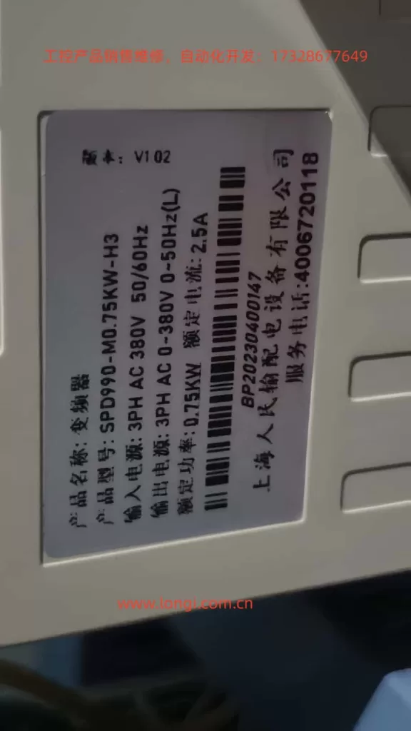
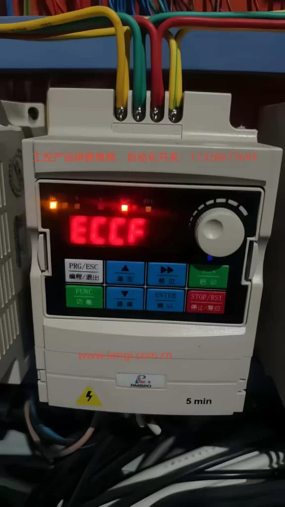
In the field of industrial automation, inverters, as the core equipment for motor drives, directly impact production efficiency and equipment lifespan with their stability. The Shanghai Renmin Electric SPD900M series inverters (e.g., SPD990-M0.75KW-H3) are widely used in loads such as fans, pumps, and conveyor belts due to their high cost-effectiveness and reliability. However, users often encounter the ECCF fault (current detection fault) during operation. If not promptly troubleshot, this fault can lead to inverter shutdown or even damage. This article combines the circuit design and field experience of the SPD900M series to provide an in-depth analysis of the causes, troubleshooting steps, and solutions for the ECCF fault, offering users an operable technical guide.
II. Definition and Classification of ECCF Faults
According to the fault code table of the Shanghai Renmin Electric SPD900M series inverters (see Table 1), the ECCF (current detection fault) falls under the “severe fault” category (fault level 16). Once triggered, the inverter immediately stops outputting and requires fault clearance before resetting. The core logic is that the inverter’s CPU detects abnormal current sampling signals or a failure in the auxiliary power supply that prevents the current detection circuit from functioning properly.
Table 1: SPD900M Series ECCF Fault Classification
| Fault Code | Fault Name | Sub-Fault Type | Fault Description |
|---|---|---|---|
| ECCF | Current Detection Fault | Current Sampling Circuit Fault | Current sampling signal exceeds the normal range (e.g., overcurrent, undercurrent, or signal distortion) |
| Auxiliary Power Supply Fault | Abnormal auxiliary power supply (e.g., 24V/15V) for the current detection circuit, preventing the sampling circuit from functioning |
III. In-Depth Cause Analysis of ECCF Faults
The essence of an ECCF fault is the failure of the current detection chain, involving three links: “auxiliary power supply → sampling circuit → CPU processing.” The following is an analysis of specific causes by link:
(I) Current Sampling Circuit Fault: The Core Cause of Signal Anomalies
The SPD900M series adopts a Hall current sensor + operational amplifier solution for current sampling (some low-power models use sampling resistors). The sampled signal is amplified and filtered before being sent to the CPU’s ADC (analog-to-digital converter). Common fault points include:
1. Sampling Resistor/Sensor Damage
The sampling resistor is a key component for current-to-voltage conversion (e.g., the DC bus sampling resistor is typically 10Ω/5W). If its resistance value changes (e.g., increases from 10Ω to 20Ω) or it becomes open-circuit due to overcurrent, overheating, or aging, the sampled voltage will deviate from the normal value (e.g., the normal sampled voltage is 0-5V, but it may drop below 2V after the change). The CPU detects a “mismatch between the sampled voltage and the actual current” and triggers an ECCF.
Case: A user’s SPD990-M1.5KW inverter frequently reported ECCF. Upon disassembly, it was found that the DC bus sampling resistor was burnt black, and its resistance value had become infinite. After replacing it with a resistor of the same specification, the fault disappeared.
2. Operational Amplifier (Op-Amp) Fault
The sampled signal needs to be amplified by an operational amplifier (e.g., LM358 or TL082). If the op-amp’s gain decreases (e.g., the normal gain is 10 times, but it becomes 5 times after a fault) or its output is offset (e.g., an output of 3V with no input) due to power supply fluctuations, electrostatic discharge, or aging, the signal received by the CPU will be incorrect. For example, after the op-amp is damaged, the sampled signal may be misjudged as “overcurrent” even when the motor current is normal.
3. Poor Contact in Sampling Lines
If the connection terminals of the current sensor (e.g., the “+”, “-“, and “OUT” pins of the Hall sensor) become loose due to vibration or oxidation, the sampled signal may be interrupted or fluctuate. Use a multimeter to measure the continuity of the sampling lines. If the resistance is greater than 1Ω, it indicates poor contact.
4. Electromagnetic Interference (EMI)
If the sampling lines do not use shielded wires or are laid parallel to power lines (e.g., motor cables), they may induce high-frequency noise (e.g., harmonics of the PWM wave), causing distortion of the sampled signal (e.g., superimposing杂波 [jitter or noise] of more than 1V). The CPU cannot recognize the distorted signal and misjudges it as a “current detection fault.”
(II) Auxiliary Power Supply Fault: Failure of the “Power Source” for the Sampling Circuit
The current sampling circuit (e.g., Hall sensors and op-amps) relies on an auxiliary power supply (usually DC24V or DC15V) to function. If the auxiliary power supply is abnormal, the sampling circuit will completely stop working, and the CPU will detect “no sampled signal,” triggering an ECCF. Common causes include:
1. Auxiliary Power Supply Module Damage
The auxiliary power supply of the SPD900M series mostly uses a switching power supply module (e.g., TNY264GN). If the module is damaged due to overvoltage, overcurrent, or poor heat dissipation, the output voltage will be 0V or much lower than the rated value (e.g., 24V drops to 10V). Use a multimeter to measure the output terminal of the power supply module. If the voltage is abnormal, the module needs to be replaced.
2. Filter Capacitor Failure
If the filter capacitors (e.g., electrolytic capacitors 470μF/25V) of the auxiliary power supply bulge or leak due to long-term high temperatures or excessive ripple currents, the power supply ripple will increase (e.g., the ripple voltage increases from 50mV to 500mV), interfering with the normal operation of the sampling circuit. In severe cases, a short-circuited capacitor can cause the power supply module to be overloaded and damaged.
Case: A user’s SPD990-M0.75KW inverter reported ECCF. Upon inspection, it was found that the filter capacitor of the auxiliary power supply was bulging. After replacing the capacitor, the power supply ripple dropped to 80mV, and the fault was eliminated.
3. Short Circuit/Open Circuit in Power Lines
If the input lines of the auxiliary power supply (e.g., the lines from the rectifier bridge to the power supply module) are short-circuited due to damaged insulation, the fuse will blow. If the lines are open-circuited (e.g., loose connection terminals), the power supply module will have no input. Check the continuity and insulation resistance of the lines (use a megohmmeter; it should be greater than 10MΩ).
IV. Systematic Troubleshooting Steps for ECCF Faults
For ECCF faults, it is necessary to follow the principles of “safety first → from simple to complex → verify by link.” The following is the specific troubleshooting process:
Step 1: Safety Operations (Critical!)
The inverter contains high voltages (the DC bus voltage is approximately 540V, and there is still residual charge even after power-off). Before troubleshooting, the following must be done:
- Disconnect the input power supply (R/S/T terminals) of the inverter.
- Wait for more than 5 minutes (to allow the DC bus capacitors to discharge).
- Use a multimeter to measure the DC bus voltage (P/N terminals) and confirm that it is below 36V (safe voltage).
- Wear insulating gloves and avoid touching charged components.
Step 2: Check the Auxiliary Power Supply (Quickly Locate “Power Source” Issues)
The auxiliary power supply is the foundation of the sampling circuit. Checking it first can quickly eliminate common faults:
- Locate the auxiliary power supply module (usually on the left side inside the inverter, marked with “POWER”).
- Use a multimeter to measure the input voltage of the module (AC220V or DC380V, depending on the model).
- Measure the output voltage of the module (e.g., DC24V). If the output voltage deviates from the rated value by more than ±10% (e.g., 24V drops below 20V), it indicates a fault in the power supply module or filter capacitor.
- If the output voltage is normal, continue troubleshooting the sampling circuit.
Step 3: Check the Current Sampling Circuit (Core Link)
If the auxiliary power supply is normal, focus on checking the “signal chain” of the sampling circuit:
1. Check Sampling Resistors/Sensors
- For sampling resistors: Use a multimeter to measure the resistance value (power must be off). If the resistance value deviates from the nominal value by more than ±5% (e.g., a 10Ω resistor becomes 12Ω), it needs to be replaced.
- For Hall sensors: Measure the power supply pins of the sensor (e.g., “+” connected to 24V, “-” connected to GND). If the power supply is normal, measure the voltage of the output pin (“OUT”) (normal is 0-5V, corresponding to the motor current of 0-rated value). If the output voltage is 0V or 5V (saturated), it indicates that the sensor is damaged.
2. Check Operational Amplifiers
- Locate the op-amps in the sampling circuit (e.g., LM358, usually near the sensor).
- Measure the power supply pins (Vcc/GND) of the op-amp to confirm a normal voltage (e.g., 15V).
- Measure the voltages of the input pins (IN+/IN-) and output pin (OUT) of the op-amp: If the input pins have a normal sampled signal (e.g., IN+ is 2V and IN- is 1V), but the output pin has no voltage or an abnormal voltage (e.g., OUT is 0V), it indicates that the op-amp is damaged.
3. Check Sampling Lines
- Use a multimeter to measure the continuity of the sampling lines (e.g., the lines from the sensor to the op-amp). If the resistance is greater than 1Ω, it indicates that the lines are loose or oxidized.
- Check whether the shielding layer of the lines is grounded (the shielding layer needs to be connected to the GND terminal of the inverter, not the chassis). If it is not grounded, reconnect it.
Step 4: Eliminate Electromagnetic Interference (An Often-Overlooked “Invisible Killer”)
If the sampling circuit hardware is normal but the fault still occurs frequently, consider electromagnetic interference:
- Check whether the sampling lines are laid parallel to power lines (e.g., motor cables and input power lines). If so, they need to be laid separately (spacing greater than 20cm).
- Confirm that the shielding layer of the sampling lines is intact (no damage) and reliably grounded (connected to the “GND” terminal of the inverter, not the chassis).
- Use an oscilloscope to measure the waveform of the sampled signal. If there is obvious jitter (e.g., a peak value exceeding 1V) on the waveform, a magnetic ring (e.g., a nickel-zinc magnetic ring) needs to be connected in series in the sampling lines or a filter capacitor (e.g., a 0.1μF ceramic capacitor) needs to be connected in parallel.
Step 5: Verify Whether the Fault is Eliminated
After completing the above troubleshooting and repairs, a “loaded test” is required:
- Power on again and press the “STOP/RST” key to reset the fault.
- Start the motor and observe the display panel of the inverter (whether there is an ECCF alarm).
- Use a clamp-on ammeter to measure the actual current of the motor and compare it with the “output current” displayed by the inverter (the deviation should be less than ±5%).
- If the inverter runs for more than 30 minutes without a fault, it indicates that the troubleshooting is successful.
V. Solutions and Cases for ECCF Faults
(I) Solutions for Common Faults
| Fault Cause | Solution |
|---|---|
| Sampling resistor damage | Replace with a sampling resistor of the same specification (e.g., 10Ω/5W → 10Ω/5W) |
| Operational amplifier damage | Replace with an op-amp of the same model (e.g., LM358 → LM358), and pay attention to the pin definitions (avoid reverse connection) |
| Auxiliary power supply module damage | Replace with a power supply module of the same model (e.g., TNY264GN → TNY264GN), or contact the manufacturer to purchase original parts |
| Filter capacitor failure | Replace with an electrolytic capacitor of the same specification (e.g., 470μF/25V → 470μF/25V, and pay attention to the polarity) |
| Poor contact in sampling lines | Retighten the connection terminals, polish the oxidized layer with sandpaper, or replace with new wires |
| Electromagnetic interference | Add a shielding layer to the sampling lines and ground them, lay them separately from power lines, connect a magnetic ring in series or connect a filter capacitor in parallel |
(II) Typical Case Analysis
Case 1: ECCF Caused by a Burnt Sampling Resistor
- Fault Phenomenon: A SPD990-M1.5KW inverter reported ECCF immediately after startup and could not be reset.
- Troubleshooting Process:
- After power-off and discharge, it was found upon disassembly that the DC bus sampling resistor (10Ω/5W) was burnt black, and its resistance value was infinite.
- Checking the motor cable, it was found that the motor winding was short-circuited (the insulation resistance of the winding measured by a megohmmeter was 0Ω).
- The motor winding (or motor) was replaced, and the sampling resistor was replaced with one of the same specification.
- Result: The inverter returned to normal and no longer reported ECCF.
Case 2: ECCF Caused by Filter Capacitor Failure in the Auxiliary Power Supply
- Fault Phenomenon: A SPD990-M0.75KW inverter frequently reported ECCF, especially in high-temperature environments (summer).
- Troubleshooting Process:
- The output voltage of the auxiliary power supply (DC24V) was normal.
- Using an oscilloscope to measure the power supply ripple, it was found that the ripple voltage was as high as 600mV (normal should be less than 100mV).
- Upon disassembling the power supply module, it was found that the filter capacitor (470μF/25V) was bulging and leaking.
- The filter capacitor was replaced with one of the same specification.
- Result: The power supply ripple dropped to 70mV, the inverter ran stably, and the fault was eliminated.
VI. Preventive Measures for ECCF Faults
To reduce the occurrence of ECCF faults, measures need to be taken from the aspects of “design, use, and maintenance”:
1. Correct Selection and Installation
- Select an appropriate inverter according to the load type (e.g., select “V/F control” for fans and pumps and “vector control” for precision loads).
- Use shielded twisted-pair wires for the sampling lines and reliably ground the shielding layer (connect to the GND terminal of the inverter).
- Lay the power lines separately from the sampling lines (spacing greater than 20cm) and avoid parallel laying.
2. Regular Maintenance
- Clean the dust inside the inverter every 3 months (use compressed air to blow it away) to avoid dust accumulation leading to poor heat dissipation.
- Check the connection terminals (e.g., input and output terminals and sampling line terminals) every 6 months and tighten loose screws.
- Measure the ripple voltage of the auxiliary power supply every year (use an oscilloscope). If the ripple exceeds 100mV, replace the filter capacitor.
3. Reasonable Parameter Settings
- Correctly set the “current detection threshold” (e.g., set the overcurrent protection threshold to 1.2 times the rated current to avoid false alarms).
- Avoid long-term overload operation (the motor current should not exceed 1.1 times the rated current).
- Enable the “current filtering” function (available in some models) to reduce noise in the sampled signal.
4. Manufacturer Service Support
- If the fault cannot be solved by self-troubleshooting (e.g., CPU board damage or sampling circuit design defects), contact the after-sales service of Shanghai Renmin Electric (phone: 4006720118).
- The manufacturer can provide remote diagnosis (through the communication interface of the inverter), on-site maintenance, or part replacement services.
- For models with frequent faults, the manufacturer can upgrade the sampling circuit (e.g., replace with more reliable Hall sensors) to fundamentally solve the problem.
VII. Summary
The ECCF fault is a common fault in the SPD900M series inverters, and its core is the “failure of the current detection chain,” involving multiple links such as the auxiliary power supply, sampling circuit, and electromagnetic interference. During troubleshooting, follow the principles of “safety first and from simple to complex,” first check the auxiliary power supply, then check the sampling circuit, and finally eliminate interference. The solutions should be targeted at specific causes, such as replacing damaged resistors, op-amps, or capacitors, repairing poor line contact, or taking anti-interference measures.
The key to preventing ECCF faults is “regular maintenance + correct use”: regularly clean the dust, check the lines, and measure the power supply ripple; correctly select, install, and set parameters. If a fault that cannot be solved by oneself is encountered, contact the manufacturer in a timely manner to avoid greater losses due to delays.
Through the analysis and guide in this article, it is hoped that users can quickly locate ECCF faults, improve the reliability of inverters, and ensure the continuity of production.