
I. Introduction
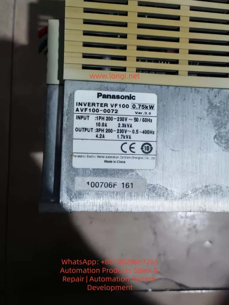
In industrial automation control systems, inverters, as the core equipment for motor driving, directly impact the continuous operation of production lines. The Panasonic VF200 series inverters, known for their compact size, rich features (such as vector control and torque boost), and high reliability, are widely used in load scenarios including fans, pumps, conveyor belts, and packaging machinery. However, in field maintenance, the OP fault (with “OP” displayed on the operation panel) is one of the most common alarms. According to statistics from an auto parts factory, OP faults account for over 35% of all VF200 faults and are often accompanied by motor shutdowns, seriously affecting production efficiency.
This article will comprehensively analyze the OP fault from five dimensions: its definition and manifestations, underlying principles, causes, systematic solutions, and preventive measures. By integrating the Panasonic VF200 technical manual, communication protocol specifications, and field cases, it delves into the root logic of the OP fault, providing maintenance personnel with a practical troubleshooting guide.
II. Definition and Manifestations of the OP Fault
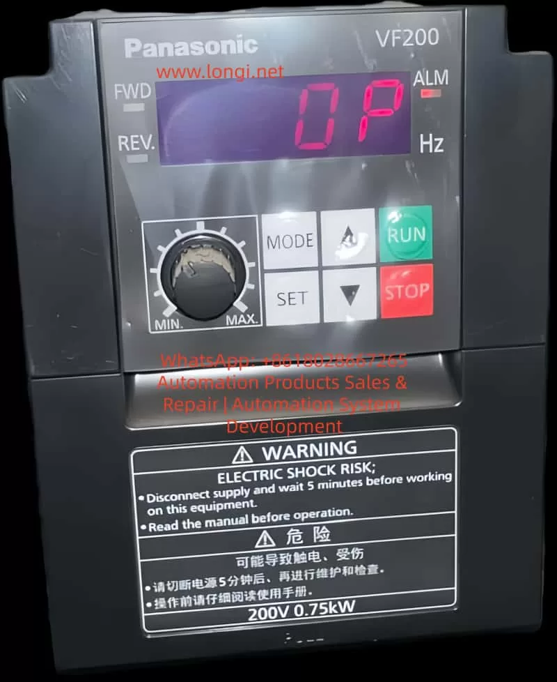
According to the Panasonic VF200 User Manual, the OP fault (Operation Panel Error) is a system-level protection fault triggered by the inverter in response to “communication anomalies between the operation panel and the main body” or “illegal panel states.” The core triggering conditions and manifestations are as follows:
1. Triggering Conditions (Specified in the Manual)
- Power-on during operation: When the inverter is “running” (with FWD/REV signals ON) and the operation panel’s power is suddenly turned on (e.g., by plugging or unplugging the panel cable).
- Communication timeout: The communication signal between the panel and the main body fails to respond within the set time (e.g., no “heartbeat packet” from the panel is received within 1 second).
- Communication cable detachment: The dedicated communication cable between the operation panel and the inverter main body is disconnected.
- Operation panel detachment: The panel is not securely installed (the mechanical lock is loose), or the “installation detection switch” on the panel is disconnected.
2. Fault Manifestations
- The operation panel display shows a fixed “OP” (in red or flashing).
- The ALM alarm light on the inverter is illuminated (on some models).
- The motor stops running (depending on the fault level; OP is a “severe fault” that typically triggers a shutdown by default).
- Parameter setting and start/stop operations cannot be performed via the panel (due to communication interruption).
III. The Essence of the OP Fault: Integrity Protection of the Panel Communication Link
The essence of the OP fault is the inverter’s failure to detect the integrity of the “operation panel-main body” communication link, designed to prevent safety hazards caused by illegal operations or communication interruptions. This can be understood from the following three levels:
1. Hardware Level: Physical Connection Detection of the Communication Link
The VF200’s operation panel is connected to the main body via a dedicated serial communication cable (typically using the RS485 protocol), which includes three groups of lines: power (5V/24V), communication (TXD/RXD), and grounding (GND). The inverter main body continuously monitors the following through hardware circuits (such as optocouplers and voltage detection chips):
- Whether the panel is installed (mechanical switch signal).
- Whether the cable is detached (presence of communication signals).
- Whether the power supply is normal (whether the panel’s supply voltage is within range).
When any of these conditions are not met, the hardware circuit sends an “abnormal signal” to the CPU, triggering the OP fault.
2. Software Level: Timeout Mechanism in the Communication Protocol
The VF200 adopts a Panasonic-specific communication protocol (such as a simplified version of MEWTOCOL-II), where the panel and the main body must regularly exchange “status frames” (e.g., the panel sends its “current display mode,” and the main body replies with “operating parameters”). The protocol sets a timeout threshold (default: 1 second). If no response is received from the other party within this threshold, the CPU determines it as a “communication interruption” and triggers the OP fault.
This mechanism ensures that operators can monitor the inverter’s status in real-time. If communication is interrupted, the panel cannot display operating parameters (such as frequency and current), preventing operators from determining whether the motor is overloaded or abnormal. In such cases, a shutdown is the safest option.
3. System Level: Prevention of Illegal Operations
When the panel’s power is turned on while the “operation signal is ON,” the inverter considers this an illegal operation (as plugging or unplugging the panel during operation may cause communication synchronization failures). Therefore, it triggers the OP fault and forces a shutdown to prevent misoperations (such as parameter modifications that could cause the motor to overspeed).
IV. Causes of the OP Fault: A Full-Link Troubleshooting from Hardware to Software
The causes of the OP fault can be classified into four categories: hardware connection anomalies, incorrect parameter settings, communication interference, and component failures. The following is a detailed analysis:
(I) Hardware Connection Anomalies: The Most Common Field Faults
1. Operation Panel Cable Issues
- Cable detachment/loosening: Field mechanical vibrations (e.g., from machine tools or conveyor belts) may cause the panel cable plug to loosen or the cable to be damaged by collisions. For example, in a packaging machinery application, the VF200 inverter’s panel cable was repeatedly collided by a robotic arm, causing oxidation and poor contact at the plug pins, frequently triggering the OP fault.
- Cable quality issues: Using non-original cables (e.g., homemade cables) or cables with damaged shielding (ungrounded) can lead to signal attenuation in communication. RS485 communication requires a cable with a characteristic impedance of 120Ω. Using ordinary twisted-pair cables (with an impedance of 100Ω) can cause signal reflections and data errors.
- Excessive cable length: The maximum recommended length for the VF200 panel cable is 5 meters (as specified in the manual). If this length is exceeded, signal attenuation can cause timeouts. In a water pump station application, the inverter’s control cabinet was 8 meters away from the panel, and no repeater was installed, leading to communication timeouts and triggering the OP fault.
2. Panel Installation Issues
- Panel detachment: The mechanical lock (or latch) on the panel fails, or the operator does not secure it properly, causing the “installation detection switch” to disconnect. For example, in a textile machinery application, the panel’s latch broke, and it accidentally detached during operation, triggering the OP fault.
- Panel power supply anomalies: The 5V (or 24V) power supply from the inverter main body to the panel fails (e.g., due to a damaged power module or a broken circuit), preventing the panel from functioning and causing communication interruption. Use a multimeter to measure the panel’s power input. If the voltage is below 4.5V (for a 5V specification), check the main body’s power circuit.
(II) Incorrect Parameter Settings: A Hidden Cause Often Overlooked
1. Improper Setting of the Start Mode Parameter P057
P057 is the start mode selection parameter in the VF200 (refer to page 130 of the manual), used to set the allowable state for turning on the panel’s power during operation. Typical setting values are as follows:
| P057 Setting Value | Meaning |
|---|---|
| 0 | Prohibit turning on the panel’s power during operation (default) |
| 1 | Allow turning on the panel’s power during operation |
If the panel needs to be plugged or unplugged during operation (e.g., for panel replacement) but P057 is set to “0” (prohibit), the OP fault will be triggered. For example, in a conveyor belt application, the inverter triggered an OP shutdown when the operator plugged or unplugged the panel during operation because P057 was set to “0.”
2. Excessively Short Communication Timeout Parameter Setting
The communication timeout time in the VF200 is set by parameter P123 (not explicitly specified in the manual; requires viewing via debugging software), with a default value of 1 second. If there is significant interference on-site (e.g., from electric welders or servo drives), the communication signal may experience brief delays (e.g., 1.2 seconds). If P123 is set to 1 second, a timeout may be incorrectly determined, triggering the OP fault.
3. Indirect Impact of the Torque Boost Parameter P007
P007 is the torque boost parameter (refer to page 130 of the manual), used to adjust the output voltage at low speeds (a higher setting value increases low-speed torque). If P007 is set too high (e.g., exceeding 30%), the motor current will increase (especially under light loads), increasing the CPU’s load in the inverter and preventing it from processing communication signals in a timely manner, indirectly causing timeout OP faults. For example, in a fan inverter application, P007 was set to 40%, causing the motor current to consistently exceed the rated value and the CPU load rate to reach 80%. The communication signal processing was delayed, triggering the OP fault.
(III) Communication Interference: A Hidden but Critical Fault Source
1. Electromagnetic Interference (EMI)
High-frequency equipment on-site (such as electric welders, switching power supplies, and servo drives) radiates electromagnetic waves in the range of 100kHz–1GHz, which can couple into the panel cable and distort the communication signal. For example, in an auto factory application, the VF200 inverter experienced OP faults when an electric welder was in operation because the panel cable induced high-frequency interference, causing “glitches” in the communication signal and triggering timeouts.
2. Wiring Interference
- Co-trenching of power and communication lines: When the panel cable is co-trenched with motor and power lines, the high voltage (380V) of the power lines induces common-mode interference, which is superimposed on the communication signal (RS485 differential signals are susceptible to common-mode interference).
- Poor grounding: If the grounding terminals of the inverter main body, panel, and motor are not reliably grounded (grounding resistance > 4Ω), interference signals cannot be discharged, increasing the communication error rate.
(IV) Component Failures: Communication Interruptions Caused by Hardware Damage
1. Operation Panel Failures
- Communication chip damage: The RS485 transceiver (such as MAX485 or SN75176) inside the panel may be damaged by overvoltage (e.g., from static electricity), preventing it from sending or receiving signals. Use an oscilloscope to measure the TXD/RXD pins on the panel. If there is no signal output, the chip is damaged.
- Display module failures: Although display module failures do not directly cause OP faults, they may prevent the panel from displaying “OP.” In such cases, rely on the ALM light (if illuminated, check communication).
2. Inverter Main Body Failures
- Communication interface circuit damage: Aging optocouplers (such as PC817) on the main body can cause signal attenuation (a decrease in the current transfer ratio reduces the signal amplitude), or damage to the RS485 chip (such as MAX485) can prevent it from receiving panel signals.
- CPU communication module failures: Damage to the CPU’s UART (Universal Asynchronous Receiver-Transmitter) interface is rare and is usually accompanied by other faults (e.g., inability to read parameters).
V. Systematic Solution Strategies: A Troubleshooting Process from Simple to Complex
The troubleshooting of OP faults should follow the principle of “hardware first, then software; simple first, then complex.” The following is a standardized process:
Step 1: Quickly Check Hardware Connections (Complete within 10 minutes)
- Check panel installation: Confirm that the panel is securely installed and that the mechanical lock is effective. Press the panel by hand and observe whether the OP disappears (if it does, the installation detection switch has poor contact).
- Check cable connections: Unplug the panel and inspect the cable plug for oxidation or bent pins. Use a multimeter to measure the continuity of TXD-GND and RXD-GND on the cable (normal: conductive). If the cable is broken, replace it with an original cable.
- Check power supply: Use a multimeter to measure the panel’s power input (e.g., 5V supplied by the main body to the panel). If the voltage is abnormal (<4.5V or >5.5V), check the main body’s power module (such as the switching power supply) or the panel’s power circuit.
Step 2: Verify Parameter Settings (A Critical Step)
- Enter parameter mode: Press the “MODE” key on the panel to enter the parameter setting mode (a password is required; default: “0000”).
- Check P057 parameter: Locate P057 (start mode). If it is set to “0” (prohibit turning on the panel’s power during operation) and on-site operations require plugging or unplugging the panel during operation, change it to “1” (allow).
- Check communication timeout parameter: Use debugging software (such as Panasonic FR-Configurator) to view P123 (communication timeout time). If it is set too short (e.g., 0.5 seconds), extend it to 2 seconds (balance response speed and anti-interference capability).
- Restore default parameters: If the parameters are混乱 (chaotic), simultaneously press the “MODE” + “▼” keys to restore the factory settings (note: back up motor parameters, such as P130 motor capacity and P131 motor poles, before restoration).
Step 3: Eliminate Communication Interference (Requires On-site Rectification)
- Environmental rectification: Move the inverter to a location away from interference sources (e.g., inside the control cabinet, >2 meters away from electric welders). Install an EMI filter (such as the Panasonic BFV0015 filter) inside the control cabinet to suppress power-side interference.
- Wiring rectification:
- Separate the panel cable from power lines (motor and power lines) by at least 10cm and avoid co-trenching.
- Use shielded cables (shield both ends grounded, grounding resistance < 4Ω).
- Install ferrite cores on the panel cable (wind 2–3 turns) to suppress high-frequency interference (the core’s impedance should match the interference frequency, e.g., a 100MHz core for suppressing high-frequency interference).
- Grounding optimization: Ensure that the grounding terminals of the inverter main body, panel, and motor are reliably grounded (use copper wires of at least 2.5mm² for grounding and bury the grounding electrode 1.5 meters underground). Connect the grounding bar inside the control cabinet to the factory’s grounding system.
Step 4: Component Replacement and Advanced Diagnostics (For Stubborn Faults)
- Replace the operation panel: Use a spare panel of the same model to replace the original panel. If the OP disappears, the original panel is faulty (requires repair or replacement). If the OP persists, the main body is faulty.
- Test the main body’s communication interface: Use an oscilloscope to measure the TXD/RXD signals at the main body’s communication interface (RS485 differential signals; the voltage difference between A and B should be ≥200mV). If the signal amplitude is too low (<100mV), the optocoupler or RS485 chip is damaged, and the main board needs to be replaced.
- Use debugging software: Use FR-Configurator software to read the fault records (e.g., the trigger time of the OP fault, the operating frequency, and current at that time) and analyze the fault patterns (e.g., whether it is triggered during electric welder operation or when the panel is plugged or unplugged during operation).
VI. Field Case Analysis: Typical Scenarios and Solutions for OP Faults
Case 1: OP Fault Caused by Cable Loosening
- Scenario: A VF200 inverter (0.75kW) on packaging machinery suddenly displayed OP during operation, and the motor stopped.
- Troubleshooting: The panel cable was inspected, and oxidation and poor contact were found at the plug pins. After re-plugging and cleaning the pins, the OP disappeared.
- Cause: Mechanical vibrations caused the cable to loosen, leading to communication interruption and triggering the OP fault.
- Solution: Replace the cable with an original one featuring a lock to prevent future loosening.
Case 2: Timeout OP Fault Caused by Interference
- Scenario: A VF200 inverter at a water pump station frequently displayed OP during electric welder operation, causing the motor to shut down.
- Troubleshooting: The wiring was inspected, and the panel cable was found to be co-trenched with the electric welder’s power line. Using an oscilloscope, high-frequency glitches (amplitude: 1V) were detected in the communication signal. After installing ferrite cores and an EMI filter, the OP disappeared.
- Cause: High-frequency interference from the electric welder coupled into the communication cable, causing timeouts.
- Solution: Separate the wiring and install interference suppression devices.
Case 3: OP Fault Caused by Incorrect P057 Setting
- Scenario: A VF200 inverter on a conveyor belt triggered an OP shutdown when the operator plugged or unplugged the panel during operation.
- Troubleshooting: The P057 parameter was checked and found to be set to “0” (prohibit turning on the panel’s power during operation). After changing it to “1,” plugging or unplugging the panel during operation no longer triggered the OP fault.
- Cause: Incorrect P057 setting prohibited panel operations during operation.
- Solution: Adjust the P057 parameter according to on-site requirements.
VII. Preventive Measures: Reducing OP Faults from the Source
- Regular maintenance: Inspect the panel cable (plug, pins) and grounding every quarter. Clean the panel dust (to prevent contact issues due to dust) and check the effectiveness of the mechanical lock.
- Parameter backup: Regularly back up the inverter parameters (such as motor parameters and P057 settings) using FR-Configurator software to prevent parameter loss or incorrect modifications.
- Environmental optimization: Install the inverter in a well-ventilated, interference-free control cabinet (temperature: -10–50°C, humidity: <80%). Install fans or air conditioners inside the control cabinet to prevent component aging due to high temperatures.
- Operator training: Train operators on the correct installation and removal of the panel (avoid colliding with the cable) and inform them of the meaning of the OP fault (panel communication anomaly). In case of a fault, do not force operations and contact maintenance personnel promptly.
- Spare parts management: Stock common spare parts (such as operation panels, communication cables, and EMI filters) to shorten fault downtime (the average downtime for an OP fault is about 30 minutes; with sufficient spare parts, it can be reduced to 10 minutes).
VIII. Conclusion
The OP fault in the Panasonic VF200 inverter is a concentrated manifestation of anomalies in the “panel-main body” communication link, representing the inverter’s safety protection mechanism at its core. Resolving OP faults requires a systematic troubleshooting approach: from hardware connections (cables, panels) to parameter settings (P057, timeout parameters), then to interference suppression (wiring, grounding), and finally to component replacement (panels, main bodies).
Maintenance personnel should familiarize themselves with the VF200’s communication protocol (such as MEWTOCOL), parameter functions (such as P057, P007), and hardware structure (such as communication interface circuits) and quickly locate faults by referring to field cases. Through regular maintenance and preventive measures, the incidence of OP faults can be reduced by over 70%, significantly improving the inverter’s reliability.
In the era of Industry 4.0, while inverters are becoming increasingly intelligent, the stability of the basic communication link remains the core of reliable equipment operation. The troubleshooting process for OP faults essentially involves sorting out the interaction between “equipment-humans-environment.” Only by understanding the underlying logic of faults can we shift from “passive maintenance” to “active prevention” and truly achieve full-lifecycle management of equipment.