
1. Background and Practical Significance
Yaskawa Σ-II series (SGDM) servo drives are widely used in industrial automation systems such as CNC machines, packaging equipment, printing lines, and conveyor systems. As equipment ages, alarm-related failures become increasingly common in maintenance work.
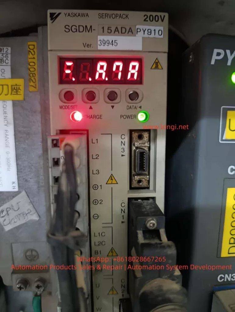
Among these, Alarm A.7A (Heatsink Overheat) is a frequent issue and is often misdiagnosed in the field.
Many engineers treat A.7A purely as a thermal problem—focusing on cooling improvements or fan replacement. However, real-world repair experience shows:
A.7A does not always indicate actual overheating—it indicates that the drive believes it is overheating.
Understanding the detection mechanism and signal chain is therefore essential for accurate troubleshooting.
2. Official Definition and Technical Essence of A.7A
According to the Yaskawa SGDM manual:
- A.7A indicates a heatsink overheat alarm
- It is triggered when the drive detects that the heatsink temperature exceeds a defined threshold
However, from a circuit perspective, the system does not directly measure temperature. Instead, it relies on voltage interpretation:
Temperature → Resistance change → Voltage change → CPU decision
Thus, A.7A is fundamentally a fault or anomaly in an analog sensing circuit, not just a thermal condition.
3. Temperature Detection Circuit Principle
The SGDM servo drive uses an NTC (Negative Temperature Coefficient) thermistor-based sensing circuit. The structure typically includes:
- NTC thermistor (mounted on the heatsink)
- Pull-up resistor (connected to a 5V reference)
- Operational amplifier (signal conditioning)
- CPU ADC (analog-to-digital conversion)
Working principle:
- NTC resistance decreases as temperature increases
- Together with the pull-up resistor, it forms a voltage divider
- The divider outputs a voltage signal (Vtemp) proportional to temperature
- The signal is conditioned by an op-amp
- The CPU compares the voltage against a threshold
Typical voltage behavior:
- Normal temperature: ~2V to 3V
- Rising temperature: voltage decreases
- Below ~1V: triggers A.7A alarm
4. Fault Classification of A.7A
From a maintenance standpoint, A.7A can be divided into two major categories:
4.1 Real Overheating (Physical Cause)
Common causes include:
- Ambient temperature exceeding 55°C
- Blocked airflow (dust accumulation or tight installation)
- Cooling fan failure or reduced speed
- Prolonged overload operation
- Excessive IGBT heat generation
Typical characteristics:
- Alarm occurs after a period of operation
- Heatsink temperature is physically high
4.2 False Alarm (Circuit-Level Issue)
This is more critical from a repair perspective. Common causes include:
- NTC thermistor open circuit or short circuit
- Drifted pull-up resistor
- Faulty operational amplifier (offset or saturation)
- ADC sampling error
- Poor solder joints or connector issues
Typical characteristics:
- Alarm appears immediately after power-on
- Heatsink temperature is normal or low
5. Board-Level Troubleshooting Using a Multimeter
5.1 NTC Thermistor Check
Measure resistance with power OFF:
- Normal: several kΩ to tens of kΩ
- Open circuit: infinite resistance (will trigger alarm)
- Short circuit: near 0Ω (abnormal)
Further verification:
- Apply heat (e.g., hot air)
- Resistance should decrease accordingly
5.2 Voltage Divider Node Measurement (Critical)
Measure the voltage at the junction between the NTC and pull-up resistor (Vtemp):
- Normal: 2V–3V
- 0V: NTC short or grounding issue
- 5V: NTC open or pull-up fault
- <1V: interpreted as overheat
This point is the most important diagnostic node.
5.3 Pull-Up Resistor Check
Measure resistance with power OFF:
- Typical range: 4.7kΩ to 47kΩ
- Open or drifted values will cause incorrect voltage levels
5.4 Operational Amplifier Check
Identify the op-amp (commonly an 8-pin IC such as LM358):
- Input pins: should match Vtemp level
- Output pin: should vary within 0–5V range
Failure symptoms:
- Output stuck high: false alarm
- Output stuck low: continuous alarm
- No response: op-amp failure
Op-amp drift is a common issue in aging SGDM drives.
5.5 Substitution Method (Fast Diagnosis)
Remove the NTC and replace it with fixed resistors:
- 10kΩ → simulate normal temperature
- 1kΩ → simulate high temperature
- 500Ω → simulate extreme heat
Interpretation:
- Alarm disappears → NTC is faulty
- Alarm persists → downstream circuit issue
6. Recommended Troubleshooting Workflow
A structured approach significantly improves efficiency:
- Determine when the alarm occurs
- Immediate → circuit issue
- After running → thermal issue
- Check cooling fan
- Rotation and supply voltage
- Measure NTC resistance
- Measure Vtemp voltage
- Check op-amp input/output
- Perform substitution test
This process typically allows fault localization within 10–15 minutes.
7. Failure Probability Distribution (Based on Field Experience)
- Cooling fan failure: very high
- Poor ventilation/dust: high
- NTC failure or poor connection: medium-high
- Op-amp drift: medium
- Resistor drift: medium-low
- CPU/ADC fault: low
8. Common Misdiagnoses
- Treating A.7A purely as a temperature issue
- Focusing only on cooling improvements
- Ignoring the analog sensing circuit
- Failing to distinguish real vs false alarms
These mistakes often lead to unnecessary part replacement or repeated failures.
9. Conclusion
The A.7A alarm is not simply a thermal issue but a signal chain evaluation problem. Its core characteristics are:
- Temperature is inferred through analog voltage
- Any fault in the sensing chain can trigger the alarm
Therefore, the key to effective repair is not just reducing temperature, but:
Precisely identifying faults within the temperature sensing circuit
By understanding the NTC-based voltage divider, measuring the critical Vtemp node, and applying substitution testing, engineers can efficiently diagnose and repair SGDM servo drives at the board level—significantly reducing downtime and maintenance costs.