
Abstract: In the field of industrial automation, the ABB ACS800 series inverter is renowned for its high power density, parallel inverter module design, and Direct Torque Control (DTC) technology, widely used in high-power applications such as metallurgy, cranes, papermaking, and water pumps. However, when the system displays an “INT CONFIG (5410)” fault accompanied by an AC contactor that fails to latch and a DC link voltage stuck at 347.9 V (significantly lower than the normal ~540 V), it often indicates a deep-seated issue in the pre-charge circuit or module communication link. Based on actual cases, ABB official fault manuals, hardware schematics, and on-site troubleshooting experience, this article provides a comprehensive technical analysis of the fault and offers a full-link solution—from phenomenon identification to root cause elimination and preventive maintenance—helping engineers quickly restore equipment operation and avoid secondary failures.
I. Overview of ACS800 Parallel Inverter Architecture: Why Configuration Faults Are Critical
The ACS800 (especially cabinet-type multi-drive or CraneDrive versions) adopts a modular parallel design. High-power models (such as the R8i series) achieve current sharing through parallel connection of multiple inverter units. Core control is managed by the APBU (PPCS Branching Unit) board, which communicates with each module via fiber optics (PPCC LINK) to achieve synchronized PWM and status monitoring.
Normal Power-Up Sequence
- Main line contactor closes.
- Pre-charge Circuit slowly charges the DC link capacitors through a current-limiting resistor.
- Pre-charge Bypass Contactor engages, shorting the resistor, and the DC link voltage rises to the rated value (for a 400 V system, typical UDC=1.35×400V≈540V).
- Inverter modules power up, and the APBU detects the number of modules and compares it with parameter
95.03 INT CONFIG USER. - If consistent: Drive is Ready; Otherwise: INT CONFIG (5410) is triggered.
Key Logic: When pre-charging fails, the DC link voltage only reaches 347.9 V (approx. 64% of rated value). Some modules fail to initialize properly, causing the APBU to misjudge “module count mismatch” and directly trigger fault 5410. This is not an isolated communication issue but a chain reaction of hardware power-up chain interruption.
Parallel systems have extremely high requirements for configuration consistency: even a missing module can cause IGBT overload or output imbalance due to uneven current distribution. Parameter 95.03 defaults to the factory module count (e.g., 2 or 4); any physical loss or insufficient voltage triggers protection.
II. Precise Interpretation of Fault Phenomena: Meaning of “347.9 V + INT CONFIG 16 (5410)”
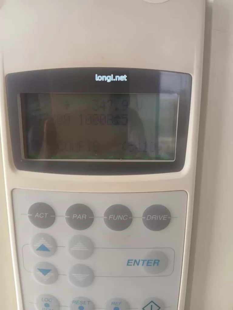
The panel photo provided by the user shows:
- Top:
347.9 V(Real-time DC link voltage, far below normal). - Middle:
U 32000 10008±5(Likely an internal signal or configuration word). - Bottom:
INT CONFIG 16 (5410).
Phenomenon Analysis
- Meaning of “16”: Likely corresponds to the internal configuration word (
08.22 INT CONFIG WORD) or extended fault info, indicating 1 abnormal module detected (or total module mismatch). Press the ACT key to view04.01 FAULTED INT INFOto precisely identify the faulty module number (INT 1~N). - “AC Contactor Not Hold”: This is the core symptom, referring to the main line contactor or pre-charge bypass contactor coil failing to latch (insufficient coil voltage, mechanical jamming, or auxiliary contact self-holding failure).
- Reason for Voltage Lock: Contactor chatter or instant engagement followed by drop-out → Pre-charge resistor cannot be shorted → Bus voltage stays at the low value after voltage division by the resistor (347.9 V is the typical “semi-charged” state limited by the pre-charge resistor).
Why is the voltage stuck?
- Resistor Charging Stage: UDC slowly climbs to ~410 V (UDC,chr charging threshold).
- After Bypass Contactor Closes: Resistor is shorted, UDC rapidly rises to 540 V.
- Fault State: Contactor not holding → Resistor remains in circuit → Voltage cannot reach full charge → Module undervoltage → Configuration failure.
III. In-Depth Root Cause Analysis: The Link Between Pre-Charge Circuit, Contactor, and INT CONFIG
3.1 Typical Composition and Failure Modes of Pre-Charge Circuit
The pre-charge circuit for high-power ACS800 models includes: charging resistors (e.g., 3.3 Ω / 65 W, multiple in parallel), a bypass contactor (or thyristor), a half-wave rectifier diode (prevents reverse flow), and voltage detection/timing logic (controlled by AINP/AIBP boards).
Failure Mode Ranking (High to Low Probability):
- Bypass Contactor Failure (Most Common): Coil burnout, contact erosion, unstable control power (220 V / 110 V / 24 VDC), oxidized auxiliary contacts. Result: Resistor cannot be shorted, leading to continuous heating or burnout.
- Pre-Charge Resistor Open/Drift: Carbonization after long-term energization or multiple cycles, increased resistance, too small charging current.
- Diode or Thyristor Breakdown/Open: Causes asymmetric charging path.
- Control Board Issues: Low output from APOW power board, abnormal detection circuit on AINT board.
3.2 Electrical and Mechanical Reasons for AC Contactor Not Holding
- Control Circuit: Contactor coil voltage below 85% of rated value (measure voltage at coil terminals), excessive series resistance, relay outputs (RO1/RO2) locked by fault.
- Mechanical Factors: Iron core jamming, spring fatigue, contact welding.
- Power Supply Factors: High ripple in auxiliary control power (24 V or 110 V), poor grounding.
- Drive Interlock: The INT CONFIG fault itself locks the contactor output, further worsening the cycle.
3.3 Impact of Low Voltage on Parallel Modules
When DC link voltage is below UDC,uvc (undervoltage control threshold ≈ 436 V), modules cannot complete self-check. The status word read by APBU via fiber optics is “Not Ready”. Even if fiber optics are intact, insufficient voltage is judged as “module missing,” triggering 5410. Bit 10 of parameter 03.17 FAULT WORD 5 will be set to 1.
IV. On-Site Diagnostic Procedure: Step-by-Step Positioning, Confirm Root Cause in 30 Minutes
⚠️ Safety First: Power off, lockout/tagout, discharge capacitors (wait >5 min, confirm <50 V with multimeter).
1. Panel Data Collection (No Dismantling Required)
ACT→01.02 DC BUS VOLTAGE(Confirm 347.9 V).ACT→04.01 FAULTED INT INFO(Record faulty module).PAR→95.03 INT CONFIG USER(Check current setting).ACT→08.22 INT CONFIG WORD(Status bits of each module).
2. Hardware Inspection of Contactor & Pre-Charge (Highest Priority)
- Visual: Check for burnt smell on contactor, blackened contacts, or carbonized resistor surface.
- Power-on Test: Measure contactor coil voltage (should be ≥ 85% rated).
- Manual Bypass Test (Emergency): After power-off, short bypass contactor main contacts with insulated tool. Power on and observe if voltage rises to 540 V. If it rises, contactor failure is confirmed.
- Resistance Measurement: Measure resistor value after power-off (should match nameplate, deviation < 10%).
3. Fiber Optic & Module Communication Link (If voltage is normal but fault persists)
- Check fiber optics from APBU to modules: Clean end-faces, no bending, fully inserted.
- Swap fiber positions to see if the fault follows the movement.
4. Power Supply & Auxiliary Circuits
- Measure control power stability.
- Check self-holding circuit of main line contactor auxiliary contacts.
V. Repair Solutions: Hardware First, Parameters Second, Balancing Emergency and Permanent Fixes
5.1 Immediate Repair
- Replace Contactor: Prioritize original or equivalent models, ensure coil voltage matches.
- Replace Pre-Charge Resistor: Replace the whole set, avoid single repair.
- Clean Fiber Optics: Wipe end-faces with alcohol cotton.
- Temporary Bypass Shorting (Debugging only): Confirm voltage is normal then restore immediately; strictly prohibited for long-term operation.
5.2 Parameter Adjustment (Reduced Run Mode)
- Enter
PARmenu, modify95.03 INT CONFIG USERto the actual number of available modules (e.g., change from 2 to 1). - Save → Power cycle → RESET.
- Also check
95.10Ambient Temp setting and cooling fans.
5.3 Advanced Verification
- Monitor
01.02voltage rise curve after power-up (should reach target in < 5 s). - Run light load, observe if
03.19 INT INIT FAULTclears. - Record fault history (
03.20 LATEST FAULT).
VI. Preventive Maintenance & Best Practices: Avoid Recurrence
- Regular Inspection: Check pre-charge resistor temperature, contactor contact wear, and fiber cleanliness every 6 months.
- Parameter Backup: Export full parameters (via DriveStudio or panel) after commissioning.
- Environmental Control: Cabinet temp < 40°C, clean dust filters, add voltage regulator to control power.
- Spare Parts Strategy: Keep 1 set of pre-charge resistors + main contactor for high-power models.
- Software Monitoring: PLC reads DC BUS VOLTAGE and FAULT WORD via fieldbus, set warning threshold (< 500 V alarm).
- Upgrade Suggestion: Consider migrating old models to ACS880, which has a more reliable pre-charge circuit.
VII. Real Case Review: Complete Solution Path for Indian Customer Machine
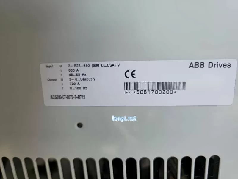
Case Background: An ACS800 cabinet (2 parallel R8i modules, 400 V system) at an Indian factory showed the described symptoms. Panel showed 347.9 V + INT CONFIG 5410, contactor chattering.
Findings:
- Oxidized auxiliary contacts on pre-charge bypass contactor.
- Resistor value drifted from 3.3 Ω to 12 Ω.
- Failure to fully charge caused 1 module to be unrecognized.
Process:
Replaced contactor + resistor bank → Temporary shorting verified voltage rose to 548 V → Updated 95.03 to 1 → RESET cleared fault.
Result: No recurrence after 3 months of operation.
Conclusion: This case proves that for >90% of INT CONFIG faults accompanied by low voltage, the root cause is pre-charge hardware, not fiber optics or software.
VIII. Conclusion & Extended Thinking
The INT CONFIG (5410) fault on ABB ACS800 is not merely a “configuration error” but a systemic protection signal fed back from DC link charging failure. AC Contactor Not Hold and 347.9 V Low Voltage are two manifestations of the same issue. By focusing on the critical node of the pre-charge circuit, the problem can be solved efficiently.
Troubleshooting Principle for Engineers:
Voltage First, Hardware Second, Parameters Third
Avoid blindly modifying parameters to mask hidden dangers. Hardware circuit faults must be thoroughly eliminated to prevent module explosions or main circuit short circuits.