
Abstract
This paper delves into the multifaceted impacts of motor dust accumulation on the operation of KECEN inverters (KC480/KC500 series) from Chuan Science, focusing particularly on Err10 (Drive Overload) and a hypothetical Err1 (Drive Unit Protection) fault. Through a systematic analysis of how dust affects motor heat dissipation, insulation performance, mechanical components, and electrical connections, comprehensive and targeted solutions are proposed. This paper aims to provide industrial field technicians with a detailed and practical guide for fault handling and prevention, ensuring the long-term stable operation of motors and inverters.
1. Introduction
In the field of industrial automation, inverters serve as the core equipment for motor speed control, and their stable operation is crucial for ensuring the continuity and efficiency of production lines. However, motors and inverters often face various challenges in practical operation, among which motor dust accumulation is a prevalent yet easily overlooked issue. This paper will take KECEN inverters (KC480/KC500 series) as an example to analyze in detail how motor dust accumulation can lead to Err10 (Drive Overload) and a hypothetical Err1 (Drive Unit Protection) fault, and propose corresponding handling and preventive measures.
2. Fault Overview
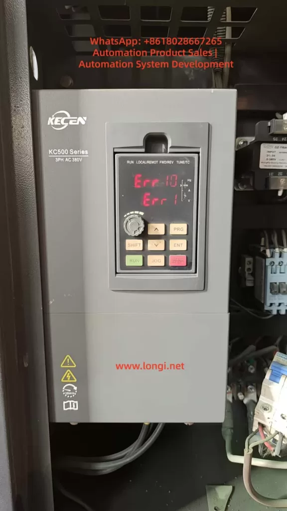
2.1 Err10 Fault: Drive Overload
The Err10 fault typically indicates drive overload in KECEN inverters, meaning the motor load exceeds the rated carrying capacity of the inverter. This fault can be triggered by various factors, including excessive load, motor lock-up, inadequate inverter power rating, or improper setting of motor overload protection parameters. However, motor dust accumulation, as an indirect yet significant factor, should not be overlooked.
2.2 Hypothetical Err1 Fault: Drive Unit Protection
The Err1 fault is hypothesized here as drive unit protection, which may involve abnormalities in the inverter’s internal power module, drive circuit, or control board. Although the specific fault code and表现形式 (manifestations) may vary by manufacturer, drive unit protection is typically closely related to abnormal conditions such as overcurrent, overvoltage, and overheating. Motor dust accumulation may indirectly trigger such protection mechanisms by affecting heat dissipation or causing poor electrical connections.
3. Multidimensional Impacts of Motor Dust Accumulation
3.1 Poor Heat Dissipation
Mechanism of Impact: Motors generate significant heat during operation, which must be effectively dissipated through heat sinks and fans. Dust accumulation can cover the heat sinks, obstructing heat dissipation and leading to a continuous rise in motor temperature.
Impact on Inverter: Motor overheating can trigger the inverter’s overload protection (Err10). Additionally, long-term high-temperature operation can accelerate the aging of internal components in the inverter, increasing the risk of faults.
3.2 Degraded Insulation Performance
Mechanism of Impact: Dust may contain conductive substances, such as metal particles and carbon powder. Accumulation of these substances on motor windings and insulation materials can degrade insulation performance. In humid environments, this situation can be particularly severe, potentially leading to internal short circuits in the motor.
Impact on Inverter: Internal short circuits in the motor can trigger the inverter’s overcurrent protection or drive unit protection (hypothetical Err1) and even damage internal components of the inverter.
3.3 Increased Mechanical Wear
Mechanism of Impact: Once dust enters the motor, it can cause wear on mechanical components such as bearings and gears. Long-term accumulation can lead to unstable motor operation, producing vibrations and noise.
Impact on Inverter: Increased mechanical wear-induced motor load can trigger the inverter’s overload protection (Err10). Additionally, vibrations and noise may also affect the normal operation and lifespan of the inverter.
3.4 Poor Electrical Connections
Mechanism of Impact: Dust accumulation on electrical connection points can lead to poor contact, increasing contact resistance and generating additional heat. This can result in voltage drops, current imbalances, and even open circuits.
Impact on Inverter: Poor electrical connections can trigger various protection mechanisms in the inverter, including overcurrent protection and drive unit protection (hypothetical Err1), and may also cause damage to internal components.
4. Handling and Preventive Measures
4.1 Cleaning Motor Dust
Operational Steps:
- Preparation: Gather appropriate cleaning tools, such as compressed air, vacuum cleaners, soft brushes, and cleaning cloths.
- Shutdown and Disconnection: Ensure the motor and inverter are completely shut down and disconnected from the power supply before cleaning.
- External Cleaning: Use a vacuum cleaner or soft brush to remove dust from the motor’s exterior, including heat sinks, fans, and ventilation openings.
- Internal Cleaning (if accessible): For motors with accessible interiors, use compressed air to blow out dust from windings, bearings, and other components. Exercise caution to avoid damaging delicate parts.
- Final Inspection: After cleaning, visually inspect the motor for any signs of damage or wear. Reassemble any disassembled parts and ensure all connections are secure.
4.2 Inspecting and Optimizing the Heat Dissipation System
Operational Steps:
- Visual Inspection: Check for any obstructions or damage to heat sinks, fans, and ventilation openings.
- Fan Operation Test: Manually rotate the fan blades to ensure they move freely without obstruction. Power on the motor (if safe to do so) and verify that the fan operates correctly.
- Cleaning Heat Sinks: Use a soft brush or compressed air to remove dust from heat sinks, ensuring optimal heat transfer.
- Thermal Paste Application (if necessary): If the motor has been disassembled, apply a thin layer of thermal paste between the motor and heat sink to enhance heat conduction.
4.3 Calibrating and Optimizing Inverter Parameters
Operational Steps:
- Overload Protection Parameters: Set the inverter’s overload protection parameters reasonably based on the motor’s actual load conditions to avoid false triggering.
- Acceleration and Deceleration Times: Adjust acceleration and deceleration times according to motor and load characteristics to reduce inrush currents during startup and stopping.
- V/F Curve Adjustment: Optimize the V/F curve settings based on motor load characteristics to improve motor operating efficiency and stability.
4.4 Strengthening Routine Maintenance and Monitoring
Operational Steps:
- Regular Cleaning: Establish a regular cleaning schedule for motors and inverters to ensure equipment cleanliness.
- Condition Monitoring: Regularly check the operating status of motors and inverters, including temperature, vibration, and noise levels, to detect and address anomalies promptly.
- Parameter Recording: Record inverter parameter settings and operating data to facilitate fault analysis and parameter optimization.
4.5 Environmental Improvement and Protection
Operational Steps:
- Dust Prevention Measures: Install dust covers or take other dust prevention measures around motors and inverters to reduce dust ingress.
- Regular Cleaning of Work Area: Regularly clean the work area to maintain a clean environment and reduce dust concentration.
- Humidity Control: In humid environments, take dehumidification measures to prevent dust and moisture from combining and degrading insulation performance.
5. Case Study
5.1 Case Background
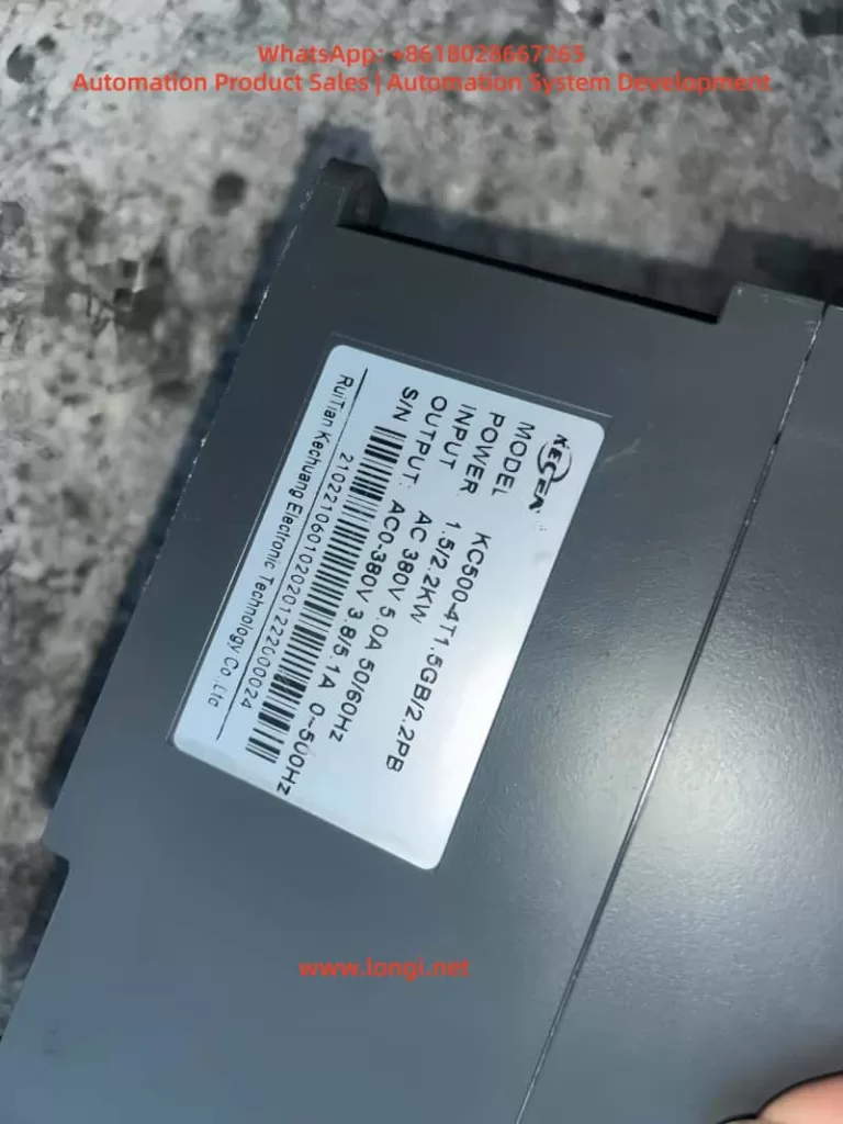
A factory’s production line experienced frequent Err10 (Drive Overload) and hypothetical Err1 (Drive Unit Protection) faults with its KECEN inverter (KC500 series), leading to multiple production line shutdowns. Technicians initially suspected motor overload but found that the motor load did not exceed the rated value upon inspection.
5.2 Fault Investigation
Further investigation revealed significant dust accumulation inside the motor, with heat sinks covered in dust, leading to poor heat dissipation. Additionally, poor electrical connections due to dust accumulation were also observed.
5.3 Handling Measures
- Cleaning Motor Dust: Thoroughly cleaned the motor’s interior using compressed air and vacuum equipment.
- Inspecting Heat Dissipation System: Confirmed that the cooling fan and heat sinks were functioning properly without blockages or damage.
- Securing Electrical Connections: Checked and tightened all electrical connection points to ensure good contact.
- Calibrating Inverter Parameters: Reasonably set overload protection parameters and other key parameters based on the motor’s actual load conditions.
- Strengthening Routine Maintenance: Established a regular cleaning schedule for motors and inverters and enhanced condition monitoring and parameter recording.
- Environmental Improvement: Added dust covers around motors and inverters and regularly cleaned the work area.
5.4 Handling Results
After implementing the above handling measures, the inverter no longer experienced Err10 or hypothetical Err1 faults, and the production line resumed stable operation.
6. Conclusion
Motor dust accumulation is a significant factor contributing to inverter Err10 (Drive Overload) and hypothetical Err1 (Drive Unit Protection) faults. By implementing comprehensive measures such as cleaning motor dust, inspecting and optimizing the heat dissipation system, calibrating and optimizing inverter parameters, strengthening routine maintenance and monitoring, and improving the environment, these issues can be effectively resolved, and similar faults can be prevented from recurring. Industrial field technicians should fully recognize the hazards of motor dust accumulation and take effective measures to prevent and handle it, ensuring the long-term stable operation of motors and inverters.