
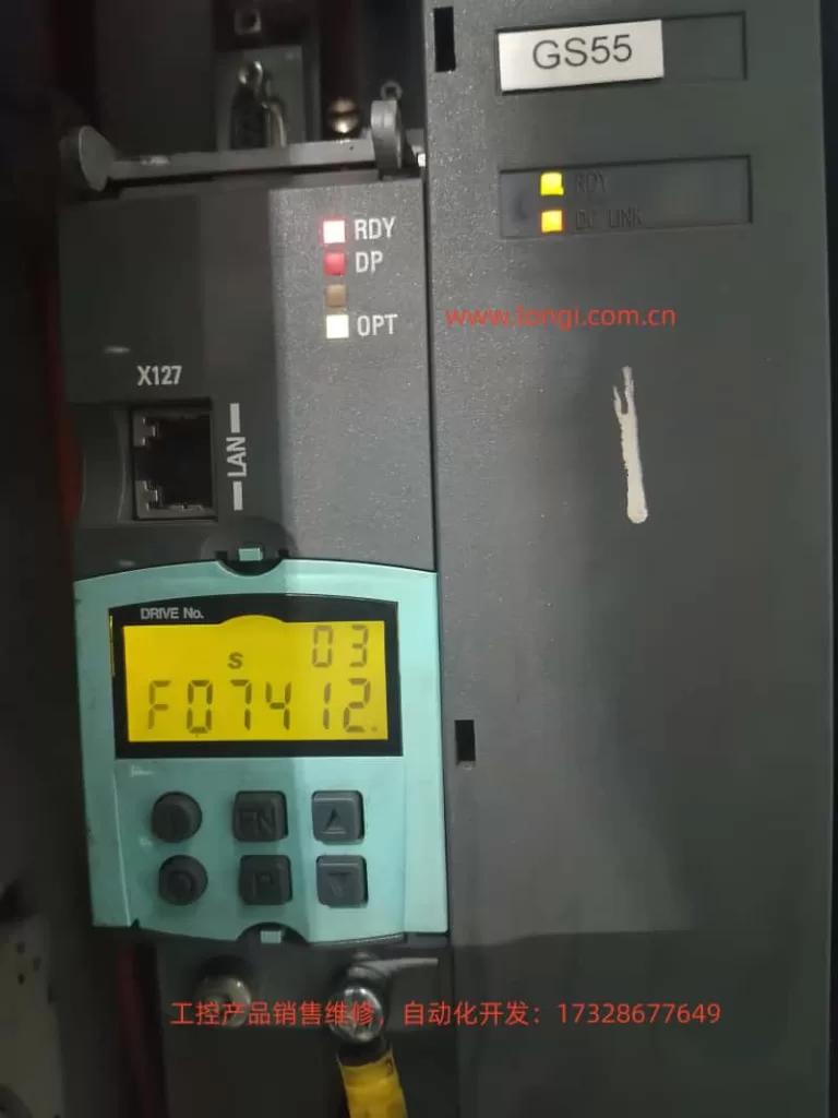
The SINAMICS S120 is Siemens’ modular high-performance servo drive system, widely used in CNC machine tools, robotics, packaging machinery, and precision servo applications. Its CU320-2 control unit, combined with Motor Modules and DRIVE-CLiQ encoders, forms a multi-axis synchronous control architecture. When the BOP panel displays “F074 12.”, the F07412 fault is triggered. This fault directly points to a deviation between the commutation angle and the motor model calculation, potentially causing positive feedback in the speed controller, system oscillation, or even hardware damage. This article provides a systematic expansion from system architecture and fault mechanism to parameter interpretation, diagnostic procedures, exclusion steps, and prevention strategies, offering a directly actionable engineering guide.
SINAMICS S120 System Architecture and Commutation Control Fundamentals
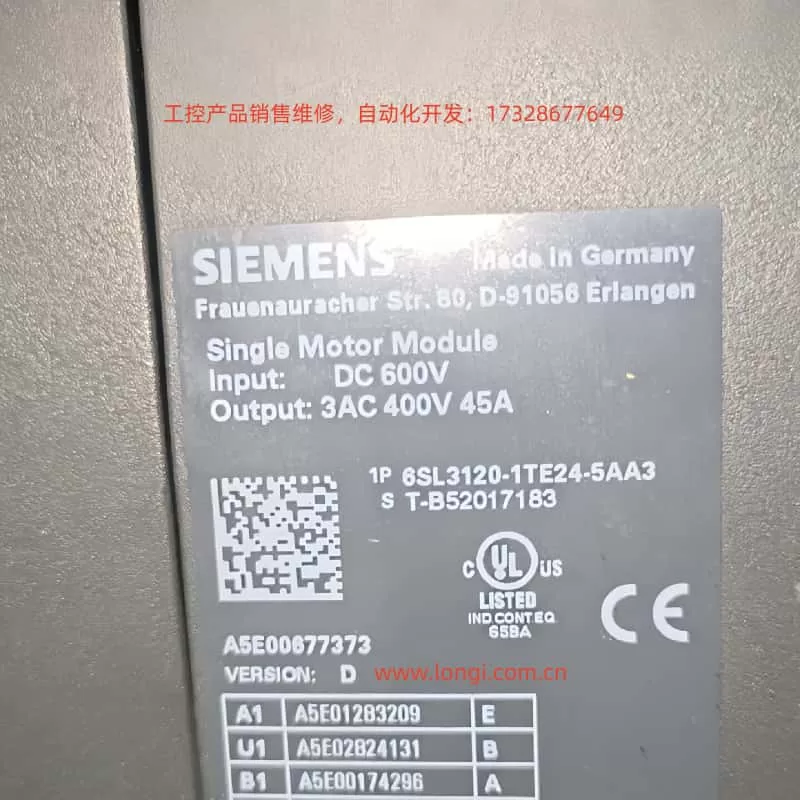
The SINAMICS S120 adopts a Booksize/Chassis modular design. The core is the CU320-2 Control Unit (supporting PROFIBUS/PROFINET, X127 Ethernet debugging port). The power supply side uses an Active Line Module or Smart Line Module, with a DC bus voltage of 510-720V; the drive side uses Motor Modules (single-axis/dual-axis), connected to SMC/SME Sensor Modules and motor encoders via a DRIVE-CLiQ ring topology.
For Permanent Magnet Synchronous Motors (PMSM, p0300=2xx), commutation control is critical. The drive needs to obtain the rotor pole position θe (electrical angle) in real-time and convert the three-phase current into the dq coordinate system via Park transformation:
id=I⋅cos(θe−α)
iq=I⋅sin(θe−α)
Where α is the commutation angle (p0431 offset). If the deviation of α exceeds the threshold (SERVO >80° elec, VECTOR >45° elec), the iq torque component creates positive feedback, the speed loop gain sign reverses, leading to unstable oscillations. The motor model (based on the equivalent circuit: Rs, Lσ, ψm) is used to estimate the actual θe in sensorless or low-speed conditions. Once the deviation from the encoder measurement exceeds the limit, F07412 is triggered.
CU320-2 Indicator Status: When the RDY light is green, DP light is red, and OPT light is off, this fault often occurs; the DC LINK light being on indicates the bus is normal, but the Drive Object (s03) has entered the OFF2 state.
Official Definition of F07412 and Fault Value Interpretation
According to the SINAMICS S120/S150 List Manual, the full name of F07412 is: Drive: Commutation angle incorrect (motor model).
- Reaction: OFF2 (Pulse inhibition).
- Acknowledgement: POWER ON or
p2103pulse acknowledgement. - Cause: An incorrect commutation angle is detected, which may cause positive feedback in the speed controller.
- Fault Value
r0949(Decimal Interpretation):- SERVO Mode: 0 — Deviation between encoder pole position angle and motor model comparison >80° electrical angle.
- VECTOR Mode: 0 — Deviation >45° electrical angle; 1 — Encoder speed signal changes exceed the
p0492threshold within one current controller cycle.
Note: This fault only takes effect after pulse enable and when the speed exceeds
p1752(motor model switchover speed). Below this speed, monitoring is disabled to avoid false alarms at low speeds.
Deep Dive into Fault Mechanism
The essence of commutation angle deviation is the mismatch between rotor position estimation and reality. The motor model calculates using the following parameters:
p0350: Stator resistance (cold state)p0352: Cable resistancep0356: Stator leakage inductancep0360: Magnetizing inductance (flux linkage ψm)
These parameters are substituted into the voltage equations:
ud=Rs⋅id+Ld⋅dtdid−ω⋅Lq⋅iq
uq=Rs⋅iq+Lq⋅dtdiq+ω⋅Ld⋅id+ω⋅ψm
Integration yields the estimated θe_model. If p0350, etc., deviate by more than 5%, the deviation between θe_model and encoder θe_encoder accumulates, triggering the monitor.
Encoder Type Influence:
- Incremental (
p0400=1xxx) requires zero-mark calibration. - Absolute (EnDat/SSI) requires
p1990absolute position calibration. - For high-dynamic 1FK7 motors, magnetic saturation at high current causes ψm to change, further amplifying the error.
Detailed Analysis of Common Triggers (Parameter Correlation)
- Motor Output Phase Sequence Error (Most Common, ~40%)
- U-V-W reversal causes the current vector rotation direction to reverse, resulting in a 180° deviation in θe.
- Solution: Swap any two phases, or set
p1820=1(phase sequence inversion). Confirm with POWER ON.
- Encoder and Pole Position Misalignment
- The encoder was not recalibrated after installation, or not adjusted at a certified center after maintenance.
- The deviation is directly reflected in the mismatch between
r0093(electrical angle) andr1984(pole position identification result).
- Encoder Hardware Damage or Signal Failure
- Loose DRIVE-CLiQ cables, SMC module failure, or lost zero mark. This is particularly evident when
r0949=1(sudden speed signal change).
- Loose DRIVE-CLiQ cables, SMC module failure, or lost zero mark. This is particularly evident when
- Incorrect Commutation Offset Parameter (
p0431)- Default is 0°, but specific motors require manual or automatic setting. Failure to update after replacing the motor triggers the fault.
- Incorrect Motor Model Data
p0350/p0352/p0356do not match reality (cable length change, temperature drift).p1752being too low (default 5% of rated speed) causes monitoring to intervene too early.
- Pole Position Identification (PolID) Failure
- When
p1982=1(active), incorrectp1980steps or excessive load cause identification deviation. Outputsr1984~r1987are abnormal.
- When
- Control Loop Instability
- Current/speed loop gains (
p1710,p1460) are too high, amplifying oscillations combined with model errors.
- Current/speed loop gains (
- Others
- Inconsistent pole positions when motors are paralleled (
p0306). - Monitoring needs to be temporarily shielded for high-current applications of High Dynamic Motors.
- Inconsistent pole positions when motors are paralleled (
Diagnostic Workflow and Tool Application (STARTER Preferred)
Step 1: Safety Confirmation
Power off, wait 5 minutes, then power on again. Observe the DC LINK light. Confirm no mechanical jamming and that the motor shaft rotates freely.
Step 2: BOP/Panel Reading
r0945(Fault buffer)r0947(Fault code)r0948(Timestamp)r0949(Fault value)r2139(Status word) Check bit 3 (Fault).
Step 3: STARTER Connection (Recommended)
Connect PC via X127 LAN port, import project topology.
- Check DRIVE-CLiQ topology consistency (actual vs. target).
- View
r0047(MotID/PolID status). - Read
r0093(Actual electrical angle),r1984(PolID result). - Export fault buffer as XML backup.
Step 4: Key Parameter Check
p0300(Motor type),p0310(Rated frequency) match the nameplate.p0431(Commutation offset) vsr1984.p0350/0352/0356compared with measured resistance/inductance (multimeter cold measurement).- Relationship between
p1752(Switchover speed) andp1082(Max speed). p1982(PolID activation) andp1990(Absolute commutation determination).
Step 5: Encoder Diagnosis
r0451 (Encoder status), r0487 (SMC temperature). Check r0046 (Missing enable signal) before enabling pulses.
Standard Operating Procedure for Fault Exclusion (Hierarchical Verification)
Phase 1: Basic Inspection (Complete in 10 mins)
- Confirm U-V-W phase sequence, if necessary set
p1820=1and test JOG forward rotation. - Measure motor three-phase resistance (U-V, V-W, W-U should be equal).
- Check DRIVE-CLiQ cables and X127 connections.
Phase 2: Parameter Correction (No Rotation)
p1910=1Execute stationary motor data identification (Rs only).- Manually input nameplate data:
p0304,p0305,p0311,p0350(measured value). - Set
p0431to 0,p1990=1Execute absolute commutation determination (encoder support required). - Increase
p1752to 10% ofp1082.
Phase 3: Rotational Identification and Calibration
p1900=3(Rotational MotID) orp1960=1(Rotational measurement).- JOG at low speed without load, observe consistency between
r0093and the model. - If PolID is active:
p1982=0→1to force re-identification.
Phase 4: Advanced Optimization
- Current loop:
p1715adaptive, reducep1710by 10%. - Speed loop: Adapt
p1460, addp1400.8(pre-control). - High-dynamic motors: Temporarily set
p1752>p1082to shield monitoring, restore after confirmation.
Phase 5: Verification and Reset
- POWER ON, acknowledge fault with
p2103. - Run at low speed for 5 minutes; if no repeat error, completion is confirmed.
- Save parameters (
p0971=1), backup project.
Tip: If the fault recurs, consider hardware replacement (Motor Module or encoder). Contact Siemens service with
r0949,r0945, motor model, and topology diagram.
Case Studies
Case 1: Phase Sequence Reversal (Forum Classic)
A packaging machine S120 (1FK7 high-dynamic motor) reported F07412 after installation, r0949=0. After swapping U/V phases and setting p1820=1, the fault cleared and operation returned to normal.
Root Cause: Phase sequence was not marked during maintenance.
Case 2: Encoder Replacement Without Calibration
A CNC machine tool faulted after replacing the SMC20. Executing p1990=1 + p1900=3 updated r1984, reducing deviation from 92° to 3°.
Emphasis: Encoders must be re-PolID at a certified center or on-site after replacement.
Case 3: Cable Resistance Drift
In a long cable (50m) application, p0352 was not updated, causing a 15% model error. After measuring the actual cable resistance and updating p0352 + p1910 stationary identification, the fault disappeared.
Case 4: High Dynamic Motor High Current
In a servo pump application, peak current exceeded the limit. Temporarily setting p1752 > p1082 shielded the monitoring. After optimizing p1710, normal monitoring was restored.
Preventive Measures and Maintenance Best Practices
- Wiring Standards: Permanently label U-V-W with color tags; DRIVE-CLiQ cable length ≤15m, ensure shielding is intact.
- Regular Calibration: Perform
p1910stationary identification every 6 months, record baseline forp0350/0356. - Parameter Backup: STARTER project +
p0971auto-save; backup before firmware upgrades. - Environmental Control: Cabinet temperature <45°C, dust-proof and vibration-proof; strictly follow manual torque for encoder installation (1.5Nm).
- Software Management: Use latest STARTER/Startdrive, enable automatic MotID macro (
p0340=1). - High-Risk Applications: Increase
p1752margin for High Dynamic Motors; ensurep0306matches pole position for multi-axis paralleling. - Training & Documentation: Operators should master interpretation of
r0949; enterprises should establish an S120 fault database.
Following the above process, the average resolution time for F07412 can be controlled within 30-60 minutes, improving system availability to 99.9%.
Conclusion
F07412 is essentially a matching fault between the commutation closed loop and the motor model, with root causes mostly in wiring, encoders, or parameters. Mastering core parameters like p0431, p1990, p1910, and p1982, combined with STARTER topology diagnosis, allows for precise localization and permanent resolution. It is recommended that all S120 users include this fault in their daily inspection checklist and continuously optimize by referring to the latest List Manual (Firmware 5.2+) and Function Manual Drive Functions.
Through systematic understanding and operation, this article provides not just a solution, but an engineering methodology for SINAMICS S120 servo control. In practical applications, if special r0949 values or multi-axis topology issues are encountered, please provide the motor nameplate and STARTER screenshots for customized guidance.