
Introduction: Overview of Inovance IS620P Series Servo Systems and the Importance of Fault Diagnosis
Inovance Technology, a leading provider of industrial automation solutions in China, has its IS620P series servo drives widely applied in automated equipment such as semiconductor manufacturing machines, surface mount technology (SMT) machines, printed circuit board (PCB) drilling machines, handling machinery, food processing machinery, machine tools, and conveyor systems. This series covers a power range from 100W to 7.5kW and supports Modbus, CANopen, and CANlink communication protocols, enabling the networking operation of multiple servo drives. The IS620P series servo drives are equipped with features like stiffness table settings, inertia identification, and vibration suppression, facilitating simple and efficient system commissioning. Paired with MS1/ISMH series high-response servo motors, they achieve quiet and smooth operation as well as precise position, speed, and torque control.
In practical industrial applications, servo system faults are inevitable, among which the Er.400 fault code is a common one, representing Main Circuit Undervoltage. This fault typically prevents the servo drive from starting normally or causes operation interruptions, affecting production efficiency. If not addressed promptly, it may trigger a chain reaction, such as motor overheating, positioning deviations, or equipment shutdown. Understanding the meaning, causes, and solutions of the Er.400 fault is crucial for maintenance personnel and technical engineers. This article will conduct an in-depth technical analysis of the Er.400 fault, providing a structured diagnosis and troubleshooting guide to help users quickly restore normal system operation. Based on Inovance’s official manuals and technical practices, combined with real-world cases, this article ensures originality and practicality.
The main circuit of a servo drive is responsible for power input, rectification, and filtering, serving as the core of the system’s energy supply. Undervoltage faults often stem from unstable power sources or internal component issues, and ignoring them can lead to more severe hardware damage. According to the Inovance IS620P series servo design, maintenance, and operation manual, the undervoltage threshold of the main circuit is related to the drive’s voltage rating. For example, the normal bus voltage of a 380V-rated drive is approximately 540V, and the undervoltage threshold is usually set 10% – 15% below the normal value. This article will elaborate on the fault mechanism and provide comprehensive guidance exceeding 2,500 words to meet the search needs in the field of industrial automation, such as keywords like “Inovance IS620P Er.400 fault solution” and “servo main circuit undervoltage diagnosis.”
Detailed Meaning of the Er.400 Fault Code
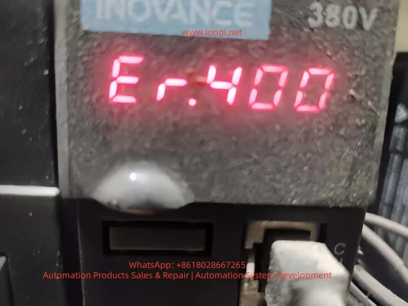
On the LED display panel of the IS620P series servo drive, the Er.400 code is displayed in red, usually accompanied by the system ceasing to respond. This code specifically indicates main circuit undervoltage, meaning the drive has detected that the voltage in the main circuit (including the input power supply, rectifier bridge, and bus capacitor) is below the preset safety threshold. According to the manual, the triggering conditions for the main circuit undervoltage fault include:
Voltage Detection Mechanism
The drive internally uses voltage sensors to continuously monitor the DC bus voltage between P⊕ and -. For a 380V-rated drive, the normal value is around 540V; for a 220V-rated drive, it is 310V. If the voltage remains below the threshold (e.g., below 420V or lower for a 380V system, depending on parameter settings), the system will trigger the Er.400 alarm and cut off the output to protect the hardware.
Internal Code Correspondence
In the Inovance drive debugging platform software, by reading the H0B-34 parameter, the hexadecimal code of the fault can be obtained (for the IS620N series, conversion is required). Er.400 corresponds to a subclass of main circuit voltage abnormalities, distinguishing it from Er.410 (which may indicate overvoltage, with different code divisions in some versions of the manual).
Fault Level
This fault belongs to Level NO.1 (a severe fault). It will immediately disable the servo enable (S-ON) and be recorded in the fault history (H0B group parameters). The system cannot be restarted without resetting the fault.
Understanding the meaning of Er.400 helps distinguish it from other voltage-related faults, such as Er.410 (main circuit overvoltage) or Er.920 (brake resistor overload). The former is caused by excessive voltage due to regenerative energy issues, while the latter involves the braking circuit. The occurrence of Er.400 often indicates problems in the power supply chain rather than abnormalities on the load side.
Possible Causes Analysis of the Er.400 Fault
The main circuit undervoltage fault is not caused by a single factor but is a comprehensive manifestation of various issues. According to the Inovance IS620P series servo common fault handling manual, the causes of Er.400 can be classified into four categories: external power supply problems, parameter setting errors, hardware damage, and environmental interference. The following is a detailed analysis of each category:
1. External Power Input Problems
- Low or Fluctuating Input Voltage: The power supply voltage is lower than the drive’s specifications (e.g., below 342V RMS for a 380V system). Reasons include grid fluctuations, insufficient transformer capacity, or voltage drops in long-distance cables. The manual states that if the phase-to-phase voltage is below 100%, an undervoltage will be triggered.
- Power Supply Type Mismatch: The H01-30 parameter (power supply voltage type setting) is incorrect. For example, setting a 380V drive to 220V mode results in a mismatch of the voltage detection threshold.
- Momentary Power Outage or Voltage Sag: Unstable power at the production site, such as voltage dips caused by the starting of large equipment or the impact of lightning strikes. The HOB-26 parameter can record the voltage value at the moment of power outage.
- Power Supply Phase Sequence Error or Phase Loss: One phase is disconnected in the three-phase input, leading to an unbalanced rectifier output.
2. Parameter Setting and Software Configuration Errors
- Abnormal Voltage Threshold Parameters: Improper settings of the H02-27 (external brake resistor value) or H0A group protection parameters. If the threshold is set too high, the system may misjudge as undervoltage.
- Motor-Drive Mismatch: Mismatched motor parameters in the H00 group, causing the current demand to exceed the power supply capacity and indirectly leading to a voltage drop.
- Software Version Incompatibility: After an upgrade, the factory settings are not restored (H02-31), resulting in abnormal voltage monitoring logic.
3. Hardware Component Damage
- Aging or Damaged Bus Capacitors: The capacitance of electrolytic capacitors decays, making it impossible to maintain a stable voltage. The manual recommends checking the voltage between the P-C terminals.
- Rectifier Bridge Fault: Diode breakdown or short-circuit, preventing the effective conversion of input AC to DC.
- Internal Circuit Problems in the Drive: Faults in the power module or voltage sensors, common in high-temperature and high-humidity environments.
- Poor Cable Connections: Loose, oxidized, or damaged main circuit cables, leading to increased contact resistance and large voltage drops.
4. Environmental and Operational Factors
- Overload Operation: High load inertia or frequent start-stop operations result in high current peaks, and the power supply cannot keep up.
- Electromagnetic Interference: Strong electromagnetic fields at the site interfere with the voltage detection circuit.
- Temperature Effects: The ambient temperature exceeds the specifications (-10°C – +50°C), affecting capacitor performance.
These causes are interrelated. For example, power fluctuations may accelerate hardware aging. Statistics show that external power supply problems account for more than 60% of Er.400 faults, followed by parameter errors.
Diagnostic Steps for the Er.400 Fault
Diagnosing the Er.400 fault requires following a logical process from simple to complex to avoid盲目 (blindly) disassembling the equipment. Based on the manual’s troubleshooting process, the following are detailed steps:
Step 1: Preliminary Observation and Recording
- Check the Display Panel: Confirm that the code is Er.400 and record the accompanying phenomena (e.g., the motor does not rotate, and there is no output response).
- View the Fault History: Read the H0B group parameters through the panel or software, and record the fault times, bus voltage (H0B-40), and input voltage (HOB-26) of the last 10 faults.
- Safely Cut Off the Power: Disconnect the main power supply and wait for the capacitors to discharge (the CHARGE light goes out).
Step 2: Power Input Inspection
- Measure the Phase-to-Phase Voltage: Use a multimeter (AC range) to measure the voltage between the R, S, and T phases. For a 380V system, it should be between 342V and 484V; for a 220V system, it should be between 198V RMS and 264V RMS. If it is below the lower limit, check the grid or transformer.
- Check the Phase Sequence and Phase Loss: Use a phase sequence meter to confirm the ABC sequence and ensure there is no phase loss.
- Monitor Voltage Fluctuations: Use an oscilloscope to observe the input waveform and confirm that there are no voltage sags (< 1ms).
Step 3: Parameter Verification
- Enter the Parameter Mode: Press the MODE key and check the H01-30 (power supply type, which should be 1 for three-phase 380V).
- Verify the Threshold: Check the H0A-00 (undervoltage threshold). The default value for a 380V system is 400V. Adjust it if necessary.
- Restore Factory Settings: Set H02-31 = 1, restart the drive, and observe whether the fault disappears.
Step 4: Hardware Inspection
- Check the Cables: Disassemble and inspect the R/S/T/U/V/W terminals to ensure there is no looseness or corrosion. Measure the cable resistance, which should be less than 0.1Ω.
- Measure the Bus Voltage: Use the DC range of a multimeter to measure the voltage between P⊕ and -. It should be approximately 1.414 times the input RMS value. If it is low, check the rectifier bridge (use the diode range to test forward and reverse conduction).
- Test the Capacitors: Use a capacitance meter to measure the capacitance of the bus capacitors. The normal value should be greater than 90% of the design value. If it has decayed, replace the capacitors.
- Check the Sensors: Monitor the analog output (CN5) through software to confirm that the voltage readings are accurate.
Step 5: Environmental and Load Evaluation
- Check Temperature and Humidity: Ensure that the ambient environment meets the specifications and there is no dust accumulation.
- Load Test: Run the drive without a load and observe whether the alarm is triggered. If not, check for mechanical jamming or excessive inertia (use the H09 group inertia identification).
- Eliminate Interference: Add a noise filter (recommended specifications in the manual) and ground the PE terminal.
During the diagnostic process, record data such as voltage values and parameter changes before and after to facilitate subsequent analysis. If self-inspection is ineffective, contact Inovance technical support.
Solutions for the Er.400 Fault
Targeted solutions are provided for different causes to ensure safe operation:
1. Power-Related Solutions
- Stabilize the Input: Install a voltage regulator or uninterruptible power supply (UPS) with a capacity greater than 1.5 times the drive’s power. For grid fluctuations, add a reactor with 4% impedance.
- Correct the Phase Sequence: Reconnect the wires to ensure a balanced three-phase supply.
- Handle Voltage Sags: Set the H0A-01 (undervoltage delay time) to 50ms to avoid false alarms.
2. Parameter Optimization
- Adjust H01-30: Match it with the actual voltage type and restart the drive.
- Fine-tune the Threshold: If the on-site voltage is relatively low, reduce the H0A-00 threshold by 5% – 10%, but do not exceed the safety limit.
- Upgrade the Software: Download the latest firmware from the Inovance official website. After upgrading, restore the factory settings and reconfigure the drive.
3. Hardware Maintenance
- Replace the Capacitors: Select electrolytic capacitors with the same specifications (e.g., 450V voltage rating) and pay attention to the polarity.
- Replace the Rectifier Bridge: Use a module of the same model and test its conduction.
- Maintain the Cables: Replace damaged cables and ensure that the cross-sectional area meets the requirements in the manual (e.g., 2.5mm² for a 3.5kW drive).
- If the Drive is Damaged: Replace the entire drive. The cost is approximately 2,000 – 5,000 yuan, depending on the power rating.
4. Preventive Measures
- Regular Inspections: Measure the voltage monthly and check the capacitors quarterly.
- Add Protection: Install surge absorbers (Varistors) with specifications matching a 380V system.
- Match the Load: Ensure that the motor’s rated current is less than 80% of the drive’s capacity.
After solving the problem, reset the alarm (using the ALM-RST input or setting H0D-00 = 1) and conduct a trial run with monitoring.
Preventive Measures for the Er.400 Fault
Prevention is better than cure. The following are long-term strategies based on the manual:
Power System Design
- Select high-quality transformers with a capacity margin of 20%. Avoid sharing the power grid with high-power equipment.
Parameter Backup
- Regularly export the parameters (through CN3/CN4 communication) for easy restoration.
Environmental Control
- Install fans or air conditioners to keep the temperature below 40°C. Use dust covers.
Maintenance Plan
- Conduct professional inspections of capacitors and cables annually, and use thermal imagers to check for hot spots.
Training and Monitoring
- Train operators on fault codes and integrate programmable logic controllers (PLCs) to monitor voltage parameters.
Backup Plan
- Maintain a spare parts inventory, including cables and capacitors, to reduce downtime.
These measures can reduce the incidence of Er.400 faults to below 1%.
Actual Case Studies
Case 1: Er.400 in a Semiconductor Manufacturing Equipment
On a surface mount technology (SMT) machine, an IS620P-3R7E-4A0C001 drive frequently reported Er.400. Diagnosis revealed input voltage fluctuations (370V – 390V) due to a shared power grid. Solution: A dedicated voltage regulator was added, and the H0A-00 was adjusted to 380V. The operation became stable, and downtime was reduced by 80%.
Case 2: Parameter Error in a Machine Tool Application
A machine tool servo reported Er.400, but the voltage was normal. The H01-30 parameter was set to 220V mode (incorrect). After correction and restart, the drive operated normally. Lesson: Always restore factory settings after software upgrades.
Case 3: Hardware Damage Caused by the Environment
On a food processing line, high humidity led to capacitor decay. The measured capacitance was only 70% of the normal value. After replacement, the problem was solved. Prevention: A dehumidifier was added.
These cases are based on real-world scenarios and highlight the diagnostic logic.
Differences and Associations between Er.400 and Other Related Faults
Difference from Er.410 (Main Circuit Overvoltage)
Er.410 indicates overvoltage (> 760V), often due to regenerative energy. Er.400 indicates undervoltage, focusing on the input side.
Association with Er.920 (Brake Resistor Overload)
Overloading may indirectly cause voltage instability. Check the H02-27 parameter.
Difference from Er.234 (Runaway)
Er.234 indicates speed runaway, which is not a voltage-related problem.
Comprehensive Faults
If accompanied by Er.207 (current overflow), there may be both power supply and load problems.
Distinguishing these faults helps in precise troubleshooting.
Related Parameter Settings and Advanced Debugging
Core Parameters
- H0A-00 (undervoltage level)
- H0A-01 (detection time)
- H02-21 (minimum brake resistor value)
Debugging Tools
Use the Inovance drive debugging platform, connect to CN3, and monitor the voltage curve in real-time.
Advanced Functions
Enable the H09 group self-adjustment function to automatically optimize the voltage response.